|
|
|
Porsche, and the Porsche crest are registered trademarks of Dr. Ing. h.c. F. Porsche AG.
This site is not affiliated with Porsche in any way. Its only purpose is to provide an online forum for car enthusiasts. All other trademarks are property of their respective owners. |
|
|

  |

| jj83118 |
 Oct 5 2008, 09:32 PM Oct 5 2008, 09:32 PM
Post
#21
|
|
Newbie  Group: Members Posts: 33 Joined: 12-May 05 From: Colorado Springs, CO Member No.: 4,066 Region Association: None |
I welded the crimped ends back on with a MIG welder and I did not weld all the way to the end. You don't want to weaken the cable.
I don't think I would attempt to silver solder or braze the ends as you will be fighting capillary action as the solder wicks its way up the cable. I'll have to check header clearance once the engine is put back in my car (it's been out for quite some time now). If there is interference, I might be able to put an Adel clamp on the cable and attach it to the trailing arm. |
   |

 
|
| andys |
Oct 6 2008, 10:57 AM
Post
#22
|
|
Advanced Member Group: Members Posts: 2,165 Joined: 21-May 03 From: Valencia, CA Member No.: 721 Region Association: None |
QUOTE(PRS914-6 @ Oct 5 2008, 07:50 AM)  Another thought on your idea........I don't have an arm here to look at but is there enough room to cut the arm (notch it) and weld a tube in its place with a straight shot to the mechanism? Also, I'm not sure but I'll look the next time my car is on the rack but there might be header interference with the cable out away from the arm...it's very close on a 6. Might need a tight 90 deg there. You can draw a sketch of exactly what you want and send it to Terry cable and they will manufacture the cable perfectly as you like. Wes, Very nice write-up! For you bell crank types, Wes came up with a very clever solution which employs a compound bell crank that provides opposing actions. He claims it's a bit too complex but, I disagree and think it's a unique solution and it allows the use of the stock e-brake cables. Wes, can you post some photos of this? The one funamental problem with the 911 e-brake is getting a nice straight shot at the actuator. All the solutions place the cable at a slight angle; I don't know for sure how much of a real issue this is (perhaps none) but it "seems" less than ideal. Short of modifying the trailing arm, you're pretty much stuck with this as is. Wilhelm, do you have a close photo of that 928 brake shoe spreader? Seems like it would simplify things quite a bit. Andys |
|
|
|
| Richard Casto |
Oct 6 2008, 12:49 PM
Post
#23
|
|
Blue Sky Motorsports, LLC Group: Members Posts: 1,465 Joined: 2-August 05 From: Durham, NC Member No.: 4,523 Region Association: South East States |
Wes,
Thanks for showing how you did this. I am still trying to decide how I am going to do this on my end. Richard |
|
|
|
| Richard Casto |
Oct 6 2008, 12:55 PM
Post
#24
|
|
Blue Sky Motorsports, LLC Group: Members Posts: 1,465 Joined: 2-August 05 From: Durham, NC Member No.: 4,523 Region Association: South East States |
QUOTE(Wilhelm @ Oct 5 2008, 01:52 PM) The 928,944, 924 mechanism requires only a pull, not compression of the spreader, and thus may be more suitable for the bellcrank crowd. The 928 shoes are the same size as the 944 and 911 and instead of having rivets for the spreaders to push on, have notches for the mechanism to lever on much like the brake shoes of american cars. The spreader is part 20 in this pic. I like the idea of the bellcrank approach because I would prefer to not make custom cables and would like to do this with off the shelf parts as much as possible. But I don't like how this does not compress the 911 spreader as it is supposed to. But the 928/944/924 pull mechanism sounds really interesting. Has anyone tried this yet? Richard |
|
|
|
| Wes V |
Oct 6 2008, 01:12 PM
Post
#25
|
|
Member Group: Members Posts: 482 Joined: 11-October 07 From: Los angeles Member No.: 8,211 |
This is what AndyS is talking about when he comments on the "lever" design I did. He knew about it due to my sending him photos for discussion.
Prior to working up the method in my write-up, I did a couple designs that involved a lever action, which would still work the "push and pull" on the 911 spreaders. I guess it's worth posting. (sorry about the first photo not being focused very well) (Andy also voiced consern on the "cable method" being too close to the exhaust) (IMG:http://www.performanceforum.com/wesvann/914a/my-rear-brake/lever1.jpg) In order to figure out how it works you first off have to know that the allen head bolts are shoulder bolts and work as pivot points. Then you have to know that the green arrow points to a "floating" pivot point. It isn't attached to anything other that the arms and can move in space. The last thing is that the pivot point pointed to by the red arrow would be attached to the trailing arm. It's a "fixed" pivot point. There is a short section of stainless steel tube that pushed on one of the spreaders, while a 1/4" thread rod pulls on the other. Ya, it would work, but I just thought there had to be a less complex way to do it. That black tie-wrap is just holding it in place for the photo. The following photos are showing the linkage on the garage floor, just to make it more clear. (IMG:http://www.performanceforum.com/wesvann/914a/my-rear-brake/lever2.jpg) (IMG:http://www.performanceforum.com/wesvann/914a/my-rear-brake/lever3.jpg) And the following photo shows the two arms. (IMG:http://www.performanceforum.com/wesvann/914a/my-rear-brake/lever4.jpg) The one on the right fits inside the one on the left. Both arms have a "bearing plate" on the end. The one on the left is what the length of tube bears on and also has a hole that the threaded rod can pass through. The one on the right is what the nut on the threaded rod bears on. Discuss away!! Wes Vann |
|
|
|
| Richard Casto |
Oct 6 2008, 01:47 PM
Post
#26
|
|
Blue Sky Motorsports, LLC Group: Members Posts: 1,465 Joined: 2-August 05 From: Durham, NC Member No.: 4,523 Region Association: South East States |
Wes,
Thats pretty cool. Basically its just like the regular bellcrank solution, but that the pivot point for the bellcrank is not static. So the force on a normal bellcrank pivot would be against the arm (with pivot bolted or welded to the arm). But in this solution the bellcrank pivot is free to move, so that force is now applied to the other half of the spreader. In a way its much like a cable solution because the cable is free to move a bit as well. I like it, but it is more parts, more fabrication and more things to go wrong. After looking at your solution I tried to sketch out some other ways to do it, but they basically result in something that is a bellcrank with a floating pivot and so far I can't think of something that is simplier than what you have. One thing I haven't seen anyone try to re-engineer is the 911 spreaders. A drop in replacement for those parts that only requires you to pull would be interesting. I still wonder if the 924/944/928 spreader mentioned earlier will work or not. Richard |
|
|
|
| Wes V |
Oct 6 2008, 02:03 PM
Post
#27
|
|
Member Group: Members Posts: 482 Joined: 11-October 07 From: Los angeles Member No.: 8,211 |
Richard;
In light of the fact you can figure out how it works, you have got to be an Engineer!! It's kind of a mind trip because you have to thing about things floating in space and balancing forces. I really don't think that there is a better "balanced bell crank" solution due to the physical restraints. My first attempt was better, but wouldn't clear everything as I hoped. You really have to build one to see how it clears stuff. The 924 solution is interesting, but without having parts in front of you it's hard to say how possible it would be. Here are things that come to mind; You would have to swap the brake shoes and spreaders at a minimum. Will the shoes fit on the 911 backing plate? Are the shoes the same size. Or viewed another way, is the drum diameter the same? You would have to modify the 911 backing plate to clear the spreader. If it's possible to swap the complete assembly, the attachment bolt spacing would be wrong (larger bearings on latter cars). It may just be a matter of opening up the bolt holes. I REALLY wish that I had a friend at a Porsche junk yard! Wes |
|
|
|
| Richard Casto |
Oct 6 2008, 03:43 PM
Post
#28
|
|
Blue Sky Motorsports, LLC Group: Members Posts: 1,465 Joined: 2-August 05 From: Durham, NC Member No.: 4,523 Region Association: South East States |
I am an Electrical Engineer by training, but I still remember my first year basic engineering classes (free body diagrams, etc.) that all the engineers had to take. (IMG:style_emoticons/default/wink.gif)
You are right on all of your points regarding the 924 solution. Someone just needs to assemble the parts and see what can be done. If someone wants to send me the 924/944/928 parts, I will give it a try and report back! (IMG:style_emoticons/default/biggrin.gif) |
|
|
|
| Wes V |
Oct 6 2008, 05:15 PM
Post
#29
|
|
Member Group: Members Posts: 482 Joined: 11-October 07 From: Los angeles Member No.: 8,211 |
QUOTE(Richard Casto @ Oct 6 2008, 02:43 PM) If someone wants to send me the 924/944/928 parts, I will give it a try and report back! Dang, I was wishing the same thing. I sure wouldn't mind somebody letting me have a -6 so I can verify exhaust clearances to the "cable" set-up. Of course, I'd need the 915 trans to mount it in place. Wes |
|
|
|
| Wilhelm |
Oct 6 2008, 08:25 PM
Post
#30
|
|
Member Group: Members Posts: 408 Joined: 7-September 07 From: Hooterville, OR Member No.: 8,088 Region Association: None |
QUOTE(andys @ Oct 6 2008, 08:57 AM) QUOTE(PRS914-6 @ Oct 5 2008, 07:50 AM) Another thought on your idea........I don't have an arm here to look at but is there enough room to cut the arm (notch it) and weld a tube in its place with a straight shot to the mechanism? Also, I'm not sure but I'll look the next time my car is on the rack but there might be header interference with the cable out away from the arm...it's very close on a 6. Might need a tight 90 deg there. You can draw a sketch of exactly what you want and send it to Terry cable and they will manufacture the cable perfectly as you like. Wes, Very nice write-up! For you bell crank types, Wes came up with a very clever solution which employs a compound bell crank that provides opposing actions. He claims it's a bit too complex but, I disagree and think it's a unique solution and it allows the use of the stock e-brake cables. Wes, can you post some photos of this? The one funamental problem with the 911 e-brake is getting a nice straight shot at the actuator. All the solutions place the cable at a slight angle; I don't know for sure how much of a real issue this is (perhaps none) but it "seems" less than ideal. Short of modifying the trailing arm, you're pretty much stuck with this as is. Wilhelm, do you have a close photo of that 928 brake shoe spreader? Seems like it would simplify things quite a bit. Andys Here they are: All the parts seperated 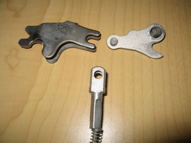 Cable attached 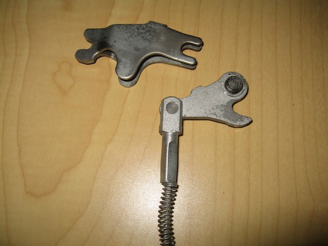 Hooked to spreader 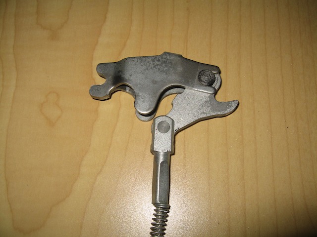 In the un-expanded mode 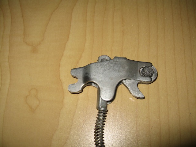 Again in the unexpanded mode attached to shoes 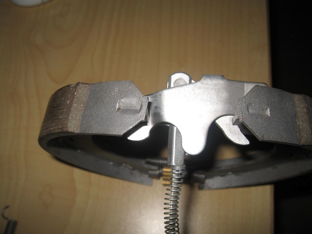 In the expanded mode attached to shoes (Note: the shoes are now farther apart) 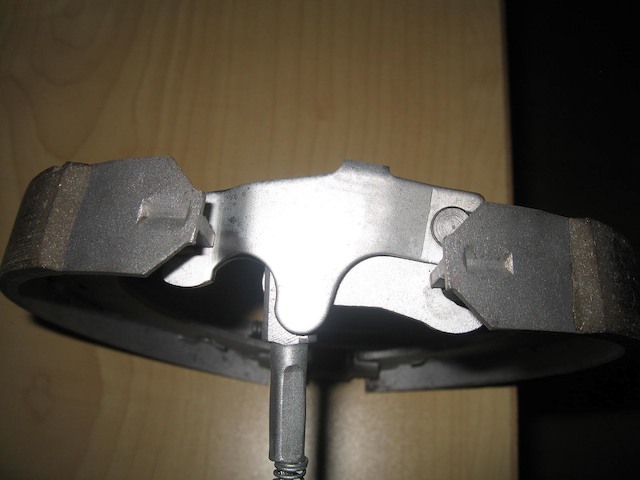 The end for the parking brake cables for this application can be found here: http://www.aircraftspruce.com/catalog/appages/ms20667.php This is what I'll be using with my trailing arms from another thread: http://www.914world.com/bbs2/index.php?showtopic=86910 |
|
|
|
| ClayPerrine |
Oct 6 2008, 09:53 PM
Post
#31
|
|
Life's been good to me so far..... Group: Admin Posts: 15,435 Joined: 11-September 03 From: Hurst, TX. Member No.: 1,143 Region Association: NineFourteenerVille |
I actually looked at the 924/944 solution. The mount for the cable is integral with the backing plate, and to use that backing plate would require way more modification than I am willing to do. Plus it puts the calipers behind the trailing arms, and they then hit the shock mount bolt.
The 944 shoes will fit the 911 backing plates. If someone made a mount to hold the expander and the end of the cable, it would work. But you are still left with custom cables. |
|
|
|
| Wilhelm |
Oct 6 2008, 10:37 PM
Post
#32
|
|
Member Group: Members Posts: 408 Joined: 7-September 07 From: Hooterville, OR Member No.: 8,088 Region Association: None |
QUOTE(ClayPerrine @ Oct 6 2008, 07:53 PM) I actually looked at the 924/944 solution. The mount for the cable is integral with the backing plate, and to use that backing plate would require way more modification than I am willing to do. Plus it puts the calipers behind the trailing arms, and they then hit the shock mount bolt. The 944 shoes will fit the 911 backing plates. If someone made a mount to hold the expander and the end of the cable, it would work. But you are still left with custom cables. Easy deal is to use the stock 914 cable terminating where it normally does. Pull the inner cable out and put in a bus cable (longer) . Now run this cable back to a small pulley (sheeve for you mariners) to change direction right in back of the pull point for the 944/928 spreader which should be a 6 oclock when using the 911 backing plate. Crimp one of these suckers on to the end of the cable http://www.aircraftspruce.com/catalog/appages/ms20667.php. The most challenging fab would be welding a bolt on for the pulley. I'll post a pict when I'm done. |
|
|
|
| ClayPerrine |
Oct 7 2008, 07:42 AM
Post
#33
|
|
Life's been good to me so far..... Group: Admin Posts: 15,435 Joined: 11-September 03 From: Hurst, TX. Member No.: 1,143 Region Association: NineFourteenerVille |
QUOTE(Wilhelm @ Oct 6 2008, 11:37 PM) QUOTE(ClayPerrine @ Oct 6 2008, 07:53 PM) I actually looked at the 924/944 solution. The mount for the cable is integral with the backing plate, and to use that backing plate would require way more modification than I am willing to do. Plus it puts the calipers behind the trailing arms, and they then hit the shock mount bolt. The 944 shoes will fit the 911 backing plates. If someone made a mount to hold the expander and the end of the cable, it would work. But you are still left with custom cables. Easy deal is to use the stock 914 cable terminating where it normally does. Pull the inner cable out and put in a bus cable (longer) . Now run this cable back to a small pulley (sheeve for you mariners) to change direction right in back of the pull point for the 944/928 spreader which should be a 6 oclock when using the 911 backing plate. Crimp one of these suckers on to the end of the cable http://www.aircraftspruce.com/catalog/appages/ms20667.php. The most challenging fab would be welding a bolt on for the pulley. I'll post a pict when I'm done. The spreader mechanism on a 944 mounts to the backing plate. The 944 backing plate will not fit a 914 trailing arm. Where are you going to mount the spreader? |
|
|
|
| Wes V |
Oct 7 2008, 11:03 AM
Post
#34
|
|
Member Group: Members Posts: 482 Joined: 11-October 07 From: Los angeles Member No.: 8,211 |
(I'm glad I started this sting)
Here's a bunch of thoughts and questions on the 944 spreader method (the "wilhelm" method). In the stock configuration, does the spreader assembly just float free, held in compression by the shoes? Looking back at the factory diagram posted by Wilhelm, what is item 23? What function does it serve? When Clay says that the backing plate supports the cable, to be specific, is he taking about the "dead-head" anchoring of the sheathing. I'm pretty sure this is what he is saying due to sheathing having to be fixed in order for this to work. This is significant due to the fact that it wouldn't be required if a bell-crank was used (as in some of the other methods. You couldn't use the VW bus cable due to it's end not being compatable. There just isn't any reason for it, other than being longer. I have to assume that there is somthing like the 40mm spacer at the spreader, as there is on the 911, welded to the trailing arm. Here is how I view it being done (if possible); Use the early 911 backing plate and cut out the minimum to allow the 944 spreader to fit. Mount the shoes and spreader. Fab up and weld in place the equivalent bracket as the 40mm one used in 911 installations. A hole would be needed for clearance for the "pull rod". Use a bell-crank as shown in prior posts. Connect the bell-crank to the spreader with a threaded rod and clevis. (NOT CABLE) Remove and relocate (weld) the bracket that holds the stock 914 cable, directing it toward the bell-crank. Attach the end of the stock 914 cable to the bell-crank using an "extension" arm as shown in prior posts, if required. If all this works, I really like the solution. The fabrication work isn't that complicated and it would provide the most clearance from things like the exhaust piping. I really wish that there was a 944 around here that I could take the rotors off and check it out, take measurements, and such. Wes |
|
|
|
| Wes V |
Oct 7 2008, 11:51 AM
Post
#35
|
|
Member Group: Members Posts: 482 Joined: 11-October 07 From: Los angeles Member No.: 8,211 |
I think it dawned on me why Clay said that the 944 spreader is "attached" to the backing plate.
I think it's that the backing plate prevents the spreader from being pulled outward by the cable. (IMG:http://www.performanceforum.com/wesvann/914a/my-rear-brake/944spreader.jpg) The green line would be the backing plate. The spreader would "wipe" across the backing plate a small amount. It may also help answer that that item 23 is. If this isn't the case, then function wise, it's doing pretty much what the "single spreader / pull only" method does. It would dig the brake shoes into the backing plate with the force applied by the pull cable. Fab'ing up this bearing plate in the correct location would be difficult (at least for me) and may be why Clay ruled it out. Wes |
|
|
|
| jcd914 |
Oct 7 2008, 12:56 PM
Post
#36
|
|
Advanced Member Group: Members Posts: 2,081 Joined: 7-February 08 From: Sacramento, CA Member No.: 8,684 Region Association: Northern California |
QUOTE(Wes V @ Oct 7 2008, 10:51 AM) I think it dawned on me why Clay said that the 944 spreader is "attached" to the backing plate. I think it's that the backing plate prevents the spreader from being pulled outward by the cable. I think you are correct here. Although I have not looked at the rear brakes of a 944 in a long time I think the spreader actually rests/is pulled against the backing plate nearer the ends of the spreader. The curved ends provide a pivot that is stable and would not move around much and have good leverage. The green lines here would be the backing plate. 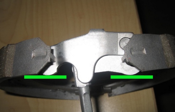 The opening in the backing plate for the cable would also have top be big enough to allow the nub on the spreader to clear. I do like the idea of using the 944 spreader with the bell crank method already used by some. Anyone know if real early 911 (66-68 with short wheelbase) rear parking brakes are any different than the rest? I have what I believe to be a set of 911 short rear trailing arms with brakes in my spare parts. Great thread Jim |
|
|
|
| ClayPerrine |
Oct 7 2008, 01:26 PM
Post
#37
|
|
Life's been good to me so far..... Group: Admin Posts: 15,435 Joined: 11-September 03 From: Hurst, TX. Member No.: 1,143 Region Association: NineFourteenerVille |
66-68 911 park brakes are the same as the later ones. The later ones just use a different center section on the backing plate for the different bearing.
|
|
|
|
| Wes V |
Oct 7 2008, 07:09 PM
Post
#38
|
|
Member Group: Members Posts: 482 Joined: 11-October 07 From: Los angeles Member No.: 8,211 |
I formally bow in humility to Clay Perrine! (IMG:style_emoticons/default/pray.gif)
I had the local Porsche dealer pull up the PET diagram that shows the 1981 924 backing plate and I can see that modifying the 911 backing plate to work in the same fashion would be difficult and I don't think it would be worth it!! The backing plate not only has the equivalent of the 40mm shoe support, but also the two bearing pads for the separator tabs (as shown by jcd914's diagram). All of that could be addressed, but the little details just keep adding up to the point where it's not worth it. (in my defence, I think it's always good to go in and "re-think" stuff that may be considered as fact) Wes Vann |
|
|
|
| craig downs |
Oct 7 2008, 11:55 PM
Post
#39
|
|
Senior Member Group: Members Posts: 768 Joined: 25-November 05 From: mira loma ca. Member No.: 5,189 Region Association: Southern California |
I've been working on this also for about two weeks. Knowing that other cars use this type of e-brake arrangement I went to Pick-a Part to look at some cars. Almost all European cars use this type of spreader.
The spreader didn't appear to be supported in the rear but relied on the notches in the shoes and spring tension from the shoes. The whole thing fit in a pocket in the backing plate that was part of the trailing arm. But one could and would be a good idea to put some support for it in the 40mm shoe anchor. |
|
|
|
| craig downs |
Oct 8 2008, 12:05 AM
Post
#40
|
|
Senior Member Group: Members Posts: 768 Joined: 25-November 05 From: mira loma ca. Member No.: 5,189 Region Association: Southern California |
Here a little what I've done
You have to remove a section of the backing plate to make room for the spreader 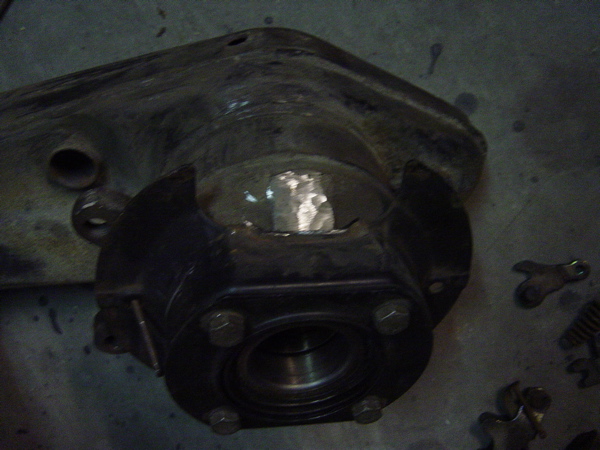 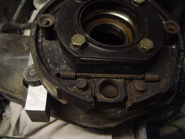 |
|
|
|
|
1 User(s) are reading this topic (1 Guests and 0 Anonymous Users)
0 Members:

|
Lo-Fi Version | Time is now: 4th May 2024 - 05:56 AM |
Invision Power Board
v9.1.4 © 2024 IPS, Inc.