|
|
|
Porsche, and the Porsche crest are registered trademarks of Dr. Ing. h.c. F. Porsche AG.
This site is not affiliated with Porsche in any way. Its only purpose is to provide an online forum for car enthusiasts. All other trademarks are property of their respective owners. |
|
|


| Wes V |
 Oct 4 2008, 07:07 PM Oct 4 2008, 07:07 PM
Post
#1
|
|
Member  Group: Members Posts: 482 Joined: 11-October 07 From: Los angeles Member No.: 8,211 |
I think I've come up with a totaly new way to hook up 911 parking brakes. It involves making up longer hybrid cables.
It's not complex, doesn't cost tons, and is about as straight forward as possible. It functions exactly as intended in the 911. Here is a teaser photo; (IMG:http://www.performanceforum.com/wesvann/914a/my-rear-brake/b-mrb1.jpg) Here is a link to my write-up on how I did it (it's a preliminary write-up). hybrid cables Wes (can somebody please find me the photo that I've seen on this site where somebody used a cable end block at the parking brake lever that had set screws) |
   |

 
|
  |
Replies(60 - 79)
| Eric_Shea |
Oct 9 2008, 06:49 PM
Post
#61
|
|
PMB Performance Group: Admin Posts: 19,275 Joined: 3-September 03 From: Salt Lake City, UT Member No.: 1,110 Region Association: Rocky Mountains |
I almost had it (IMG:style_emoticons/default/lol3.gif)
The "stop" prevents the shoes from being ripped off the entire assembly. That problem seems solved. |
|
|
|
| craig downs |
Oct 10 2008, 12:53 AM
Post
#62
|
|
Senior Member Group: Members Posts: 768 Joined: 25-November 05 From: mira loma ca. Member No.: 5,189 Region Association: Southern California |
Lots of good information this is a fun thread and totally different what Wes has started
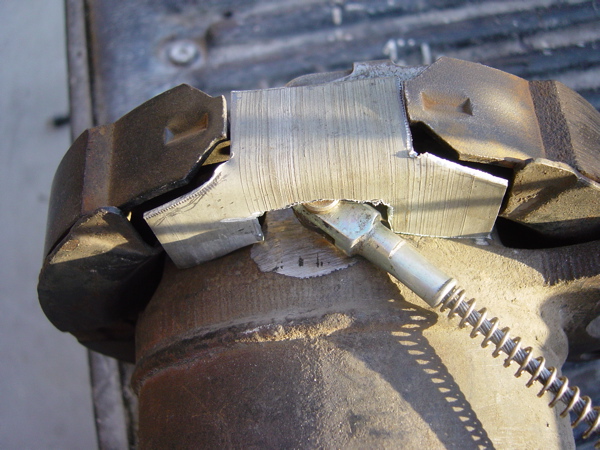
I hope you don't mine about your thread being hijacked. I was going to use the one from the BMW and use a bell crank to operate it until Richard Casto brought up about using the 924/944 spreader and hooking up direct. So today I explored this a I think its going to work as there will be no bell crank to make. Clay brought up an interesting point about the shoe stop. I checked to see if the shoes could be twisted back and forth and they could plus you can see a shiny area where the shoes would make contact with the stop. Here is what I found out today as I tried the 924/944 spreader 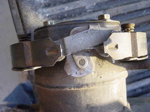 |
|
|
|
| craig downs |
Oct 10 2008, 01:00 AM
Post
#63
|
|
Senior Member Group: Members Posts: 768 Joined: 25-November 05 From: mira loma ca. Member No.: 5,189 Region Association: Southern California |
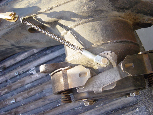
Checking cable line up. Going to cut and realign cable mount and make a rod extension to reach the spreader.
 |
|
|
|
| craig downs |
Oct 10 2008, 01:09 AM
Post
#64
|
|
Senior Member Group: Members Posts: 768 Joined: 25-November 05 From: mira loma ca. Member No.: 5,189 Region Association: Southern California |
In the relaxed position
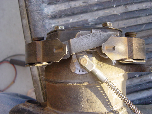 In the pulled position 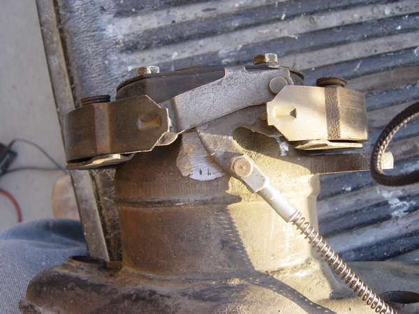 |
|
|
|
| craig downs |
Oct 10 2008, 01:17 AM
Post
#65
|
|
Senior Member Group: Members Posts: 768 Joined: 25-November 05 From: mira loma ca. Member No.: 5,189 Region Association: Southern California |
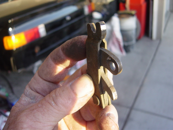
Mocking up a shoe stop I'll make them up this weekend. The stop will have to have support blocks welded on to reach the rear of the spreaders.
 |
|
|
|
| craig downs |
Oct 10 2008, 01:22 AM
Post
#66
|
|
Senior Member Group: Members Posts: 768 Joined: 25-November 05 From: mira loma ca. Member No.: 5,189 Region Association: Southern California |
This show why the spreaders need rear support as you see the shiny spots
 |
|
|
|
| Wes V |
Oct 10 2008, 09:02 AM
Post
#67
|
|
Member Group: Members Posts: 482 Joined: 11-October 07 From: Los angeles Member No.: 8,211 |
QUOTE(craig downs @ Oct 9 2008, 11:53 PM)  Lots of good information this is a fun thread and totally different what Wes has started I hope you don't mine about your thread being hijacked. I have NO problem with how this string has morphed!! (I originally just wanted to brag about finding that VW bus cable) There has been a lot of good information covered and ideas explored. I like the idea of it being in one area! I like what Craig is doing, however I think using a hard connection between the spreader and 914 cable would be easier to do than a cable. Think high strength threaded rod (from McMaster Carr) and clevis's. Am I correct that there is a "left" and a "right" version of the BMW spreader? It would seem that there would have to be in order to have the angle of pull match the side it's mounted on. Wes |
|
|
|
| Wes V |
Oct 10 2008, 09:23 AM
Post
#68
|
|
Member Group: Members Posts: 482 Joined: 11-October 07 From: Los angeles Member No.: 8,211 |
Craig;
Here is an idea for you to think about; Make up a clevis with a female m6x1.0 thread (I think that's the thread size, I'll check), then use that longer VW bus cable. It screws into the clevis and has a jam nut. By doing that, you would have a continuous cable (with about 18" exposed between the 914 sheathing bracket and the clevis). The bracket for the 914 cable sheathing would have to be re-located and pointed in the correct direction. Which you will have to do anyway. You would still have to make a cable end at the firewall area, but that's been covered. Wes Vann |
|
|
|
| Wes V |
Oct 10 2008, 09:50 AM
Post
#69
|
|
Member Group: Members Posts: 482 Joined: 11-October 07 From: Los angeles Member No.: 8,211 |
QUOTE(craig downs @ Oct 10 2008, 12:17 AM) The stop will have to have support blocks welded on to reach the rear of the spreaders. This comment has me confused!! As I read it, you are saying that there is a "stop" that limits how far to the side the spreader can move. (in addition to rubbing on the "backing plate") I can't see the need due to the fact that the shoe will only move outward a certain amount and that would limit the side to side movement. (as you pull on the cable, it would pull the spreader and shoe assembly off to that side and stop once that shoe is in contact with the drum. Then continuing to pull would spread the other shoe outward) It may have somthing to do with the fact that there will always be a certain amount of tension on the cable?? Maybe I'm just reading your comment wrong!!! If you could add an arrow to the photo showing the wear pattern on the spreader, it may make it clear. That brings up another subject! Are you planning on installing a "return" spring (as shown on that sub-cable)? I haven't seen anybody show consern about it, even in bell-crank versions. In most versions, everybody is counting on the shoe return spring (the one near the spreader) on pulling the cable back!!!!! In the original 911, there isn't an additional return spring, but that's a straight pull. What was there in the original BMW installation?? (wish I had a black E30 to look under!) Wes |
|
|
|
| Phoenix-MN |
Oct 10 2008, 09:57 AM
Post
#70
|
|
Senior Member Group: Members Posts: 927 Joined: 23-January 04 From: ST. Bonifacius,MN Member No.: 1,590 |
"Are you planning on installing a "return" spring (as shown on that sub-cable)? I haven't seen anybody show consern about it, even in bell-crank versions.
In most versions, everybody is counting on the shoe return spring (the one near the spreader) on pulling the cable back!!!!! " A spring like this? It pushes the spreader back when tension is released off the cable. 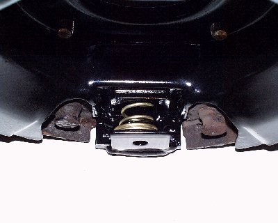 Paul |
|
|
|
| Richard Casto |
Oct 10 2008, 12:47 PM
Post
#71
|
|
Blue Sky Motorsports, LLC Group: Members Posts: 1,465 Joined: 2-August 05 From: Durham, NC Member No.: 4,523 Region Association: South East States |
QUOTE(Wes V @ Oct 10 2008, 11:50 AM) QUOTE(craig downs @ Oct 10 2008, 12:17 AM) The stop will have to have support blocks welded on to reach the rear of the spreaders. This comment has me confused!! Wes, you are a good sport for allowing the thread hijack. (IMG:style_emoticons/default/smile.gif) And Craig stop me if I am way off base here. So, I "think" that what Craig is saying when he says the "rear of the spreaders" is the part that would be next to the backing plate. And that in addition to pushing against the shoes, the spreaders also need to push against something along the other axis to prevent from putting an un-needed side load on the shoes. The image below is without a plate for the spreader to push against. The green arrow is the force from the cable. The red arrows is the force from the spreader on the shoes. So you see in addition to the force that pushes the shoes against the drum, you also have an un-needed side force. 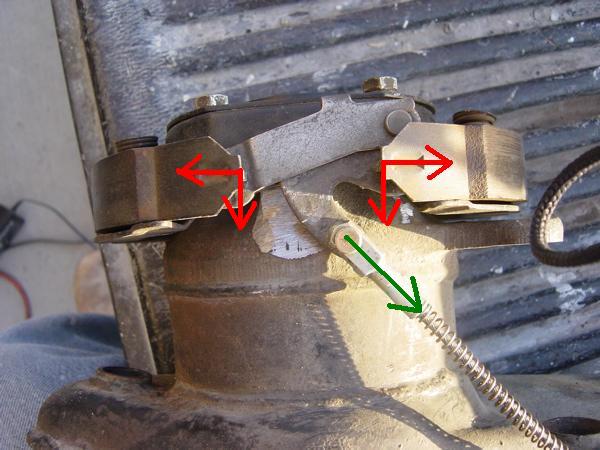 In the image below, the blue is a plate for the spreader to push against. The green arrow is the force from the cable. The red arrows is the force from the spreader on the shoes. The purple arrows is the force from the spreader on the blue plate. So here the only force on the shoes is the ones pushing them against the drum. 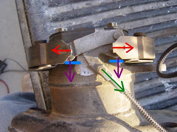 Also in the above photos you can see how the two pivot points on the spreader are offset away from what would be the backing plate. So if I understand Craig correctly, I think he is saying that in addition to just bending a flat section of metal 90 degree to create the “stopping block” that he may also need to weld in something extra (what I show in blue above) onto that to take into account that offset. In the image below, you can see the bent "stopping block" but with two extra sections welded on to account for the offset and meet up with the spreader. 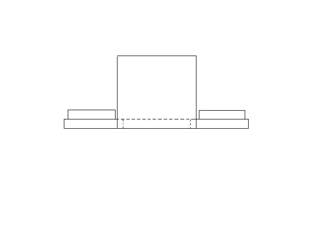 |
|
|
|
| Richard Casto |
Oct 10 2008, 12:50 PM
Post
#72
|
|
Blue Sky Motorsports, LLC Group: Members Posts: 1,465 Joined: 2-August 05 From: Durham, NC Member No.: 4,523 Region Association: South East States |
QUOTE(craig downs @ Oct 10 2008, 03:17 AM) Mocking up a shoe stop I'll make them up this weekend. The stop will have to have support blocks welded on to reach the rear of the spreaders. Looking at this image again and since I don't have the parts in hand, only Craig can answer this, but he may be sneaking his 90 degree bend section under the shoe a bit so that the two extra bits I just mentioned above may not be needed. That means the spreader might be able to rest directly on the part he has roughed out above. |
|
|
|
| Richard Casto |
Oct 10 2008, 01:01 PM
Post
#73
|
|
Blue Sky Motorsports, LLC Group: Members Posts: 1,465 Joined: 2-August 05 From: Durham, NC Member No.: 4,523 Region Association: South East States |
Continuing to think out loud here. I promise this is my last post for awhile. (IMG:style_emoticons/default/smile.gif)
Here is the backing plate for a 924 (image from PET)... 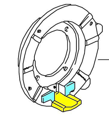 The yellow is what we are calling the "stopping block". On the 911, this is not part of the backing plate, but rather part of the arm. You can see how thick this casting is on the 924 vs the thin 911 stamping. The blue section that rises up higher than the surrounding area, is what I think the spreader pushes against. I think it rises up to account for the offset seen in the photos above. This might be what Craig is calling "support blocks" in his post above. Craig and others, what do you think?? |
|
|
|
| Wes V |
Oct 10 2008, 01:27 PM
Post
#74
|
|
Member Group: Members Posts: 482 Joined: 11-October 07 From: Los angeles Member No.: 8,211 |
Richard;
I think your "drawn" diagram is what Craig is talking about when he says he has to weld on something additional. (that's the only thing that makes sense) As you said, if the L shaped bracket is within the shoes, then it can be positioned such that added blocks wouldn't be required. Wes |
|
|
|
| smdubovsky |
Oct 10 2008, 04:05 PM
Post
#75
|
|
Member Group: Members Posts: 331 Joined: 27-September 04 From: Silver Spring, MD Member No.: 2,837 Region Association: MidAtlantic Region |
Heres a pic of an early steel 911 arm. The late aluminum arm is slightly thicker (didn't get a good photo on that one.) FWIW, the bracket is 39-40mm wide on both of them. I got to thinking - the tab is probably thick to account for shoe & rotor wear. The worst case limits are a new shoe on a new rotor (smallest ID) and worn shoes on worn rotors (largest ID). You don't want the lip of the shoe to slip over the block. That would wedge it in and lock the wheel in a big way.
I think there needs to be some sort of return spring. The little lever has a very high ratio. Cable drag could easily cause it to not fully release. 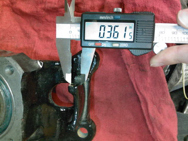 |
|
|
|
| craig downs |
Oct 10 2008, 07:04 PM
Post
#76
|
|
Senior Member Group: Members Posts: 768 Joined: 25-November 05 From: mira loma ca. Member No.: 5,189 Region Association: Southern California |
Richard figured it out what I was trying to explain about the rear supports. In his diagram the spreaders need back support where he has the blue lines.
As far as the spring goes I was planning on having a coil spring over the cable that goes from the cable housing to the top of the cable like the one I have pictured. All the cars I looked at they had a return spring around the cable. |
|
|
|
| Steve |
Jan 3 2009, 12:23 PM
Post
#77
|
|
914 Guru Group: Members Posts: 5,596 Joined: 14-June 03 From: Orange County, CA Member No.: 822 Region Association: Southern California |
I would love to do this to my car. Does anyone know of a shop or someone that can weld up the required brackets on my trailing arms in Southern Cal? I do not own a welder and haven't welded anything since high school 30 years ago.
Thanks!! |
|
|
|
| burton73 |
Jan 3 2009, 06:36 PM
Post
#78
|
|
burton73 Group: Members Posts: 3,530 Joined: 2-January 07 From: Los Angeles Member No.: 7,414 Region Association: Southern California |
Steve,
You are still going to need a set of rear p-Brakes. I paid $150. With the cables from Easy. Someone had a set with cables on the Pelican board for $175. Past that you can clean them up and paint them and them figure how to put them on. That is where I am. There are a few different ways to do it as shown by our members. Bob |
|
|
|
| charliew |
Jan 4 2009, 05:27 PM
Post
#79
|
|
Advanced Member Group: Members Posts: 2,363 Joined: 31-July 07 From: Crawford, TX. Member No.: 7,958 |
It looks to me that the aluminum arm style straight pull 911 spreader arm could be modified to be like the 944 spreader arm in a pinch and also if the leverage ratio needed to be changed, it could be done along with a different pull rod fastener if needed. ie a different size hole or etc.
Thats a great find on the angle spreader. |
|
|
|
| Steve |
Jan 4 2009, 07:57 PM
Post
#80
|
|
914 Guru Group: Members Posts: 5,596 Joined: 14-June 03 From: Orange County, CA Member No.: 822 Region Association: Southern California |
QUOTE(burton73 @ Jan 3 2009, 04:36 PM) Steve, You are still going to need a set of rear p-Brakes. I paid $150. With the cables from Easy. Someone had a set with cables on the Pelican board for $175. Past that you can clean them up and paint them and them figure how to put them on. That is where I am. There are a few different ways to do it as shown by our members. Bob Thanks Bob!! I pm'd the guy on Pelican but I haven't heard back from him. I will call some wrecking yards tomorrow and see what I can find. |
|
|
|
|
1 User(s) are reading this topic (1 Guests and 0 Anonymous Users)
0 Members:

|
Lo-Fi Version | Time is now: 23rd May 2024 - 09:48 PM |
Invision Power Board
v9.1.4 © 2024 IPS, Inc.