|
|
|
Porsche, and the Porsche crest are registered trademarks of Dr. Ing. h.c. F. Porsche AG.
This site is not affiliated with Porsche in any way. Its only purpose is to provide an online forum for car enthusiasts. All other trademarks are property of their respective owners. |
|
|

  |

| Eric_Shea |
 Feb 21 2009, 11:04 AM Feb 21 2009, 11:04 AM
Post
#41
|
|
PMB Performance  Group: Admin Posts: 19,275 Joined: 3-September 03 From: Salt Lake City, UT Member No.: 1,110 Region Association: Rocky Mountains |
|
   |

 
|
| JeffBowlsby |
Feb 21 2009, 11:30 AM
Post
#42
|
|
914 Wiring Harnesses Group: Members Posts: 8,510 Joined: 7-January 03 From: San Ramon CA Member No.: 104 Region Association: None |
Please post the specs of the items needed to fab this bearing puller?
Gud yob mon... (IMG:style_emoticons/default/biggrin.gif) QUOTE(MrKona @ Feb 20 2009, 10:30 PM)  And the result! Held the big bolt with a Vice Grip, turned the nut, and the bearing came out like buttah! Attached image(s) 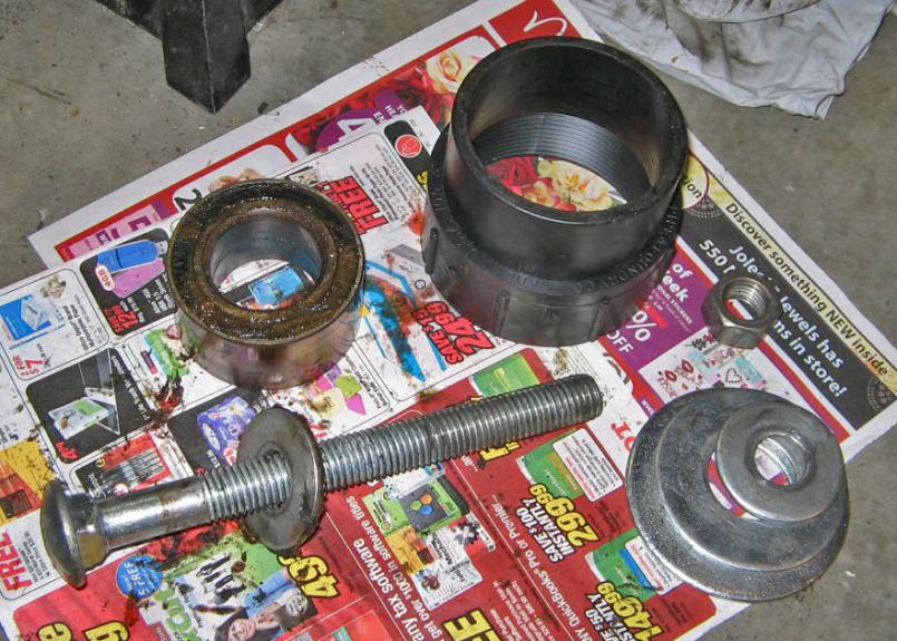
|
|
|
|
| MrKona |
Feb 21 2009, 12:29 PM
Post
#43
|
|
Senior Member Group: Members Posts: 597 Joined: 25-July 05 From: Santa Rosa, CA Member No.: 4,469 Region Association: None |
QUOTE(Eric_Shea @ Feb 21 2009, 09:04 AM) Yup, thanks guys. This morning I stuck a magnet onto it, you are right, it's all metal. Off to the metal cleaner these go for a bath. |
|
|
|
| MrKona |
Feb 21 2009, 12:36 PM
Post
#44
|
|
Senior Member Group: Members Posts: 597 Joined: 25-July 05 From: Santa Rosa, CA Member No.: 4,469 Region Association: None |
QUOTE(Jeff Bowlsby @ Feb 21 2009, 09:30 AM) Please post the specs of the items needed to fab this bearing puller? Gud yob mon... (IMG:style_emoticons/default/biggrin.gif) QUOTE(MrKona @ Feb 20 2009, 10:30 PM) And the result! Held the big bolt with a Vice Grip, turned the nut, and the bearing came out like buttah! Thanks Jeff. I used an 8" x 3/4 " bolt and appropriate nut. Of course, different threaded pieces could work. The important parts are: 1) Black piece, which is a "3" fitting cleanout adapter" from the plumbing section of the hardware store. The small end has a 3" ID and just shy of 3.5" OD. The large end (which rest on the trailing arm) has an ID of 3.5" and an OD of 4". 2) 2" diameter washer which mates with the bearing. 3) 3.5" large washer which rests on top of the black plumbing piece. I added a couple extra washers on top of the large washer as you can see from the pics. This really wasn't necessary. Only needed if the nut is too small for the hole in the large washer. Also, If I really wanted to get fancy and avoid holding the threads with a Vice grip, I could have added two additional nuts and cinched them tight to one another, then held one with a wrench to avoid gnarling up the threads. |
|
|
|
| MrKona |
Feb 21 2009, 12:39 PM
Post
#45
|
|
Senior Member Group: Members Posts: 597 Joined: 25-July 05 From: Santa Rosa, CA Member No.: 4,469 Region Association: None |
QUOTE(kconway @ Feb 21 2009, 07:07 AM) Did all of the bearing come out? Isn't there suppose to be a cover over the balls? Yup, it's there, it all came out. Hard to see with all the dirt and grease... |
|
|
|
| JeffBowlsby |
Feb 21 2009, 10:21 PM
Post
#46
|
|
914 Wiring Harnesses Group: Members Posts: 8,510 Joined: 7-January 03 From: San Ramon CA Member No.: 104 Region Association: None |
Thanks Bryan! That saves me some time...
QUOTE(MrKona @ Feb 21 2009, 10:36 AM) QUOTE(Jeff Bowlsby @ Feb 21 2009, 09:30 AM) Please post the specs of the items needed to fab this bearing puller? Gud yob mon... (IMG:style_emoticons/default/biggrin.gif) QUOTE(MrKona @ Feb 20 2009, 10:30 PM) And the result! Held the big bolt with a Vice Grip, turned the nut, and the bearing came out like buttah! Thanks Jeff. I used an 8" x 3/4 " bolt and appropriate nut. Of course, different threaded pieces could work. The important parts are: 1) Black piece, which is a "3" fitting cleanout adapter" from the plumbing section of the hardware store. The small end has a 3" ID and just shy of 3.5" OD. The large end (which rest on the trailing arm) has an ID of 3.5" and an OD of 4". 2) 2" diameter washer which mates with the bearing. 3) 3.5" large washer which rests on top of the black plumbing piece. I added a couple extra washers on top of the large washer as you can see from the pics. This really wasn't necessary. Only needed if the nut is too small for the hole in the large washer. Also, If I really wanted to get fancy and avoid holding the threads with a Vice grip, I could have added two additional nuts and cinched them tight to one another, then held one with a wrench to avoid gnarling up the threads. |
|
|
|
| Katmanken |
Feb 22 2009, 10:04 AM
Post
#47
|
|
You haven't seen me if anybody asks... Group: Members Posts: 4,738 Joined: 14-June 03 From: USA Member No.: 819 Region Association: Upper MidWest |
Looking at the splines, there are two different approaches used to make them.
The ones in your find are machined using a circular cutter that travels longitudinally along the lenght of the spline area. That type of machining would produce the characteristic "V" at the end of the groove (see red arrow). How would you do it in 1970's? Hans in the machine shop would attach to a mill and enables him to rotate the axle stub around the shaft axis in an increment of 360 degrees divided by the number of splines. Once the axle is held at the first groove positon positioned, Hans moves the bed into the axle to create a circular slot like a keyway, then Hans makes the bed travel longitudinally to cut the slot. Then Hans cranks the axle stub away from the cutter, and moves the bed back to the start position. He then rotates the axle by one spline amount and resarts the process. Remember, the whole time he is cranking this thing back and forth by hand to make the splines..... Or, maybe a rotary indexing tooling. For the production splines, you produce the square end in the groove (see blue arrows). To do this, you might use a rotary approach where a really hard spline tool is made that resembles a gear is both pressed into the axle (unhardened state) and and rotated around the axle shaft to produce the splines. Or, a linear broach could also make the square ends to the grooves. Prolly a few more processes but the point is, they may be a handmade very low volume part. Ken Attached image(s) 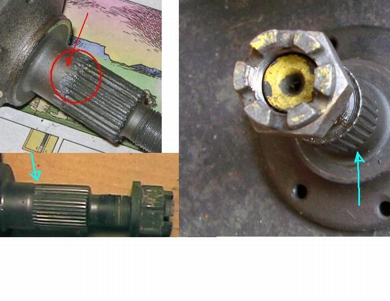
|
|
|
|
| MrKona |
Feb 22 2009, 12:23 PM
Post
#48
|
|
Senior Member Group: Members Posts: 597 Joined: 25-July 05 From: Santa Rosa, CA Member No.: 4,469 Region Association: None |
QUOTE(kwales @ Feb 22 2009, 08:04 AM) Looking at the splines, there are two different approaches used to make them. The ones in your find are machined using a circular cutter that travels longitudinally along the lenght of the spline area. That type of machining would produce the characteristic "V" at the end of the groove (see red arrow). How would you do it in 1970's? Hans in the machine shop would attach to a mill and enables him to rotate the axle stub around the shaft axis in an increment of 360 degrees divided by the number of splines. Once the axle is held at the first groove positon positioned, Hans moves the bed into the axle to create a circular slot like a keyway, then Hans makes the bed travel longitudinally to cut the slot. Then Hans cranks the axle stub away from the cutter, and moves the bed back to the start position. He then rotates the axle by one spline amount and resarts the process. Remember, the whole time he is cranking this thing back and forth by hand to make the splines..... Or, maybe a rotary indexing tooling. For the production splines, you produce the square end in the groove (see blue arrows). To do this, you might use a rotary approach where a really hard spline tool is made that resembles a gear is both pressed into the axle (unhardened state) and and rotated around the axle shaft to produce the splines. Or, a linear broach could also make the square ends to the grooves. Prolly a few more processes but the point is, they may be a handmade very low volume part. Ken Ken, Thanks - Very interesting information... - Bryan |
|
|
|
| MrKona |
Feb 22 2009, 09:25 PM
Post
#49
|
|
Senior Member Group: Members Posts: 597 Joined: 25-July 05 From: Santa Rosa, CA Member No.: 4,469 Region Association: None |
So what's the secret to removing the rubber bushings from the trailing arms? I heated up the metal around the bushing today, hoping to be able to pull it out in one piece. Yeah, right... Instead, it was bit, bit, by tiny bit of rubber. Is there a trick to it? (IMG:style_emoticons/default/idea.gif)
|
|
|
|
| Eric_Shea |
Feb 22 2009, 10:53 PM
Post
#50
|
|
PMB Performance Group: Admin Posts: 19,275 Joined: 3-September 03 From: Salt Lake City, UT Member No.: 1,110 Region Association: Rocky Mountains |
I use a simple press. It would probably pay for itself with this job. It's one of those things you can't go wrong with at HF for $99 bucks.
Step 1: Set the shelf to the proper height. Heat the shaft and press it through the fist bushing. You can see the bushing melt like butter as the hot shaft goes through it (settle down Slits). Step 2: Take a large screwdriver to the "inside" of the now exposed bushing and pry up. You should have to do this 3x before the bushing pops out. Step 3: Lower the shelf one notch, heat the shaft again and press it back through to it's original position. Step 4: Raise the shelf one notch, heat the shaft and press it the remaining way through until it pops out. Step 5: Repeat step 2. Hope that helps but... if you don't have a press or don't intend on getting one, maybe take these notes to a friend or shop that has one. Others will weigh in and tell you to burn them out and stink up your garage. (IMG:style_emoticons/default/biggrin.gif) |
|
|
|
| MrKona |
Feb 22 2009, 11:00 PM
Post
#51
|
|
Senior Member Group: Members Posts: 597 Joined: 25-July 05 From: Santa Rosa, CA Member No.: 4,469 Region Association: None |
QUOTE(Eric_Shea @ Feb 22 2009, 08:53 PM) I use a simple press. It would probably pay for itself with this job. It's one of those things you can't go wrong with at HF for $99 bucks. Step 1: Set the shelf to the proper height. Heat the shaft and press it through the fist bushing. You can see the bushing melt like butter as the hot shaft goes through it (settle down Slits). Step 2: Take a large screwdriver to the "inside" of the now exposed bushing and pry up. You should have to do this 3x before the bushing pops out. Step 3: Lower the shelf one notch, heat the shaft again and press it back through to it's original position. Step 4: Raise the shelf one notch, heat the shaft and press it the remaining way through until it pops out. Step 5: Repeat step 2. Hope that helps but... if you don't have a press or don't intend on getting one, maybe take these notes to a friend or shop that has one. Others will weigh in and tell you to burn them out and stink up your garage. (IMG:style_emoticons/default/biggrin.gif) Eric, thanks as always for your advice... This is not something I would have figured out on my own... |
|
|
|
| MrKona |
Mar 20 2009, 03:32 PM
Post
#52
|
|
Senior Member Group: Members Posts: 597 Joined: 25-July 05 From: Santa Rosa, CA Member No.: 4,469 Region Association: None |
Just got a pile of parts back from the metal cleaner today. I'll deliver these to the powder coater next week. The trailing arms in particular were covered with CV grease and caked dirt. All gone now.
I also had a rusty front cross bar and A-arms for the front done, as you can see. I'm pretty happy with how nicely they cleaned up. Attached thumbnail(s) 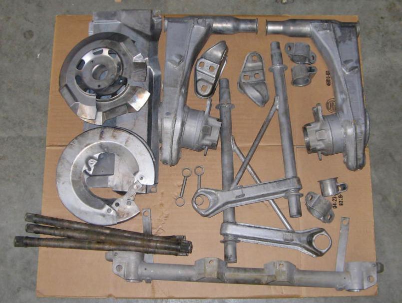
|
|
|
|
| MrKona |
Mar 20 2009, 03:33 PM
Post
#53
|
|
Senior Member Group: Members Posts: 597 Joined: 25-July 05 From: Santa Rosa, CA Member No.: 4,469 Region Association: None |
Another...
Attached thumbnail(s) 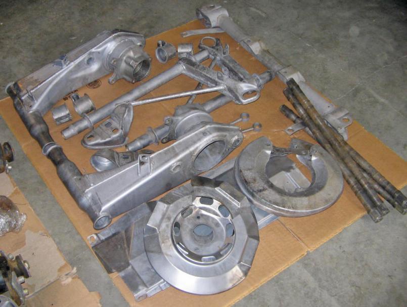
|
|
|
|
| MrKona |
Mar 20 2009, 03:34 PM
Post
#54
|
|
Senior Member Group: Members Posts: 597 Joined: 25-July 05 From: Santa Rosa, CA Member No.: 4,469 Region Association: None |
Eric - I'm going to send the clean stub axles and a couple other small pieces to you for zinc plating.
Attached image(s) 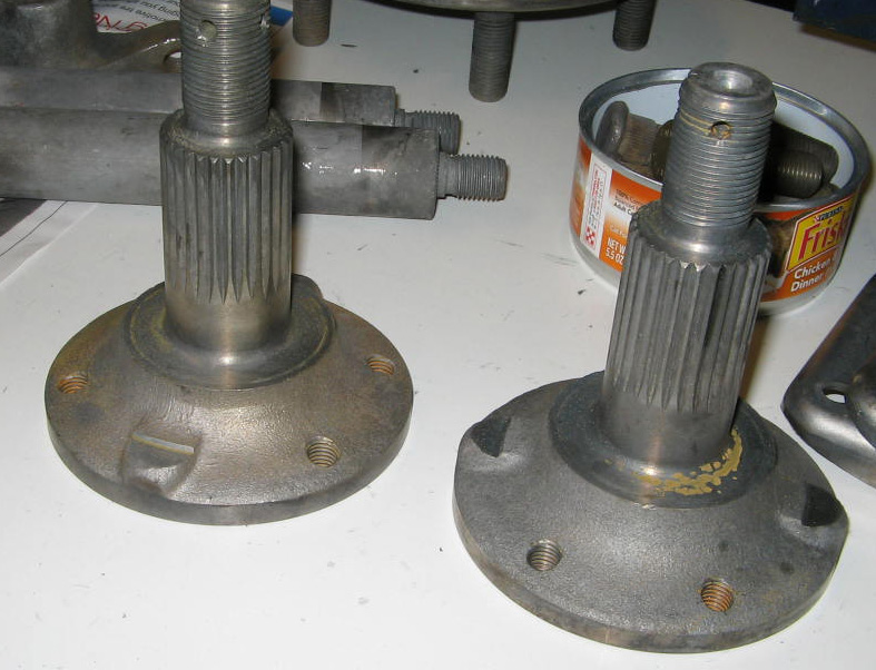
|
|
|
|
| MrKona |
Mar 20 2009, 03:39 PM
Post
#55
|
|
Senior Member Group: Members Posts: 597 Joined: 25-July 05 From: Santa Rosa, CA Member No.: 4,469 Region Association: None |
Also had the hubs cleaned. I'm going to blast off some surface rust that's beginning to form and paint the back side.
Attached thumbnail(s) 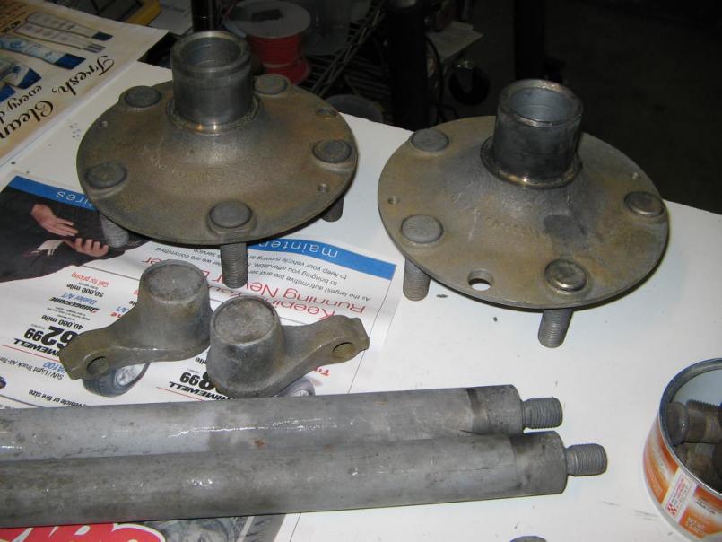
|
|
|
|
| MrKona |
Apr 3 2009, 08:16 PM
Post
#56
|
|
Senior Member Group: Members Posts: 597 Joined: 25-July 05 From: Santa Rosa, CA Member No.: 4,469 Region Association: None |
I have front and rear suspension projects going, so I'm going to merge them into this thread. The front suspension project is here.
I picked up powder coated parts today. As funds free up, I'll install new bearings, bushings, and hardware. My goal is to have my car back on the road this summer. It's been way too long since I've had this thing on the road. Unfortunately, as I readying parts for the powder coater, I discovered that one of the rear brake dust plates was cracked at the middle bolt hole. I then took both plates of my car - and both of them were cracked too! I'm going to hold off on coating until I can find one that is not cracked. Attached thumbnail(s) 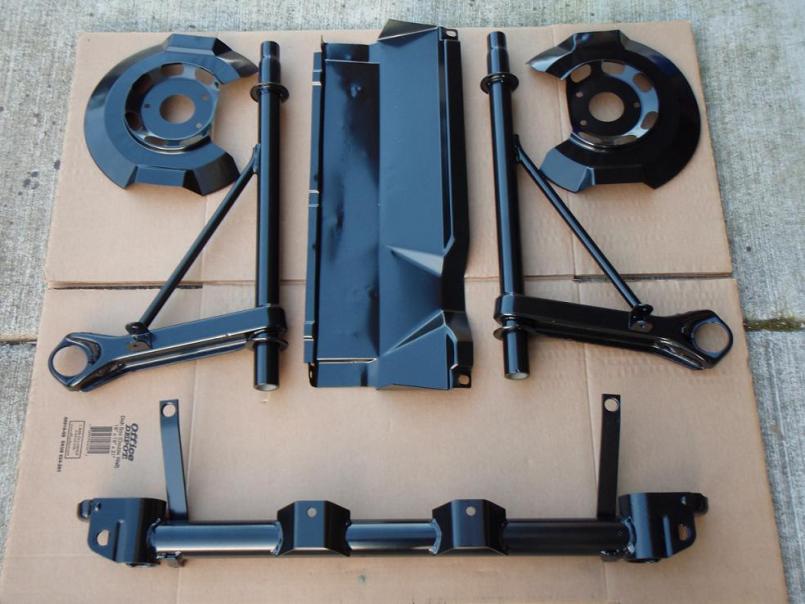 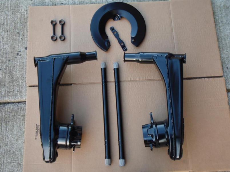 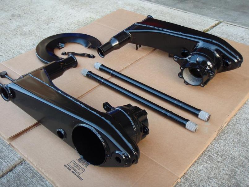
|
|
|
|
| charliew |
Apr 4 2009, 12:49 PM
Post
#57
|
|
Advanced Member Group: Members Posts: 2,363 Joined: 31-July 07 From: Crawford, TX. Member No.: 7,958 |
I guess this means you will use the solid rear rotors and their matching size calipers? How much did they charge to clean the parts? The only people I know that do that are motor shops and they won't do it unless you use them to build the motor.
|
|
|
|
| MrKona |
Apr 4 2009, 02:04 PM
Post
#58
|
|
Senior Member Group: Members Posts: 597 Joined: 25-July 05 From: Santa Rosa, CA Member No.: 4,469 Region Association: None |
QUOTE(charliew @ Apr 4 2009, 11:49 AM) I guess this means you will use the solid rear rotors and their matching size calipers? How much did they charge to clean the parts? The only people I know that do that are motor shops and they won't do it unless you use them to build the motor. Yep, I'll use 914-4 rear calipers and solid rotors. I already have a rebuilt pair. There is a place in Portland that does nothing but metal cleaning... from small parts to entire car bodies. American Metal Cleaning. All the stripped parts in the picture, plus four CV joints, hubs, stub axles, and strut caps was around $250. I have another box of rusty, grimy exhaust pipes, intake tubes, and plenum in a box to drop off on Monday. I'm going to try home painting the exhaust pipes with VHT paint to save $$$. The Powder coating was more expensive... to the point that I was up this morning thinking about it... (IMG:style_emoticons/default/barf.gif) |
|
|
|
| MrKona |
Apr 16 2009, 10:21 PM
Post
#59
|
|
Senior Member Group: Members Posts: 597 Joined: 25-July 05 From: Santa Rosa, CA Member No.: 4,469 Region Association: None |
I'm installing the rear bearings tonight. I started the bearing by tapping it in as straight as possible with a rubber mallet and then finished it with a press. On good advice from an expert here on the board, I pressed the arm down onto the bearing rather than pressing the bearing into the arm.
It was a little tricky keeping the bearing straight while in the press. I rested the arm and bearing on a press plate. Then I laid a 1/4" steel plate on the back side of the arm, across the larger opening, with a newspaper between the plate and arm so as not to scratch the powder coat. I then pressed a little, repositioned the arm slightly, pressed again, and so on until the bearing was almost all the way in, then I applied more pressure and the bearing seated nicely. Sorry no pictures, I was using both hands holding the arm in the press and I didn't want my wife to take pictures in case I really screwed something up. (IMG:style_emoticons/default/biggrin.gif) I had the bearing caps cleaned and zinc plated and I'm really happy with the results. Finished it off with new zinc plated bolts and wave washers, torqued to 18 ft/lbs. Attached thumbnail(s) 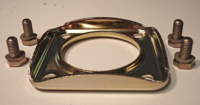 Attached image(s) 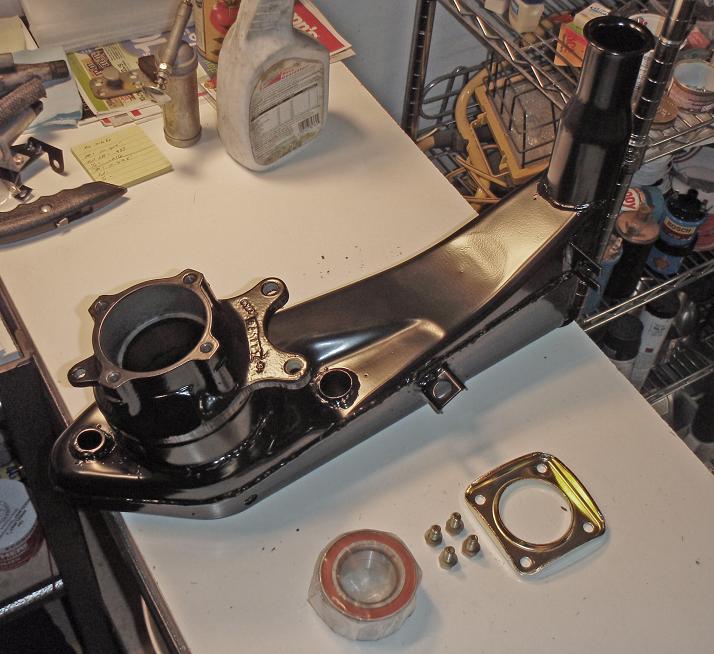 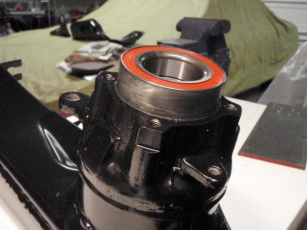 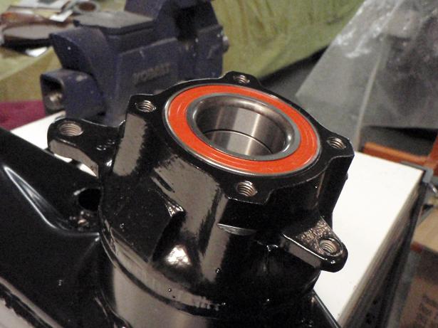 
|
|
|
|
| charliew |
Apr 18 2009, 09:47 AM
Post
#60
|
|
Advanced Member Group: Members Posts: 2,363 Joined: 31-July 07 From: Crawford, TX. Member No.: 7,958 |
If it's not too late. I have had real good luck with Eastwoods Stainless Steel paint for exhaust. I have used it on blasted bug headers and a k5 blazer exhaust and a case tractor exhaust and it has been on the k5 and case for several years and except for the bolts on the clamps it looks great. It's supposed to be cured at 400 but I used a torch and was careful not to burn it while I used a lazer temp gun to monitor the temps to cure it. The last time I just let the bug exhaust do the cooking. I always let the paint cure though before heating it up.
The only thing was the ss paint was really hard to clean out of the touchup gun and I ended up with some flake in a clear coat on a honda tank later on. I got it in a red pint can. I'm pretty sure it was from Eastwood but it might have been Restomotive or por 15 as most people say. |
|
|
|
|
1 User(s) are reading this topic (1 Guests and 0 Anonymous Users)
0 Members:

|
Lo-Fi Version | Time is now: 18th May 2024 - 11:01 PM |
Invision Power Board
v9.1.4 © 2024 IPS, Inc.