wiring my v8 and tell me what I have wrong or missing. my bad for never labeling the wires distributor is msd 8360 but you guys are smart and yes - I better connect that oil guage line or I will have a mess on my hands.
3d914
Sep 16 2013, 01:01 PM
IIRC the yellow wire goes to the positive side of the starter solenoid - what you labeled as ingition switch/pos toggle.
jimkelly
Sep 16 2013, 01:05 PM
thank you - I am editing my collage as we go.
jim
Spoke
Sep 16 2013, 02:13 PM
Page 5: Red wire from harness is 12V power to coil and distributor.
Page 6: Blue wire is from original voltage regulator. Unless that goes to a sender on the new alternator, you don't need this. You also don't need the original voltage regulator.
Page 6: The red wire to the battery doesn't look good at that terminal block. Also you need some sort of rubber cover for that connection. Touching that to any grounded point will result in fireworks as there is nothing to limit the current from the battery except the wire.
Page 6: Where does the blue wire go?
jimkelly
Sep 16 2013, 02:30 PM
spoke
I am pretty sure my ignition switch was partially bad - I had it partially bypassed and rigged with alternate switches but will replace the ignition switch asap.
and thank you for that other info!!!
the red wire to positive coil and distributor coming from harness, comes off this black wire with red (or maybe orange) stripe. makes sense.
1 = yellow, power to the starter 2 = blue, from alternator indicator light to D+ (red) on alternator harness 3 = grey/brown, from brakelight switch 4 = grey/brown, to brakelights 5 = green/red, oil-pressure sender to oil-pressure warning light 6 = not used 7 = black/purple, to tachometer, comes from pin #1 on coil 8 = black, from fuse #8, power for relays, goes to pin #15 on coil 9 = green/white, from heater blower switch to blower 10 = brown, to main ground connector 11 = green, to heater fan 12 = red, to battery 13 = black/red, to fuelpump 14 = red, to battery
jimkelly
Sep 16 2013, 07:31 PM
spoke
image 6 - the blue wire loops around and connects to one oft eh two recessed spades.
I am pretty sure my ignition switch was partially bad - I had it partially bypassed and rigged with alternate switches but will replace the ignition switch asap.
and thank you for that other info!!!
the red wire to positive coil and distributor coming from harness, comes off this black wire with red (or maybe orange) stripe. makes sense.
buy a renegade harness save tourself a lot of troublej
chads74
Sep 17 2013, 06:19 AM
QUOTE(jmmotorsports @ Sep 17 2013, 03:15 AM)
QUOTE(jimkelly @ Sep 16 2013, 01:30 PM)
spoke
I am pretty sure my ignition switch was partially bad - I had it partially bypassed and rigged with alternate switches but will replace the ignition switch asap.
and thank you for that other info!!!
the red wire to positive coil and distributor coming from harness, comes off this black wire with red (or maybe orange) stripe. makes sense.
buy a renegade harness save tourself a lot of troublej
I got the renegade harness and it was VERY easy to install. I ended up not using a couple of the wires, but it plugged right into the relay board and tells you exactly where the wires go. Took about an hour to run all the wires.
dwillouby
Sep 17 2013, 06:42 AM
I dont use the relay board. You need a switched 12 v and 12 v starter signal. Installed a 1 wire alt. I am using a MSD / Mallory system with Fast fuel injection. Very simple wiring setup David
Spoke
Sep 17 2013, 06:49 AM
QUOTE(jimkelly @ Sep 16 2013, 09:31 PM)
spoke
image 6 - the blue wire loops around and connects to one oft eh two recessed spades.
I wonder if my blue wire in image 4 went to my alternator?
this thread indicators that alt ind light is pin D+ on relay board which appears where my blue wire is connected in image 4.
That makes sense. That blue wire goes to the GEN light and to the open spade on your alternator.
You can remove the voltage regulator as that function is done inside of the new alternator.
jimkelly
Sep 17 2013, 07:03 AM
I was thinking that since it seems to be the only male spade remaining.
main image revised again.
thanks jim
jimkelly
Sep 17 2013, 08:01 AM
finally going to put my crimper and heat shrink to good use.
though I am not liking that the male double crimp connector has a different DOUBLE CRIMP portion than the female.
in fact, it seems to me, that the napa tool does not work on this male connector and despite mcmaster carr selling them as double crimp, I don't feel they are truly double crimp, as they don't really provide as decent of stress relief as the female's as they don't crimp well onto the wire insulator.
it seems to me, that my other crimp tool is better for these male's. see pics.
and some connector clean up.
preparing to start engine.
jimkelly
Sep 20 2013, 12:45 PM
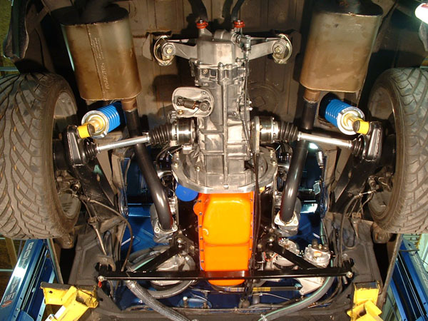
starter, shift linkage, gear oil, coolant fill neck, installed
Monday I swap out the early for late soft front passenger side brake line and add fluid and bleed.
for a whole this morning, I thought I had the firing sequence all buggered up, but after looking at it over and over again, i think it is ok.
waiting on ebay to deliver my CHROME dip stick and tube, I am sure engine is empty.
getting the correct grommets for front trunk is hell!!! one hose is 1.5 ID and the other is 1.7 ID, the bigger one is more of a challenge and the thicker the better as to have more rubber between hose and sheet metal, as mu old thinner grommets wore thru.
stock engine bay shift bar is 39.25" and renegade suggests adding 1.5" to this. the modified bar I have is 40" and should be fine but I will try to weld up a new straight one. as before I was using a custom engine bar, not renegade's..
76-914
Sep 20 2013, 02:19 PM
Jim, are you doing this and the Suby conversion or did the Suby get shit canned?
jimkelly
Sep 20 2013, 03:24 PM
I simply want to get the 1972 V8 running and functional - and then I want to focus, as resources allow, on my 1975, to be suby powered.
in all honesty, the V8 sucks gas and shifts like a 914.
I look forward to NOT SUCKING and SHIFTING modernly
now that I have a MIG up and running, I feel much more confident.
thanks jim
jimkelly
Sep 21 2013, 08:34 AM
just goofing around, since I already have a bar that fits.
I put a cut off wheel in my mitre box and cut some tailshift linkage and side shift linkage, both engine bay rods.
correction: cutting both bars just before the bends will give me a modded bar almost exactly 39.75" long tip to tip, 1" too short - i will ad 1", to get to 40.75". stock is 39.25".
note: it is odd that the side shift engine bay bar is neither totally straight, nor are the holes for the conical screws perfectly lined up. I will be ignoring this, since both are cocked ever so slightly.
also, I have to say, a flap disc kicks ass. grinds better than a grinding wheel in many cases. never expected that.
zambezi
Sep 21 2013, 12:31 PM
yes they grind better and produce less heat. Easier to control the amount you are grinding too so you don't grind away too much.
jimkelly
Sep 21 2013, 01:15 PM
engine bay shift rod done : )
40.75"
it is pretty darn straight, but I think the tang that goes into the console is tweaked - so I will tweak it back to straight a tiny bit.
and got my dip stick in the mail - made in korea of all places - and of course it won't seat fully, about 1/4 inch shy.
I found that after grinding an area, taking a DA sander to the area, makes it real nice.
ok - she is in - and she is pretty ; )
jimkelly
Sep 22 2013, 11:22 AM
some random pics
Mike Bellis
Sep 22 2013, 07:17 PM
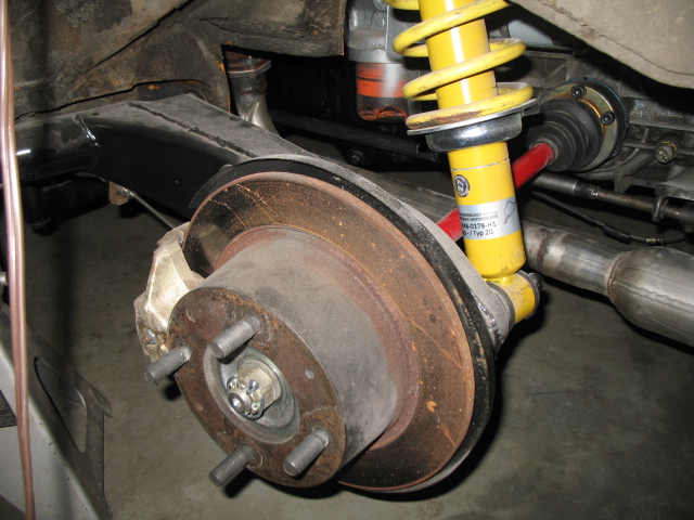
Your lower spring perch is upside down...
jimkelly
Sep 22 2013, 07:45 PM
thanks for that!!!
jim
jimkelly
Sep 23 2013, 07:41 AM
don't be an idiot like me.
anyway, one flipped and one left to do, waiting on bushing from bdstone : )
76-914
Sep 23 2013, 03:04 PM
Is that a "red" ground wire?
jimkelly
Sep 25 2013, 09:27 AM
from the relay board to the body? yes. I will change it.
side note: as for the water lines. the exactly correct grommets are a bitcvh to find, so I bought a few of these 2" ID grommets (ebay item # - 261171010853) on ebay cheap, and they will allow me to add some rubber around my hoses to give them even better protection. because my original, properly sized grommets wore thru, and I want to avoid any chance of my hoses getting damaged from contact with sheet metal.
pic shows my orig grommets used and how much sheet metal I need to grind away in order to install the 2" ID ones I just got. need to get a rasp bit.
hoses are 1.4" OD and 1.7" OD.
jimkelly
Sep 25 2013, 09:35 AM
also - before, I had the pos from alt running to pos on starter.
I guess it can be routed this way or directly to pos on battery?
Mike Bellis
Sep 25 2013, 09:01 PM
QUOTE(jimkelly @ Sep 25 2013, 08:35 AM)
also - before, I had the pos from alt running to pos on starter.
I guess it can be routed this way or directly to pos on battery?
It can be routed that way but... Crimp a ring on the red wire. Get rid of that mechanical lug; bad things will happen... Replace the "scotch lock" (bad things will happen) fitting on the yellow wire with a butt splice or solder & shrink tube. Finally replace the white wire with a wire the same gauge as the yellow one.
jimkelly
Sep 26 2013, 09:34 AM
mike - I will get those wires buttoned up - thanks.
and thanks to bdstone914 for some needed parts.
jimkelly
Sep 29 2013, 08:25 AM
guess i'll run the coolant lines today. the 2" ID gommets will be fine. I was able to wrap the 1.5" OD hose fully with old hose, but the 1.75" OD does not leave a big gap but I will stuff some rubber in there.
well, not sure I like the relatively short 90 degree bend of the large hose from under car to water pump, a curved tube of aluminum would be real nice here.
also, what could I put on the smaller hose that will reside only 4-5 inches from exhaust header?
BTW: sheet metal sheers cut thru coolant hose very nicely.
I found this 90 degree 1-1/4 OD bend on ebay and bought it.
bulitt
Sep 29 2013, 06:33 PM
I may have to get one of those 90's.
jimkelly
Sep 30 2013, 07:32 AM
since the only electrical connector I have, that has strain relief, is a female connector, I have been removing the insulators from my crappy connectors, crimping them and then heat shrinking them, to give these single crimp connections some weather protection and some amount of strain relief. like mcmark does, I always try to use narrow heat shrink and on top of that, next size up on all connections.
and today I organized my metric sockets - seems I have a 10mm shortage : ( I still need to organize my wrenches.
jimkelly
Oct 2 2013, 09:18 AM
rcvd the 90 degree tube today - looks good.
andys
Oct 2 2013, 09:26 AM
Much nicer with that aluminum 90!
Andys
speed metal army
Oct 2 2013, 10:05 PM
Hey Jim, weather pack electrical connectors are a cool solution that stays nice and clean. There is a few on my car. The spades are history!
jimkelly
Oct 7 2013, 11:41 AM
well, my car had a big gap, at top, between the drivers side door and the rear fender. I've been thinking of using a cut off wheel and cutting around the long, top and both sides, letting car settle into the gap, and welding the seam back up. but today I decided to add few washers to the door hinge as a less invasive approach. prior to today, door had to be slammed BRUTALLY HARD to close, but after washer treatment, 2 at top and 1 at bottom, and door closes nicely now. good enough for me.
next step is add coolant to cooling system, get a battery, and see if she starts.
I decided to lose the sheet metal screws and replace with bolts tacked to the floor (so hose install/removal is a one man job), a washer and a nylock nut. the sheet metal screws' pointy top protruding into thru the cabin floor was an issue.
socket on drill bit when you only want to go thru but not full bit depth.
JRust
Oct 7 2013, 08:11 PM
Yeah the aluminum 90% was a good move. I didn't like that bend with the gates hose either. I found a formed hose at the parts store to run from the firewall up. It was perfect from my buick setup. Looking good
jimkelly
Oct 9 2013, 01:12 PM
well two issues.
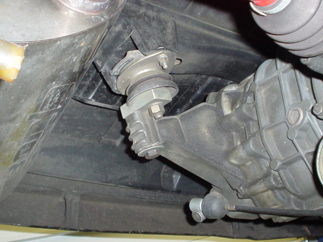
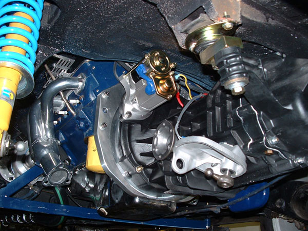
I need to either come up with a washer solution for the top bracket for engine mount, or I can just replace with rectangular steel and use longer main bolt. looking at the pic, I think I will get to perfect thick washers and grind the sides down so they will fit into the recess, might need 2 or three on each side.
second, do I need to move lower rear tranny mount washer to just above trans? right now it is just above the conversion/set back plate, above trans ear.
while making this video I realized I had some eng/trans movement.
The big washer with the groove goes on the bottom of the tranny ear. The groove to the inner side of the ear. The way you have it the tranny can slide right back off the bolt.
jimkelly
Oct 9 2013, 04:57 PM
I have been searching and have yet to find a pic or drawing that has this washer at bottom of trans. but I see it belongs at top of trans under normal circumstances. though I can see where putting it at bottom in this circumstance makes sense.
jimkelly
Oct 10 2013, 06:29 AM
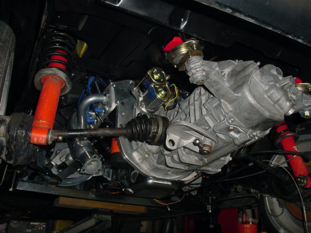
instead of this jumble of parts, I am thinking of installing a piece of 2" x 2" x 1/4" square steel tube which will require 3 holes and allow me to put a nylock nut on top of the bolt going thru the trans ear. reusing all hardware, just need the nylock nut.
bulitt
Oct 10 2013, 06:50 AM
I'm thinking you will break your trans ears off if you go with a solid tube. Heres some pics from Renegade site.
JRust
Oct 10 2013, 07:20 AM
QUOTE(jimkelly @ Oct 9 2013, 03:57 PM)
I have been searching and have yet to find a pic or drawing that has this washer at bottom of trans. but I see it belongs at top of trans under normal circumstances. though I can see where putting it at bottom in this circumstance makes sense.
Your right it is on top normally. I think it will still sit on top fine with renegade's block on top. Been a while since I messed with mine. I believe the lip it leaves will work. I may have used mine on the bottom flipped to accomplish the same thing. I guess it's worth trying both. Give Steve at Renegade a call
jimkelly
Oct 10 2013, 07:34 AM
for engine mounts, found washers that fit perfectly at ACE : )
and I agree about concerns of breaking off trans ear. certainly would have to make sure to loosen trans mount bolts BEFORE engine mount bolts, before tilting eng/trans assy at all. though I may just leave it as it is? maybe I just need a robust lock washer on the bolt going up thru the trans ear and into the renegade block as it appears some have done.
still getting some eng/trans shifting when shifting thru gears? and I do see my rear most trans bushing is shot.
That's how I eventually want to connect mine from the muffler exits back.
jimkelly
Oct 10 2013, 09:51 AM
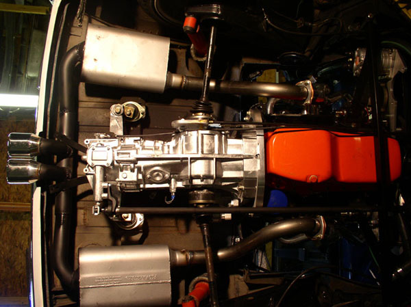
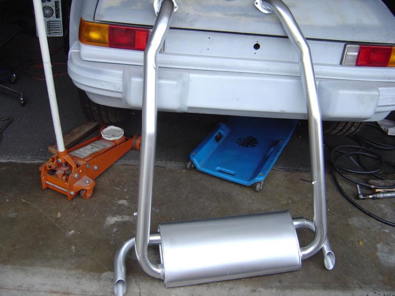
good point. behind trans is where the most space available for a cross over, I agree it is a good design and over axles is nice too, all tucked up.
shorter mufflers are the key and my hugger headers are NOT a good starting point.
but skline had a nice clean set up too. a 2 in 2 out muffler.
mittelmotor
Oct 10 2013, 01:22 PM
I like the 2-in/2-out approach as well. Keeps the sound level reasonable. Note hidden dump pipe on far side for stealth (relative term here for V-8 conversions!).
jimkelly
Oct 10 2013, 01:41 PM
well, finally got a battery today. hooked it up, and tested the starter. engine cranked over nicely (starter seems to be fully engage flywheel teeth - whew) and fuel pump ran. maybe tomorrow i'll stick the gas line into a gas can and fill the cooling system, and see if she starts. hopefully the timing is not too far off.
jimkelly
Oct 11 2013, 07:24 AM
hooked my fuel to gas but she backfires and pops. I am sure I have my spark plug wires wrong.
is it safe to say that if the notch on the front pully is directly up, then where the rotor points is #1 ?? engine is a 307. #3932373
she sputtering and back firing but not starting
or is this round mark at top of flywheel the tdc mark, indicating #1?
the pulley mark when at top is not when the flywheel mark is at top and vice versa. though it think the flywheel also has a straight line mark on it too? and I think it need to be visable thru bottom of trans view port?
wndsrfr
Oct 11 2013, 07:53 AM
QUOTE(jimkelly @ Oct 11 2013, 05:24 AM)
hooked my fuel to gas but she backfires and pops. I am sure I have my spark plug wires wrong.
is it safe to say that if the notch on the front pully is directly up, then where the rotor points is #1 ?? engine is a 307. #3932373
Not safe to say since you may have some mixed components such as timing cover vs. harmonic balancer. Here's a good thread to help you noodle it out:
Basically, get your firing order nailed first, Then be sure you're on TDC #1 cylinder using a long phillips screwdriver through the spark plug hole & noting valves closed on that cylinder. Note if the balancer timing mark aligns with the indicator on the timing cover. You can then stab the dizzy to align #1 plug wire with rotor or just move wire#1 to align with whatever you have....your choice there. Then arrange the other wires in correct firing order--(note dizzy rotation direction!). Then crank & twist dizzy by hand to fire her up. After that works, figure out where the timing mark indicator needs to be or make a new mark on the harmonic balancer pulley...
Others may have a simpler procedure or point out what I've left out....
jimkelly
Oct 11 2013, 08:22 AM
firing order seems to be 18436572 but finding tdc is gonna be my challenge it seems guess I got to pull a valve cover off first,and all spark plugs thanks
This is a "lo-fi" version of our main content. To view the full version with more information, formatting and images, please click here.