Want want want want want.
Seriously. I want this.
Zach
Full Version: Replacement Relay Socket Panel
QUOTE(Spoke @ Aug 16 2017, 05:48 AM) 
One question on the placement of SSR U6 for the low beam: Why is it turned around WRT to the other SSRs? With it's positioning, its exposed pad is not against the heatsink. Was this done for isolation? What is the theta-JC from junction to the EP versus junction to top of case?
I'm regretting the placement of U6 and it going to get flipped around for the next revision. I'll need to move a couple other components around to make that happen. I had it in that orientation originally to simplify routing. 7mm thick traces on both side are required to meet my current and temperature requirements, so routing was a bit of an issue. Thermal resistance junction to case is 0.3°C/W and junction to ambient is 33°C/W. The heatsink is approximately 28°C/W. I'm going to run a thermal test with a thermal camera with three of the relays carrying 12A, which should reflect worse case real world use. I'll incorporate anything learned from that test in the next revision.
QUOTE(Jeff Bowlsby @ Aug 16 2017, 07:32 AM)
Wondering...what is intended for a fuse panel cover? The stock cover indicates the functions of each fuse.
Thanks for answering my question. If its not critical to the connecting terminals, I think i will straighten it out to make injection molding much easier and cheaper. Is there a source for the stock cover? If reproductions are available, I would like to go with those to maintain some look of originality.
"3. The new fuseblocks do not have the bussed together lugs that the factory fuseblocks do, so makeshift additional terminal busses are needed or the circuitry is altered to accommodate, making the factory wiring schematic useless for troubleshooting."
This statement is not true. Engman had a flaw in his process of doing it, from what I understand, but did have it. Maybe he sold some without it? Mine have always been bussed just like factory and it is the most difficult part of manufacturing these, since they have to be fully disassembled and modified internally.
But irrelevant if this makes it into production. I am all for a better design, as I am not willing to put in the time to design a fuse box from scratch and the connection positioning is not optimal for the stock harness to bend around to reach. I keep it going since there is nothing better on the market.
Let me know when this makes it to retail sale and I'll push customers to it (or resell on my site if that is of interest to you).
QUOTE(Evan0 @ Aug 16 2017, 09:33 AM)
QUOTE(Spoke @ Aug 16 2017, 05:48 AM)
One question on the placement of SSR U6 for the low beam: Why is it turned around WRT to the other SSRs? With it's positioning, its exposed pad is not against the heatsink. Was this done for isolation? What is the theta-JC from junction to the EP versus junction to top of case?
I'm regretting the placement of U6 and it going to get flipped around for the next revision. I'll need to move a couple other components around to make that happen. I had it in that orientation originally to simplify routing. 7mm thick traces on both side are required to meet my current and temperature requirements, so routing was a bit of an issue. Thermal resistance junction to case is 0.3°C/W and junction to ambient is 33°C/W. The heatsink is approximately 28°C/W. I'm going to run a thermal test with a thermal camera with three of the relays carrying 12A, which should reflect worse case real world use. I'll incorporate anything learned from that test in the next revision.
QUOTE(Jeff Bowlsby @ Aug 16 2017, 07:32 AM)
Wondering...what is intended for a fuse panel cover? The stock cover indicates the functions of each fuse.
Thanks for answering my question. If its not critical to the connecting terminals, I think i will straighten it out to make injection molding much easier and cheaper. Is there a source for the stock cover? If reproductions are available, I would like to go with those to maintain some look of originality.
Personally I think the stock cover is not practical. Why not a sticker or silk screen over a cover One has to pull the fuse anyway to check it. .I.m with Jeff...KISS.
QUOTE(Evan0 @ Aug 16 2017, 12:33 PM)
I'm regretting the placement of U6 and it going to get flipped around for the next revision.
Very few products make it to production with Rev 1. I recently did a PCB for the people mover trains at Newark Airport where I reversed the coil leads for 6 relays.
 . Fixed it in Rev 2.
Update 8/26/2017
Been on vacation for the last couple weeks so not much progress. I did get around to doing a thermal test of the relay board.
Here's a picture of the test setup.
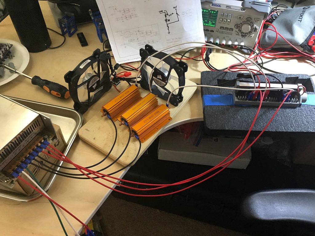
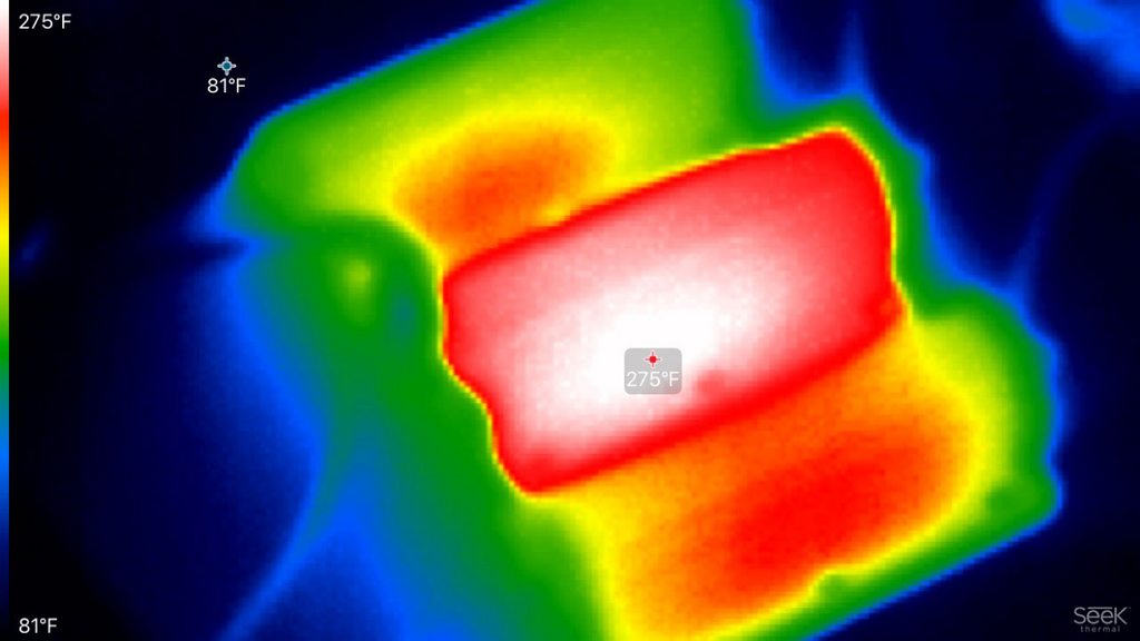
A 12V 600W power supply provides the juice to drive current through the solid state relays. Three 1Ω 200W resistors provide the load for the test. The fog, air fan, and low beam relays were chosen to as the test subjects since they are the high current draw items. The resistors actually measured about 1.2Ω so with 12V it should provide 10A through each of the relays. Left it running for about 20 minutes to reach steady state.
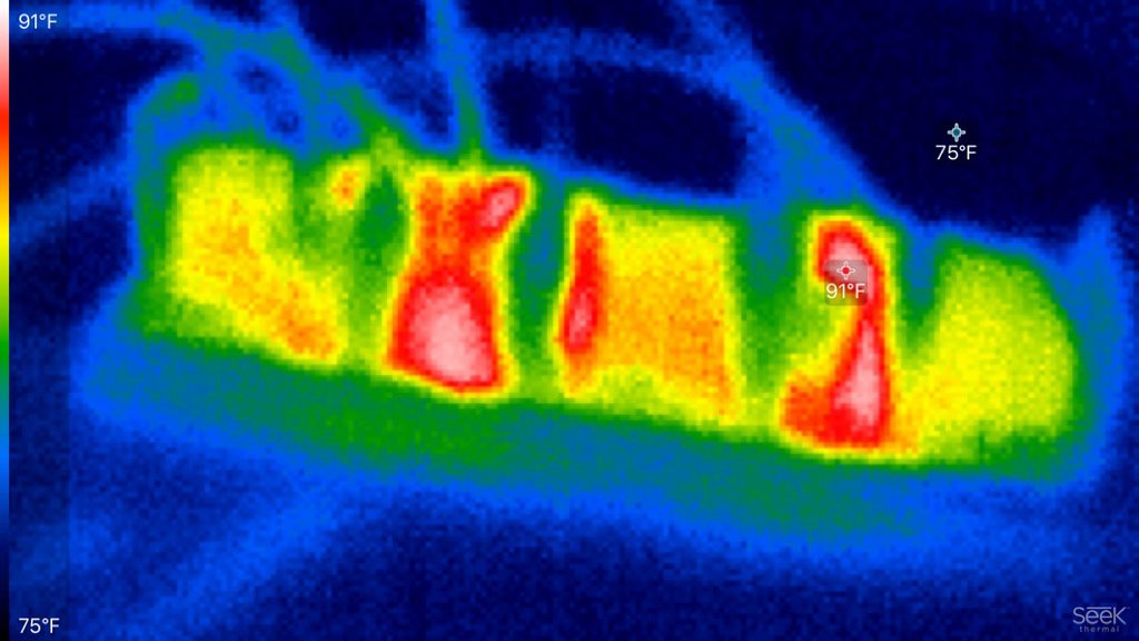
The max measured temperature was about 91°F, 15°F above ambient. Looks like the heatsink is doing its job correctly. The load resistors did get quite toasty during the test run.
With 30A passing through the PCB and the relays, there doesn't seem to by any issues. With these results I'll get to work with Rev B and figuring out how to mass produce these at a reasonable cost.
Been on vacation for the last couple weeks so not much progress. I did get around to doing a thermal test of the relay board.
Here's a picture of the test setup.
A 12V 600W power supply provides the juice to drive current through the solid state relays. Three 1Ω 200W resistors provide the load for the test. The fog, air fan, and low beam relays were chosen to as the test subjects since they are the high current draw items. The resistors actually measured about 1.2Ω so with 12V it should provide 10A through each of the relays. Left it running for about 20 minutes to reach steady state.
The max measured temperature was about 91°F, 15°F above ambient. Looks like the heatsink is doing its job correctly. The load resistors did get quite toasty during the test run.
With 30A passing through the PCB and the relays, there doesn't seem to by any issues. With these results I'll get to work with Rev B and figuring out how to mass produce these at a reasonable cost.
Any updates on this? I'm a few months away from tackling the electrical portions of my restoration and would love to commit to a fuse block solution.
This is a very cool project.. I would be interested.
I'm glad there are people in this world who are smart enough to know this stuff.
I have my own skill set, and I'm really good at Jeopardy, but thank you for making me feel like a complete nincompoop.
I have my own skill set, and I'm really good at Jeopardy, but thank you for making me feel like a complete nincompoop.
QUOTE(Larmo63 @ Nov 14 2017, 08:48 PM)
I'm glad there are people in this world who are smart enough to know this stuff.
I have my own skill set, and I'm really good at Jeopardy, but thank you for making me feel like a complete nincompoop.
I had a great feeling of accomplishment when I screwed the shift knob Zach had made for me, into the rennshifter lever. Righty tightly, lefty loosey.
Can't believe I miss this one too.
Quick question. Will these work with Spoke's LED turn-signals?
If so, this would definitely be something I'd be interested in too.
Quick question. Will these work with Spoke's LED turn-signals?
If so, this would definitely be something I'd be interested in too.
I can't say I totally followed everything that's been said on this thread, but it sounds like an awesome upgrade!
Would it be possible to add some extra connections for auxiliary items that weren't on the stock car? For example, my car has at least two extra connections (electric water pump and electric fuel pump, maybe more but I can't recall offhand), and they are just tied in via split spade connectors, which is horrible. Would love to have a proper spot on the fuse panel for them.
I'm thinking maybe 2 or 4 extra fused connections that people can use for whatever?
Does this even make sense? Keep in mind that I don't know anything about electronics...
Bump to encourage this project again. Getting closer to wiring the car, and with no one currently offering replacement fuseblocks I may need to grab an old one - really want something modern.
Very nice detail in the revisions along the way. I judge it to be an excellent upgrade and support the addition of multiple "unused" fuses in the offering. When will this setup be to market? I'm all in.

Amazing and passionate work! I’m in for at least one, as long as Jeff B. is ok with me connecting his harness to it 
...really great work!
...really great work!
I am in on this one - nice work.
Okay. Definitely in for one once released.
For the Subi crowd, 4 extra fused slots would be a great mod2. That would cover our electric fans, water pump, and fuel pump plus one.
Rob
For the Subi crowd, 4 extra fused slots would be a great mod2. That would cover our electric fans, water pump, and fuel pump plus one.
Rob
Put me on the list please..
Bumping an older thread. I still want this!
This is a "lo-fi" version of our main content. To view the full version with more information, formatting and images, please click here.