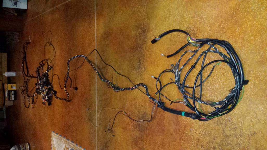
I just removed the wiring harness from my '75. I am not sure what the PO did or what happened but there are a lot of shorts with melted and exposed wiring. The seat wiring is melted into a large uniform mess.
I hate any form of lock out with seat belts. Can I remove the wiring and sensors or is there any reason I should restore the wiring under the seats and then make the modification to delete the lock out and fasten seat belt signals? I can't imagine a future owner thinking they would want to have the wiring available to connect a starter lock out to the seat belts.
Click to view attachment
Click to view attachment
Click to view attachment
Click to view attachment
Click to view attachment
Thanks,
DaveB
YIKES! 
Delete the whole harness. Buy a "new" harness. God only knows what else is going on in that thing.
I love being a contrarian  If you have more money than time, buy the RD harness. If you have more time than money, repair what you have. My harness didn't look any better than yours when I started. I couldn't find a good used one and wouldn't have been able to afford the RD harness even if they were available then. I fixed it myself and it looked like new when I was done.
And to answer your question, there are threads on bypassing the lockout. A quick search turned up this one: http://www.914world.com/bbs2/index.php?showtopic=51375
If you have more money than time, buy the RD harness. If you have more time than money, repair what you have. My harness didn't look any better than yours when I started. I couldn't find a good used one and wouldn't have been able to afford the RD harness even if they were available then. I fixed it myself and it looked like new when I was done.And to answer your question, there are threads on bypassing the lockout. A quick search turned up this one: http://www.914world.com/bbs2/index.php?showtopic=51375
QUOTE(windforfun @ Jun 1 2022, 03:14 PM) 
Delete the whole harness. Buy a "new" harness. God only knows what else is going on in that thing.
I could buy a harness but I'd like to learn how to repair this. I would have liked something that didn't make me say WTF every few minutes.
Oh it gets better.
I need to get a video on how to attach wires like this:
Click to view attachment
Here is the steering column washer/signal switches with the custom silver Porsche electrical wrap:
Click to view attachment
and looking down at the bearing for the steering wheel - it looks like the plastic disintegrated and explains why the steering wheel was flopping around.
Click to view attachment
Probably should have called this Project WTF. I should start a separate thread on the stuff we find in our cars from PO's. Doubt that would survive a few hours on Instagram.
DaveB
Lots of DAPO  going on there.
As Bbrock stated you can salvage it. I you have the money, I'd just find another good used harness and/or start with the new RD 914/6 harness.
New 914/6 from RD gets the nod if only because so many of these cars have old brittle and battle scarred wiring with only slightly less DAPO stuff done to them. Starting fresh would be wonderful.
If you do decide to repair, take a good look at what Tygaboy is doing for wiring as the role model. No matter what you do stay away from hardware store butt splices, low melting temp solder butt splices, electrical tape, and solder.
Proper crimps and tools can be had for less than $100.
going on there. As Bbrock stated you can salvage it. I you have the money, I'd just find another good used harness and/or start with the new RD 914/6 harness.
New 914/6 from RD gets the nod if only because so many of these cars have old brittle and battle scarred wiring with only slightly less DAPO stuff done to them. Starting fresh would be wonderful.
If you do decide to repair, take a good look at what Tygaboy is doing for wiring as the role model. No matter what you do stay away from hardware store butt splices, low melting temp solder butt splices, electrical tape, and solder.
Proper crimps and tools can be had for less than $100.
I removed pretty much out of my harness that wasn't being used including the seatbelt stuff under the seat. Cleans things up
Oh, what a mess! You have some skills if you can clean all that up!
Oh, what a mess! You have some skills if you can clean all that up!
I think your PO worked on my 914 cause it looks (the wiring that is) a lot like the wiring in my car. My suggestion would b "delete" not only the seat sensor wiring (which i did many many years ago to my first 914 with no issues). But i would also scrap the whole harness. Which is what i did to my current 914 wiring harness. I bought an aftermarket harness from summit racing. Most teeners will scoff at my suggestion cause I am ruining the "originality" of the vehicle. But iam both an iconoclast and my car is a true outlaw i.e. LS powered, Mendola transaxle, etc.
OP has a 1975 914/4 car. A 914/6 chassis harness is not interchangeable with any 914/4. Dash switches/guages relay board connections and more are not compatible. The only 914/4 harness apparently available is from Michael Sanger, but his site is not clear as to which 914/4 model year it is correct for. And I know of no one that has one.
https://www.msbordnetze.de/porsche-914.html
https://www.msbordnetze.de/porsche-914.html
So many of these cars get parted out. I would look for a new used harness.
QUOTE(JeffBowlsby @ Jun 1 2022, 07:23 PM)
OP has a 1975 914/4 car. A 914/6 chassis harness is not interchangeable with any 914/4. Dash switches/guages relay board connections and more are not compatible. The only 914/4 harness apparently available is from Michael Sanger, but his site is not clear as to which 914/4 model year it is correct for. And I know of no one that has one.
https://www.msbordnetze.de/porsche-914.html
Good catch. I didn't look to see what version RD sells. Just assumed they were makin all flavors by now.
I can say from experience that finding a good used harness for the right model year is like searching for a unicorn. It is a lot easier to say to buy a used one than actually buying one. But I did have luck with people donating chunks of harness to provide patches of color correct wire.
I have a couple used harnesses but I’m not sure if the later one is a 74 or 75. I’ll be at my daughter’s college graduation for the weekend but can pull it out for pics when I get back.
I found a nos harness for my 71 on German eBay for $850. I got lucky on that one.
I found a nos harness for my 71 on German eBay for $850. I got lucky on that one.
If you have the time redo the harness yourself. I did my brothers 74 2.0 now a 3.0 6 conversion. The main harness remained the same with a few added wires for other gauges to be used. Took me about 4 weeks at about 4 to 5 hours every other day. You can order the correct color wiring so give it a try. I also kept the wiring under the pass seat but jumped out the large yellow wire. IIRC if you cut that out the e brake light will not work properly . Jeff B may know as I asked him when I did it. His advise was to keep it.
Link to my brothers car :
http://www.914world.com/bbs2/index.php?sho...12849&st=80
Link to my brothers car :
http://www.914world.com/bbs2/index.php?sho...12849&st=80
We have made several /4 chassis harnesses as well. So they are available from us. They will cost the same as a /6 harness as they are equally labour intensive. Also there would be at least a 2 month wait. We have many orders to fill for wiring currently.
Cheers,
Pete
Cheers,
Pete
Looks like you'd like to understand the harness 7 fix it yourself.
here's the seatbelt interlock fix if you haven't seen this already (the heavy gauge yellow wires). Trace all those other wires back far enough to cut out any shorts.
Click to view attachment
here's the seatbelt interlock fix if you haven't seen this already (the heavy gauge yellow wires). Trace all those other wires back far enough to cut out any shorts.
Click to view attachment
First off, I must say I'm a big fan of Restoration Design's products - especially their in-house metal parts. I actually corresponded with RD on a 914/4 wiring harness during my restoration. They said they'd be happy to do it for me but I'd be charged by the hour with a minimum cost of something like $750. While the cost might work out to something close to the $2500 for the 914/6 harness (maybe more), I didn't feel like I should be the only one paying for their R&D. I simply don't understand why they don't create an early or late style full harness. IMO they'd sell a lot more then the /6s for sure!
I'd recommend cleaning the entire harness and removing any non-original wires or repairs. Next, I'd string it out on a sheet of plywood like the pros do it - using nails to hold it down. Take it one section at a time and simply make repairs and/or replace entire runs of wire at a time. Make sure you use the same gauge/color wire when possible.
I'd recommend cleaning the entire harness and removing any non-original wires or repairs. Next, I'd string it out on a sheet of plywood like the pros do it - using nails to hold it down. Take it one section at a time and simply make repairs and/or replace entire runs of wire at a time. Make sure you use the same gauge/color wire when possible.
There is no 'early' or 'late' chassis harness. There are at least 7 different 914/4 chassis harnesses and they are not interchangeable.
https://bowlsby.net/914/WiringHarnesses/doc...nessIDGuide.pdf
https://bowlsby.net/914/WiringHarnesses/doc...nessIDGuide.pdf
RD will sell you the wiring in factory colors/sizes - just email or call them. They're very helpful.
QUOTE(FlacaProductions @ Jun 2 2022, 10:40 AM)
RD will sell you the wiring in factory colors/sizes - just email or call them. They're very helpful.
That is great for some of my damaged or missing wires and bought the closest I could find and hand painted the stripes on them.
I appreciate all the input and suggestions.
I don't need a new complete harness. I'm adding a different ECU, so I have the engine area covered. Sounds like I can delete the seat wiring. So my focus is understanding what I have in the cockpit wiring and rebuilding it. Even though I've got a lot of issues with the wiring, it is complete. I have some time before I can start welding on the car, so I don't mind figuring out and repairing this harness. We've all been there before - we get a great deal on a car and then spend 5x more what a good driver would cost fixing it ourselves.
BTW - RD produces the best sheetmetal I've received plus great service.
Now I just need to mark where everything goes.
Click to view attachment
Click to view attachment
DaveB
Does anyone have a 1974 (about March production) car with the whole seatbelt thing still complete and functioning. I hate that the factory current flow diagrams do not match reality here. They only show the one relay when there are two. Plus several other wiring differences.
:wavy: I do. What are the specific differences?
Let me start with what goes to pin 31 and pin 85 on the logic relay. On a couple I have 85 black (311) + 85 black (133) + 30 black (133) go to junction terminal go to black & black/red, so the black & black/red do go to pin 30 on logic relay, but pin 85 on the logic relay is totally different in the flow diagram.
31 sometimes has 1 and sometimes 2 brown wires, totally uncertain where connections from 31 go to, flow diagram shows 2 wires with one going to interior light where there are 3 browns connecting, but some harnesses only have 2 brown on the light. So need to know just what wires go to the interior light.
31 sometimes has 1 and sometimes 2 brown wires, totally uncertain where connections from 31 go to, flow diagram shows 2 wires with one going to interior light where there are 3 browns connecting, but some harnesses only have 2 brown on the light. So need to know just what wires go to the interior light.
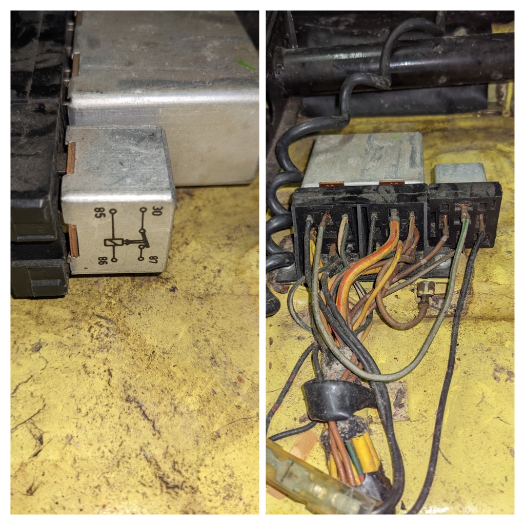
Van B posted this photo which shows that for his car there is a short brown wire from relay pin 31 that grounds to a spade under the relay base. Is this true for all years?
i'll see if i can get some time over weekend to get the drivers seat out (rhd  )
)
will photograph what is left there of mine.
did modify mine to incorporate a hidden kill switch 30 + years agp.
and of course killed off the interlock.
but it is still all there (more or less).
mine = late jan 74.
)will photograph what is left there of mine.
did modify mine to incorporate a hidden kill switch 30 + years agp.
and of course killed off the interlock.
but it is still all there (more or less).
mine = late jan 74.
A word of warning...
There is a small black wire in the seatbelt interlock harness that goes all the way back to the fuse box, and connects to the hot side of the ignition fuse. If it falls out of the plastic block, it will bounce against the floor board, and cause weird, intermittent ignition cutout. The car will randomly die doing things like driving over railroad tracks or on bumpy roads.
It is entirely possible that it would short out completely and burn the wiring harness.
I suggest you trace it back to the fuse box and cut the wire off at the spade connector.
Just so you know. I have been there, done that with Betty's 914. It took me months to find that out.
Clay
@JeffBowlsby
was there a formal campaign to fix the interlock system? Code?
Is there a list of items for the fix?
Just wonder because the Current flow diagram in the Technical manual does not show the second relay, and the wiring connections are so different. However, it seems to me that a recall could have meant adding the second relay, and rerouting some of the wires as well as bridging the yellow power wires. I see one wire coming from a sleeved bundle to the seatbelts that is brown with a .110 terminal on it and a second wire heading up to the interior light. This terminal looks like it should go to terminal 31, but a short ground wire to a tab below the sockets is fitted there, and there is no other place I can see where this loose terminal should go. It is in three or 4 harnesses I am looking at.
Dave
was there a formal campaign to fix the interlock system? Code?
Is there a list of items for the fix?
--> Not to my knowledge. Only a guess but someone a long time ago seems to have figured out that the logic box simply interrupts ignition power and that the two big yellow wires carried that current. Connect them together and voila! Bypassed.
Just wonder because the Current flow diagram in the Technical manual does not show the second relay, and the wiring connections are so different. However, it seems to me that a recall could have meant adding the second relay, and rerouting some of the wires as well as bridging the yellow power wires. I see one wire coming from a sleeved bundle to the seatbelts that is brown with a .110 terminal on it and a second wire heading up to the interior light. This terminal looks like it should go to terminal 31, but a short ground wire to a tab below the sockets is fitted there, and there is no other place I can see where this loose terminal should go. It is in three or 4 harnesses I am looking at.
Dave
--> Thats interesting, had no known that before. What are the two relays? Under the pass seat there is a seatbelt interlock logic box and the door open/fasten seatbelt buzzer. Neither are relays, but many call them that.
--> This interlock system also ran through the end of the 1976 cars, including all the 1974-76 model year cars.
--> I will need time to review this...have multiple harnesses in inventory and the factory schematic. May take me a couple weeks to respond.
QUOTE(JeffBowlsby @ Aug 29 2022, 05:00 PM)
was there a formal campaign to fix the interlock system? Code?
Is there a list of items for the fix?
--> Not to my knowledge. Only a guess but someone a long time ago seems to have figured out that the logic box simply interrupts ignition power and that the two big yellow wires carried that current. Connect them together and voila! Bypassed.
Just wonder because the Current flow diagram in the Technical manual does not show the second relay, and the wiring connections are so different. However, it seems to me that a recall could have meant adding the second relay, and rerouting some of the wires as well as bridging the yellow power wires. I see one wire coming from a sleeved bundle to the seatbelts that is brown with a .110 terminal on it and a second wire heading up to the interior light. This terminal looks like it should go to terminal 31, but a short ground wire to a tab below the sockets is fitted there, and there is no other place I can see where this loose terminal should go. It is in three or 4 harnesses I am looking at.
Dave
--> Thats interesting, had no known that before. What are the two relays? Under the pass seat there is a seatbelt interlock logic box and the door open/fasten seatbelt buzzer. Neither are relays, but many call them that.
--> This interlock system also ran through the end of the 1976 cars, including all the 1974-76 model year cars.
--> I will need time to review this...have multiple harnesses in inventory and the factory schematic. May take me a couple weeks to respond.
PS there is an early and late 1974 chassis harness. Early has cloth tape, late has vinyl tape and one has two wires to the MC switch, the other only has one (I forget which one is which at the moment)
Thanks Jeff. Just had another look at my LE, and noticed it has not had the 2 yellow wires bridged. Also, no short brown wire from pin 31 to the spade under the bracket, but the spade is there. The double brown wire that is loose on all the other harnesses ais loose on mine as well, but the pin 31 spot is open, so can go there. My interior light has just 2 brown wires, the others I have sport 3 wires.
The master cyl started with 2 pin switches, and went to just one, so the latter is later.
The 311-963-141-B, small cube is just a simple 15A power relay used in many applications and is available in many power levels to about 40 A or more under different part #'s. The buzzer must be integrated within the 133-919-431 (what I call the Logic relay) (In German it is marked as Logik-Relais, so who am I to argue). The buzzer, as used on the fuse panel is just a 2 pin device, so I think it is integrated, besides, the 311 relay has an obvious other purpose from the connections it has. I almost think the 311 relay was added and several wires rerouted, the 2 wire brown on 31 was replaced by the single brown to the spade and the black & black/red pair was pulled from 30 (133) and the triple black connected to it going to 85 (311) + 85 (133) + 30 (133) . This triple black is on my LE harness even though it uses a Marrette Twist-on connector.
Starbear says his early 74 1.8 also has several 1973 wiring characteristics; I will have to ask for specifics. I would really like to rewrite the current flow diagram to correctly reflect the actual cars.
The seatbelt connectors on my LE are mostly missing, so I want to be able to rebuild that section of it.
I think the factory current flow diagram for 1974 USA was correct at one time, but when and why it changed I do not know. Strange that the 1975 USA is the same as the 1974 in the logic relay connections as though nothing was formally changed. Then 1976 was simplified totally.
Dave, that photo above looks odd somehow. A Euro or Canadian amrket car or perhaps a one off customization? As far as I know the interlock system was only a USA legal requirement, and the single relay solutuion seems to be just a door buzzer indicator not an ignition lockout.
Not sure how specifically that it is different other than it does not have the double sized base and small cube (which I still think is a buzzer. It may be a power relay technically but it also buzzes) and the single logic box base connector is unlike any I have seen. I have over a dozen 74-76 chassis harnesses in my shop right now and none look like that. That base only has one screw and the logic box looks atypical to the USA cars. The euro cars did not have the seatbelt interlcok system as I understand, could these be euro market cars you have? The 74-76 USA cars do not have the round buzzer on the fuse panel like the 70-73 cars.
I assume you have seen my diagram of the wiring also attached. Thats all I have at the moment without further review.
Your photo there does not show if there is a spade below the socket, not if there is a wire attached to that spade. Your diagram has an error; 11 is missing in your list, but 10 on your list has the wires I see on 11, so the description for 10 is not correct.
My photo above was copied from another thread where the poster claimed that was in his 1976.
My photo above was copied from another thread where the poster claimed that was in his 1976.
This is a "lo-fi" version of our main content. To view the full version with more information, formatting and images, please click here.