|
|
|
Porsche, and the Porsche crest are registered trademarks of Dr. Ing. h.c. F. Porsche AG.
This site is not affiliated with Porsche in any way. Its only purpose is to provide an online forum for car enthusiasts. All other trademarks are property of their respective owners. |
|
|


| nathansnathan |
 Dec 3 2010, 05:22 PM Dec 3 2010, 05:22 PM
Post
#101
|
|
Senior Member  Group: Members Posts: 1,052 Joined: 31-May 10 From: Laguna Beach, CA Member No.: 11,782 Region Association: None |
(IMG:http://www.914world.com/bbs2/uploads_offsite/www.914club.com-11782-1291418830.1.jpg)
I changed the title of the thread, so it's incognito now. (IMG:style_emoticons/default/wink.gif) - Sort of to do with the midengined-ness, my username, and of course the 420 914 thing. (IMG:style_emoticons/default/smoke.gif) The car was very original, but quite trashed when I bought it. It's a 49 state car, purchased in Colorado judging by the sticker that was on the back opposite the badge, Bob Hagestad Dealerhip. I don't have a picture of that unfortunately... Both bumpers had 1975 UCLA parking permit stickers. It is an appearance group car, tan square weave, late enough to get 2 real tan basket weave seats. Original adriatic blue paint, no repaints. The snowplow early rear valence. It has the original red heater lever pull which I don't see very much. Everything was there without having been hacked/modified (besides the door panels). Unmodified but fairly trashed. 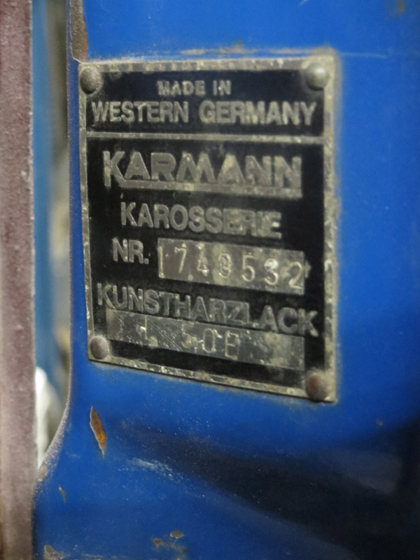 Chassis # 174932 -Meaning the chassis was built the 17th week of the year 1972 (I think it is the 17th week with a Monday the way they count it), the 4th day of that week, Thursday April 27th, 1972. -I thought it was 4/20 but I must concede it was probably a week later, the chassis production. (IMG:http://www.914world.com/bbs2/uploads/post-179-1307065668.jpg) It is odd, though, the dash doesn't match. 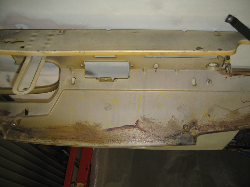 1729556 vs 1749532 which is on the Karmann plate and the trunk. It would be from just 2 days earlier, but then I was thinking, if it was from another car, it could theoretically be from a 73 or a 74 car, too. It seems like it is original, though, as peple always bodge everything and it was fairly unmolested, the wiring, and hardware of the dash. 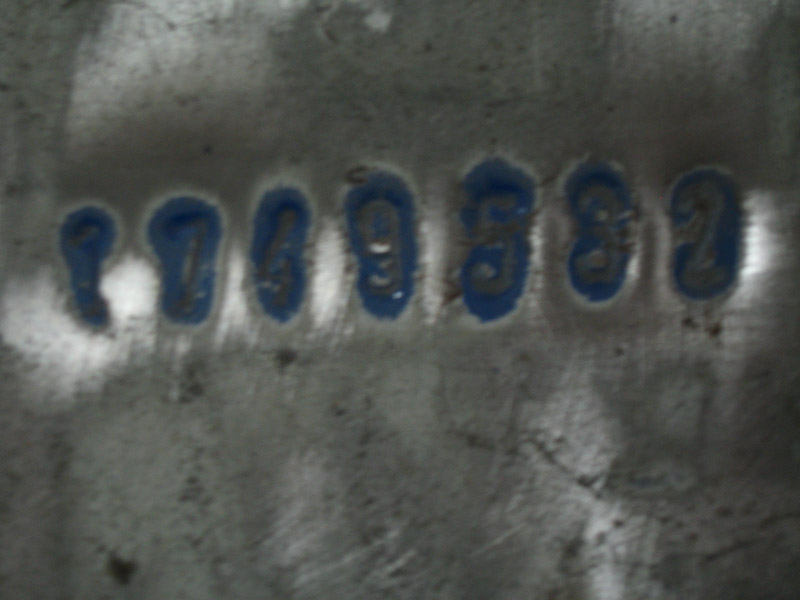 (IMG:http://www.914world.com/bbs2/uploads_offsite/www.914club.com-11782-1291418830.2.jpg) 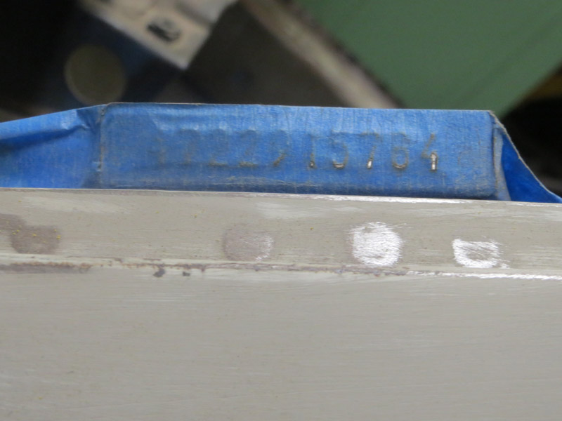 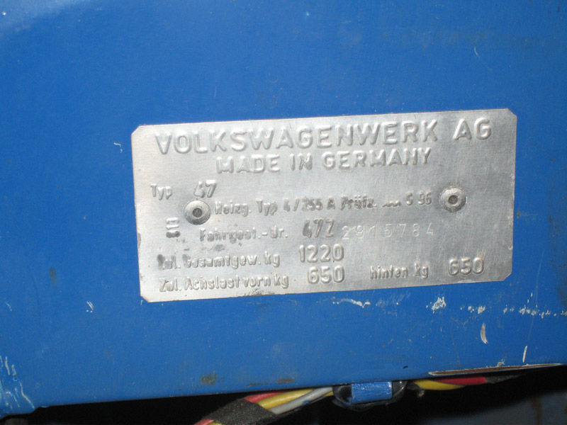 The engine number... (IMG:http://www.914world.com/bbs2/uploads_offsite/www.914club.com-11782-1296535790.12.jpg) |
   |

 
|
Posts in this topic
 nathansnathan Palindrome 914 Build Thread Dec 3 2010, 05:22 PM
 nathansnathan These are the first pics I saw, back in June on cr... Dec 3 2010, 05:27 PM nathansnathan I sort of wanted to get it running just to see wha... Dec 3 2010, 05:28 PM nathansnathan I've been stalling on updating the blog in hop... Dec 3 2010, 05:29 PM nathansnathan I woke up at 4:30 in the morning to go to the 914 ... Dec 3 2010, 05:35 PM nathansnathan So first things first, like many-a-914, put her up... Dec 3 2010, 05:37 PM nathansnathan Unbelievable how much undercoat was used at the fa... Dec 3 2010, 05:40 PM
 roadster fan
http://www.914world.com/bbs2/uploads_offsite/www... Dec 4 2010, 03:26 PM nathansnathan
[quote name='nathansnathan' post='1401717' date='... Dec 5 2010, 05:19 PM nathansnathan I've got one of these bad boys done so far. It... Dec 3 2010, 05:41 PM nathansnathan Ok, so I'm caught up to the blog over at 914cl... Dec 3 2010, 05:42 PM McMark Cool! B) Looking forward to more! Dec 3 2010, 05:48 PM SirAndy
Cool! B) Looking forward to more!
:ag... Dec 3 2010, 06:07 PM nathansnathan
[quote name='McMark' post='1401720' date='Dec 3 2... Dec 3 2010, 09:31 PM Mark Henry From the title I thought you were restoring a 914 ... Dec 3 2010, 06:53 PM palmer_md
From the title I thought you were restoring a 914... Dec 3 2010, 07:42 PM Mark Henry
From the title I thought you were restoring a 91... Dec 3 2010, 09:12 PM nathansnathan
From the title I thought you were restoring a 91... Dec 3 2010, 09:27 PM FourBlades Very nice work! You have done this before?
I... Dec 3 2010, 07:21 PM nathansnathan
Very nice work! You have done this before?
... Dec 3 2010, 09:28 PM SirAndy Aha! That's more like a real 914 ... :D
... Dec 3 2010, 09:35 PM Mark Henry
Aha! That's more like a real 914 ... :D ... Dec 3 2010, 09:44 PM SirAndy Aha! That's more like a real 914 ... :D
... Dec 3 2010, 09:48 PM silver74insocal :wttc: keep on going and for gods sake repaint th... Dec 3 2010, 09:41 PM nathansnathan
:wttc: keep on going and for gods sake repaint t... Dec 5 2010, 05:18 PM Cairo94507 Kind of reminds me of motorcycle riding: only two ... Dec 4 2010, 09:05 AM Eric_Shea
Holy $hit... you've got the gift. that... Dec 4 2010, 10:05 AM flippa :agree: Replace the CMU Block!!!! ... Dec 5 2010, 09:10 AM nathansnathan This pic is from the original eBay photos
http://w... Dec 5 2010, 05:26 PM Andyrew Nice work!! Looks like you have quite the ... Dec 5 2010, 05:42 PM realred914
I started this, a documentation of my build progr... Dec 5 2010, 06:44 PM nathansnathan Moving slowly along, some more work on the door br... Dec 14 2010, 08:32 PM kg6dxn Nice welding! :first:
I wish my skills were ... Dec 14 2010, 09:56 PM nathansnathan I want to keep the thread updated.
I went on vaca... Jan 9 2011, 11:05 AM silver74insocal :yikes: you werent kidding about going deep!... Jan 10 2011, 11:15 PM porsche_dreamer I have to say good job! Keep up the :sawzall: ... Jan 11 2011, 04:43 PM Root_Werks :woohoo:
Wow!
Looks like another 914 will b... Jan 11 2011, 04:48 PM Dr Evil Ya, balls deep. Yikes. Jan 11 2011, 05:06 PM nathansnathan Balls deep, indeed. <_<
:miles:
Thanks... Jan 31 2011, 10:49 PM Zimms What did you use to cut around the windshield fram... Jan 31 2011, 11:57 PM nathansnathan
What did you use to cut around the windshield fra... Feb 1 2011, 11:08 AM Zimms Thanks! Great looking cuts.
Sorry to hear ab... Feb 1 2011, 11:16 AM Andyrew Your eye doctor wont do it?
They have to drill to... Feb 1 2011, 11:33 AM nathansnathan I'm gonna have to make a firmer point to use g... Feb 1 2011, 03:09 PM Andyrew Did they drill any of the eye? My eye doctor is a ... Feb 1 2011, 03:35 PM nathansnathan I had read about the rust circle that will form in... Feb 1 2011, 04:07 PM MZM
I've been thinking about doing my own dentist... Feb 5 2011, 04:50 PM FourBlades Regular glasses will not protect you while grindin... Feb 1 2011, 09:18 PM nathansnathan It's getting a bit cramped in here. I took som... Feb 5 2011, 02:08 PM ONTHEGRIND Miller has sone new Saftey glasses that use neopre... Feb 5 2011, 03:28 PM bandjoey Get a Face Mask. Goggles always fogged up so I en... Feb 5 2011, 05:56 PM Hontec Ha, the last picture is a familiar one.. You'r... Feb 10 2011, 06:58 PM nathansnathan I haven't updated in awhile, but I have been b... Mar 29 2011, 10:35 PM 396 All I can say is – wow, good luck. What you’re... Mar 30 2011, 05:43 AM Andyrew Looking great! Mar 30 2011, 09:14 AM EdArango Nathan....Great job....I'm in HB and would rea... Apr 5 2011, 10:56 PM nathansnathan About my mess, I've got about a 25' x 25... Apr 6 2011, 09:00 PM ripper911 I cant add anything about the build other than ... Apr 5 2011, 11:52 PM nathansnathan http://www.914world.com/bbs2/uploads_offsite/www.9... Dec 10 2011, 11:54 PM nathansnathan It's been awhile since I made an update. I c... May 10 2011, 10:42 PM dheming Nice job on the mezzanine! Must be nice to hav... May 20 2011, 04:55 PM nathansnathan
Nice job on the mezzanine! Must be nice to ha... May 20 2011, 09:12 PM nathansnathan To update, it was definitely fun, meeting up with ... May 22 2011, 11:39 PM nathansnathan I've finished enhancing my engine stand and th... May 30 2011, 09:38 AM Beach914 The Mahles are going to look great Nathan. They de... May 30 2011, 06:39 PM saigon71 Nathan:
Great work man! I too am attempting ... May 31 2011, 06:24 AM nathansnathan
Nathan:
Great work man! I too am attempting... Jun 11 2011, 07:08 PM nathansnathan Picking up here, update the thread.
I met up with... Jun 11 2011, 07:31 PM nathansnathan It does look rusty, but honest, just a bit of pitt... Jun 11 2011, 08:15 PM dheming Nice score on the parts car. BTW, something like ... Jun 13 2011, 03:55 PM nathansnathan
Nice score on the parts car. BTW, something like... Jun 13 2011, 04:51 PM nathansnathan This seems like a good place to talk about how I... Jul 19 2011, 07:03 PM kg6dxn If you have the title you can junk it. They can br... Jul 19 2011, 07:13 PM nathansnathan About a week to go here and I think my landlord wi... Aug 26 2011, 10:55 PM nathansnathan Other progress, I upgraded my air compressor. I... Aug 26 2011, 11:13 PM kg6dxn For future reference... There is a device called ... Aug 26 2011, 11:38 PM nathansnathan
For future reference... There is a device called ... Aug 27 2011, 10:56 AM nathansnathan I've got some other 3 phase/ single phase stuf... Aug 27 2011, 10:57 AM nathansnathan The big bolts at the rear are a bear. Oh, 3/4... Sep 3 2011, 08:21 PM nathansnathan Some progress on the parts car. September 1st was ... Sep 3 2011, 09:16 PM nathansnathan Back a step to show there has actually been progre... Oct 1 2011, 10:48 PM nathansnathan I'm pretty excited about the G&R swapmeet.... Oct 19 2011, 10:59 PM nathansnathan I finally made the 5th page.
The pics are a littl... Oct 19 2011, 11:04 PM nathansnathan To show it before and during adds drama and makes ... Oct 19 2011, 11:18 PM SirAndy :trophy: Oct 20 2011, 12:41 AM Rex-n-effect Your work is looking really good! Have you don... Oct 20 2011, 09:53 AM nathansnathan
Your work is looking really good! Have you do... Oct 20 2011, 12:00 PM veltror it's as if I was doing my car again.. Oct 20 2011, 01:30 PM kg6dxn :ttiwwp:
:poke: Dec 10 2011, 11:58 PM nathansnathan The long is made up of like 15 different pieces.
... Dec 11 2011, 12:25 AM nathansnathan
:ttiwwp:
:poke:
I haven't documented the b... Dec 11 2011, 12:30 AM Elliot Cannon Great work on the car. Good on ya for saving one.... Dec 11 2011, 12:38 AM nathansnathan
Great work on the car. Good on ya for saving one... Dec 11 2011, 12:46 AM kg6dxn
Great work on the car. Good on ya for saving on... Dec 11 2011, 12:52 AM FourBlades You are a real craftsman, this is some of the most... Dec 11 2011, 06:27 AM saigon71 Your craftsmanship is awesome! :beer2: Our c... Dec 11 2011, 07:32 AM sixnotfour Spider bite , nasty, get well.
Awesome splice wo... Dec 11 2011, 08:23 AM BarberDave :trophy:
WOW, What talent !!! ... Dec 11 2011, 09:00 AM nathansnathan Thanks, guys for all the compliments/ encouragemen... Dec 11 2011, 02:14 PM SirAndy The way restoration design does the hell hole repa... Dec 11 2011, 02:27 PM
roadster fan
http://www.914world.com/bbs2/uploads_offsite/www... Dec 4 2010, 03:26 PM nathansnathan
[quote name='nathansnathan' post='1401717' date='... Dec 5 2010, 05:19 PM nathansnathan I've got one of these bad boys done so far. It... Dec 3 2010, 05:41 PM nathansnathan Ok, so I'm caught up to the blog over at 914cl... Dec 3 2010, 05:42 PM McMark Cool! B) Looking forward to more! Dec 3 2010, 05:48 PM SirAndy
Cool! B) Looking forward to more!
:ag... Dec 3 2010, 06:07 PM nathansnathan
[quote name='McMark' post='1401720' date='Dec 3 2... Dec 3 2010, 09:31 PM Mark Henry From the title I thought you were restoring a 914 ... Dec 3 2010, 06:53 PM palmer_md
From the title I thought you were restoring a 914... Dec 3 2010, 07:42 PM Mark Henry
From the title I thought you were restoring a 91... Dec 3 2010, 09:12 PM nathansnathan
From the title I thought you were restoring a 91... Dec 3 2010, 09:27 PM FourBlades Very nice work! You have done this before?
I... Dec 3 2010, 07:21 PM nathansnathan
Very nice work! You have done this before?
... Dec 3 2010, 09:28 PM SirAndy Aha! That's more like a real 914 ... :D
... Dec 3 2010, 09:35 PM Mark Henry
Aha! That's more like a real 914 ... :D ... Dec 3 2010, 09:44 PM SirAndy Aha! That's more like a real 914 ... :D
... Dec 3 2010, 09:48 PM silver74insocal :wttc: keep on going and for gods sake repaint th... Dec 3 2010, 09:41 PM nathansnathan
:wttc: keep on going and for gods sake repaint t... Dec 5 2010, 05:18 PM Cairo94507 Kind of reminds me of motorcycle riding: only two ... Dec 4 2010, 09:05 AM Eric_Shea
Holy $hit... you've got the gift. that... Dec 4 2010, 10:05 AM flippa :agree: Replace the CMU Block!!!! ... Dec 5 2010, 09:10 AM nathansnathan This pic is from the original eBay photos
http://w... Dec 5 2010, 05:26 PM Andyrew Nice work!! Looks like you have quite the ... Dec 5 2010, 05:42 PM realred914
I started this, a documentation of my build progr... Dec 5 2010, 06:44 PM nathansnathan Moving slowly along, some more work on the door br... Dec 14 2010, 08:32 PM kg6dxn Nice welding! :first:
I wish my skills were ... Dec 14 2010, 09:56 PM nathansnathan I want to keep the thread updated.
I went on vaca... Jan 9 2011, 11:05 AM silver74insocal :yikes: you werent kidding about going deep!... Jan 10 2011, 11:15 PM porsche_dreamer I have to say good job! Keep up the :sawzall: ... Jan 11 2011, 04:43 PM Root_Werks :woohoo:
Wow!
Looks like another 914 will b... Jan 11 2011, 04:48 PM Dr Evil Ya, balls deep. Yikes. Jan 11 2011, 05:06 PM nathansnathan Balls deep, indeed. <_<
:miles:
Thanks... Jan 31 2011, 10:49 PM Zimms What did you use to cut around the windshield fram... Jan 31 2011, 11:57 PM nathansnathan
What did you use to cut around the windshield fra... Feb 1 2011, 11:08 AM Zimms Thanks! Great looking cuts.
Sorry to hear ab... Feb 1 2011, 11:16 AM Andyrew Your eye doctor wont do it?
They have to drill to... Feb 1 2011, 11:33 AM nathansnathan I'm gonna have to make a firmer point to use g... Feb 1 2011, 03:09 PM Andyrew Did they drill any of the eye? My eye doctor is a ... Feb 1 2011, 03:35 PM nathansnathan I had read about the rust circle that will form in... Feb 1 2011, 04:07 PM MZM
I've been thinking about doing my own dentist... Feb 5 2011, 04:50 PM FourBlades Regular glasses will not protect you while grindin... Feb 1 2011, 09:18 PM nathansnathan It's getting a bit cramped in here. I took som... Feb 5 2011, 02:08 PM ONTHEGRIND Miller has sone new Saftey glasses that use neopre... Feb 5 2011, 03:28 PM bandjoey Get a Face Mask. Goggles always fogged up so I en... Feb 5 2011, 05:56 PM Hontec Ha, the last picture is a familiar one.. You'r... Feb 10 2011, 06:58 PM nathansnathan I haven't updated in awhile, but I have been b... Mar 29 2011, 10:35 PM 396 All I can say is – wow, good luck. What you’re... Mar 30 2011, 05:43 AM Andyrew Looking great! Mar 30 2011, 09:14 AM EdArango Nathan....Great job....I'm in HB and would rea... Apr 5 2011, 10:56 PM nathansnathan About my mess, I've got about a 25' x 25... Apr 6 2011, 09:00 PM ripper911 I cant add anything about the build other than ... Apr 5 2011, 11:52 PM nathansnathan http://www.914world.com/bbs2/uploads_offsite/www.9... Dec 10 2011, 11:54 PM nathansnathan It's been awhile since I made an update. I c... May 10 2011, 10:42 PM dheming Nice job on the mezzanine! Must be nice to hav... May 20 2011, 04:55 PM nathansnathan
Nice job on the mezzanine! Must be nice to ha... May 20 2011, 09:12 PM nathansnathan To update, it was definitely fun, meeting up with ... May 22 2011, 11:39 PM nathansnathan I've finished enhancing my engine stand and th... May 30 2011, 09:38 AM Beach914 The Mahles are going to look great Nathan. They de... May 30 2011, 06:39 PM saigon71 Nathan:
Great work man! I too am attempting ... May 31 2011, 06:24 AM nathansnathan
Nathan:
Great work man! I too am attempting... Jun 11 2011, 07:08 PM nathansnathan Picking up here, update the thread.
I met up with... Jun 11 2011, 07:31 PM nathansnathan It does look rusty, but honest, just a bit of pitt... Jun 11 2011, 08:15 PM dheming Nice score on the parts car. BTW, something like ... Jun 13 2011, 03:55 PM nathansnathan
Nice score on the parts car. BTW, something like... Jun 13 2011, 04:51 PM nathansnathan This seems like a good place to talk about how I... Jul 19 2011, 07:03 PM kg6dxn If you have the title you can junk it. They can br... Jul 19 2011, 07:13 PM nathansnathan About a week to go here and I think my landlord wi... Aug 26 2011, 10:55 PM nathansnathan Other progress, I upgraded my air compressor. I... Aug 26 2011, 11:13 PM kg6dxn For future reference... There is a device called ... Aug 26 2011, 11:38 PM nathansnathan
For future reference... There is a device called ... Aug 27 2011, 10:56 AM nathansnathan I've got some other 3 phase/ single phase stuf... Aug 27 2011, 10:57 AM nathansnathan The big bolts at the rear are a bear. Oh, 3/4... Sep 3 2011, 08:21 PM nathansnathan Some progress on the parts car. September 1st was ... Sep 3 2011, 09:16 PM nathansnathan Back a step to show there has actually been progre... Oct 1 2011, 10:48 PM nathansnathan I'm pretty excited about the G&R swapmeet.... Oct 19 2011, 10:59 PM nathansnathan I finally made the 5th page.
The pics are a littl... Oct 19 2011, 11:04 PM nathansnathan To show it before and during adds drama and makes ... Oct 19 2011, 11:18 PM SirAndy :trophy: Oct 20 2011, 12:41 AM Rex-n-effect Your work is looking really good! Have you don... Oct 20 2011, 09:53 AM nathansnathan
Your work is looking really good! Have you do... Oct 20 2011, 12:00 PM veltror it's as if I was doing my car again.. Oct 20 2011, 01:30 PM kg6dxn :ttiwwp:
:poke: Dec 10 2011, 11:58 PM nathansnathan The long is made up of like 15 different pieces.
... Dec 11 2011, 12:25 AM nathansnathan
:ttiwwp:
:poke:
I haven't documented the b... Dec 11 2011, 12:30 AM Elliot Cannon Great work on the car. Good on ya for saving one.... Dec 11 2011, 12:38 AM nathansnathan
Great work on the car. Good on ya for saving one... Dec 11 2011, 12:46 AM kg6dxn
Great work on the car. Good on ya for saving on... Dec 11 2011, 12:52 AM FourBlades You are a real craftsman, this is some of the most... Dec 11 2011, 06:27 AM saigon71 Your craftsmanship is awesome! :beer2: Our c... Dec 11 2011, 07:32 AM sixnotfour Spider bite , nasty, get well.
Awesome splice wo... Dec 11 2011, 08:23 AM BarberDave :trophy:
WOW, What talent !!! ... Dec 11 2011, 09:00 AM nathansnathan Thanks, guys for all the compliments/ encouragemen... Dec 11 2011, 02:14 PM SirAndy The way restoration design does the hell hole repa... Dec 11 2011, 02:27 PM  |
1 User(s) are reading this topic (1 Guests and 0 Anonymous Users)
0 Members:

|
Lo-Fi Version | Time is now: 23rd June 2026 - 09:34 AM |
Invision Power Board
v9.1.4 © 2026 IPS, Inc.