|
|
|
Porsche, and the Porsche crest are registered trademarks of Dr. Ing. h.c. F. Porsche AG.
This site is not affiliated with Porsche in any way. Its only purpose is to provide an online forum for car enthusiasts. All other trademarks are property of their respective owners. |
|
|

  |

| redshift |
 Nov 30 2004, 05:42 PM Nov 30 2004, 05:42 PM
Post
#21
|
|
Bless the Hell out of you!  Group: Members Posts: 10,926 Joined: 29-June 03 Member No.: 869 |
First off, all you guys have lost your lids.. (IMG:style_emoticons/default/laugh.gif)
I never imagined the roll center on a lower car being below 0.. this is very interesting. That explains some of the twitchy stuff you get at medium speeds with a very low street car. I need to go back.. and read it again... keep talking... M |
   |

 
|
| Bigbohr |
Nov 30 2004, 11:24 PM
Post
#22
|
|
Superlurker Group: Members Posts: 224 Joined: 19-September 03 From: Houston, TX Member No.: 1,176 |
If somebody wants some info on front Mac suspension and semi-trailing arm suspension, I thought this site has some good stuff. This link opens a 2 page article and there are links to more info embedded. Explains effect of lowering suspension, and how to get rear RC lower. Enjoy ...
E30 suspension |
|
|
|
| Brett W |
Nov 30 2004, 11:56 PM
Post
#23
|
|
Advanced Member Group: Members Posts: 2,859 Joined: 17-September 03 From: huntsville, al Member No.: 1,169 Region Association: None |
The factory front suspension geometry moves all over the planet when it goes through its travel. One of the draw backs of really short arms. I have yet to see, but a few people that got that one right (Kevin). Even Sheridan's cars has arms that are a little short, but his geometry may actually work with that. Most people just lower stock suspension and create a bunch of problems that have to be band-aided with heavy springs and huge sway bars.
Damn I am sharing all my secrets. Not really. (IMG:style_emoticons/default/smile.gif) |
|
|
|
| groot |
Dec 1 2004, 07:26 AM
Post
#24
|
|
Dis member Group: Members Posts: 897 Joined: 17-December 03 From: Michigan Member No.: 1,444 |
Here's a simple front roll center calculation spreadsheet I wrote.
The geometry represented is not necessarily a stock layout, I guessed at it. Anything in orange can be changed. Play with cell C5 (which is the height on the inboard lower control arm mount) and watch what happens to the roll center location (rows 34 and 35). In the current configuration, the inboard point of the lower control arm is 1 inch higher than the outboard point, resulting in some fairly reasonable roll center locations. Now change C5 to 6.5 (1/2" lower than the LCA point, simulating a lower 914). Attachment removed..... since it was gibberish. |
|
|
|
| smdubovsky |
Dec 1 2004, 07:43 AM
Post
#25
|
|
Member Group: Members Posts: 331 Joined: 27-September 04 From: Silver Spring, MD Member No.: 2,837 Region Association: MidAtlantic Region |
Interesting thread.
Kevin, When I d/l your spreadsheet it comes out as mostly garbage. What version of excell are you using? |
|
|
|
| groot |
Dec 1 2004, 08:00 AM
Post
#26
|
|
Dis member Group: Members Posts: 897 Joined: 17-December 03 From: Michigan Member No.: 1,444 |
Excel for XP.... don't know why it does that.
Maybe this will work. The hollow diamonds are the roll center locations with no roll (large one is static condition, smaller one is 2" jounce condition). The large hollow circle is the roll center under roll condition, in this case 3 degrees. Attached thumbnail(s) 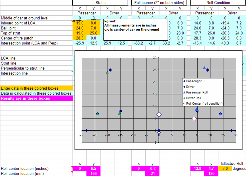
|
|
|
|
| groot |
Dec 1 2004, 08:01 AM
Post
#27
|
|
Dis member Group: Members Posts: 897 Joined: 17-December 03 From: Michigan Member No.: 1,444 |
And now with a simulated lowered 914....
Attached thumbnail(s) 
|
|
|
|
| Jeroen |
Dec 1 2004, 08:31 AM
Post
#28
|
|
914 Guru Group: Members Posts: 7,887 Joined: 24-December 02 From: The Netherlands Member No.: 3 Region Association: Europe |
|
|
|
|
| groot |
Dec 1 2004, 08:38 AM
Post
#29
|
|
Dis member Group: Members Posts: 897 Joined: 17-December 03 From: Michigan Member No.: 1,444 |
Maybe some more explanation would help...
The chart shows a head-on view of the critical points of the front suspension. Starting from the left and working to the right. Lower left corner-center of the tire patch Lower left corner, a little higher-bottom of strut/attachment point of the lower control arm to the strut Upper left-top of strut Middle left-inboard point of lower control arm Everything is repeated on the other side of the zero line You see multiple points at each spot because I plotted the static and roll condition. |
|
|
|
| Nick |
Dec 1 2004, 09:24 AM
Post
#30
|
|
Member Group: Members Posts: 144 Joined: 25-June 04 From: Washington DC Member No.: 2,250 |
I'm reading this thread and wondering if anyone has a book recomendation for suspension 101 type stuff. I don't even have enough suspension vocab to completely follow this thread.
|
|
|
|
| groot |
Dec 1 2004, 09:38 AM
Post
#31
|
|
Dis member Group: Members Posts: 897 Joined: 17-December 03 From: Michigan Member No.: 1,444 |
The Carrol Smith books are a great start.
From there you can go to: -Gillespie's Vehicle Dyanamics -Milliken's Race Car Vehicle Dynamics -Paul Haney's The Racing and High Performance Tire There's plenty more.... |
|
|
|
| jwalters |
Dec 1 2004, 09:43 AM
Post
#32
|
|
Sooo Close....... Group: Members Posts: 1,677 Joined: 14-May 04 From: Huntsville, AL Member No.: 2,068 Region Association: Europe |
(IMG:style_emoticons/default/smilie_pokal.gif) You know what somebody needs to do--is design new pick-up points for the arms that use the same type of adjuster as seen on many crotch rockets, you know, the round one which you turn in a desired direction for chain tension and ride height---if someone were to design these into the pick-up points with a bearing action--when the arm moves thru its travel, the geometry would be locked in place solid (IMG:style_emoticons/default/beer.gif) (IMG:style_emoticons/default/beer.gif) (IMG:style_emoticons/default/beer.gif)
|
|
|
|
| TimT |
Dec 1 2004, 09:49 AM
Post
#33
|
|
retired Group: Members Posts: 4,033 Joined: 18-February 03 From: Wantagh, NY Member No.: 313 |
FWIW i just read in Paul Freres book "Porsche race cars of the 1970's"
that the 917/30 had a CG of 15" |
|
|
|
| Brett W |
Dec 1 2004, 10:50 AM
Post
#34
|
|
Advanced Member Group: Members Posts: 2,859 Joined: 17-September 03 From: huntsville, al Member No.: 1,169 Region Association: None |
Those books that Kevin listed are considered by most in the industry as the emminent sources for this type of info.
For the rest of you guys that aren't interested in the formulas and major engineering text. Get: How to Make Your Car Handle by Fred Puhn Chassis Engineering by Herb Adams Race Car Engineering by Paul Vanvalkenburg Although a little older in material, they are easily understood and won't put you to sleep right away. Once you read these and decide that they can no longer explain the finer points of this complex study. Then pick up the books that Kevin listed. They will help with the true nuts and bolts of what really happens. The offset busings for the rear are an idea that was proposed before. Tough to manufacture for our situation. |
|
|
|
| groot |
Dec 1 2004, 02:57 PM
Post
#35
|
|
Dis member Group: Members Posts: 897 Joined: 17-December 03 From: Michigan Member No.: 1,444 |
The moveable suspension pickup points is in theory a great idea, but difficult to implement. Not impossible, just difficult. Those adjusters you mentioned would be great on the rear suspension to adjust toe.
I wanted to make my front lower control arm points height adjustable, so I could change the roll center as conditions ditacted (like for rain, to soften the weight transfer). But, in the end I decided to get the car on track and maybe change it later. I made it all so incredibly beefy an wee little adjustor like that would be the weakest point. |
|
|
|
| smrz914 |
Dec 1 2004, 11:37 PM
Post
#36
|
|
Soon to be brightening the life of the person behind you. Group: Members Posts: 456 Joined: 21-April 03 From: Pleasant Hill, CA or Chico, CA Member No.: 596 |
For those of us that like engineering, cars, but are visual learners can somone make up some simple diagrams that show what you guys are talking about? maybe even have 914 parts in the drawings. Thanks
|
|
|
|
| jwalters |
Dec 2 2004, 07:43 AM
Post
#37
|
|
Sooo Close....... Group: Members Posts: 1,677 Joined: 14-May 04 From: Huntsville, AL Member No.: 2,068 Region Association: Europe |
QUOTE(groot @ Dec 1 2004, 12:57 PM) The moveable suspension pickup points is in theory a great idea, but difficult to implement. Not impossible, just difficult. Those adjusters you mentioned would be great on the rear suspension to adjust toe. I wanted to make my front lower control arm points height adjustable, so I could change the roll center as conditions ditacted (like for rain, to soften the weight transfer). But, in the end I decided to get the car on track and maybe change it later. I made it all so incredibly beefy an wee little adjustor like that would be the weakest point. (IMG:style_emoticons/default/wink.gif) All depends on the material of choice---A one inch thick by 2.5 inch diameter chunk of stainless will be strong enough to lift a 40 ton cat bulldozer welded to it---would easily take on the teener. These have actually been implemented in years of past, ever hear of a motorbike called a "BIMOTA". Early eighties they made a model called the " TESI" it had a front and rear swingarm, no forks as conventional even unto this day. Bimota solved the problem of toe changes in the front swingarm by using those same eccentric adjusters--not to boot that after they invented it first, almost every bike manufacturer went with them for adjusting the rear wheel!!! Too bad the technology did not take hold, people freaked at the sight of a front swingarm motorbike---but when Bimota raced it, even down on power, NOTHING could touch it in the twisties!!! (IMG:style_emoticons/default/beer.gif) (IMG:style_emoticons/default/beer.gif) |
|
|
|
| groot |
Dec 2 2004, 08:23 AM
Post
#38
|
|
Dis member Group: Members Posts: 897 Joined: 17-December 03 From: Michigan Member No.: 1,444 |
Oh, I know what you're talking about now. Those eccentrics are used quite often on cars these days, when they care about adjustment. My Focus had them on the rear suspension links. They are very common on Mazda cars, since Mazda designs in adjustability.
With longer lower control arms, you actually have to move the mount a fair bit (at least an inch) to get the desired effect. I thought you were talking about the screw adjustors that are used to adjust chain tension. My bad. BTW... BMW has some morphed version of a swing arm on their bikes. It's quite intriguing. |
|
|
|
| slivel |
Dec 2 2004, 09:26 AM
Post
#39
|
|
Old car....... older driver Group: Members Posts: 543 Joined: 10-July 04 From: San Diego Member No.: 2,332 Region Association: Southern California |
QUOTE(groot @ Nov 29 2004, 07:40 AM) Angled down towards the wheel (better than parallel) to the ground is a decent rule of thumb, but .... see my signature..... You can always just drive it and have fun (IMG:style_emoticons/default/wink.gif) and not stress about it. If the roll center is too low, you just need more roll stiffness to counter it. I think that's why there are so many big ARBs for the 914. Since I know I'm not Montoya I need to build a car that is easier to drive and I like the engineering exercise behind it all. Kevin, Right now my front arms are roughly parallel to the ground. To adjust the roll center by angling the front up and down in the rear (towards the wheel) don't you wind up causing a binding in the pivot points. The crossmenber doesn't seem to allow much in the way of latitude here. Do you make some mod to either end of the suspension arm to allow the repositioning without binding? Additionally this may change the roll center but doesn't this now cause the arc of the wheel to be other than vertical under suspension travel? Steve (IMG:style_emoticons/default/confused24.gif) |
|
|
|
| groot |
Dec 2 2004, 10:00 AM
Post
#40
|
|
Dis member Group: Members Posts: 897 Joined: 17-December 03 From: Michigan Member No.: 1,444 |
|
|
|
|
|
1 User(s) are reading this topic (1 Guests and 0 Anonymous Users)
0 Members:

|
Lo-Fi Version | Time is now: 18th March 2026 - 11:55 AM |
Invision Power Board
v9.1.4 © 2026 IPS, Inc.