|
|
|
Porsche, and the Porsche crest are registered trademarks of Dr. Ing. h.c. F. Porsche AG.
This site is not affiliated with Porsche in any way. Its only purpose is to provide an online forum for car enthusiasts. All other trademarks are property of their respective owners. |
|
|

  |

| timothy_nd28 |
 Aug 11 2013, 05:42 PM Aug 11 2013, 05:42 PM
Post
#1
|
|
Advanced Member  Group: Members Posts: 2,299 Joined: 25-September 07 From: IN Member No.: 8,154 Region Association: Upper MidWest |
First I would like to give thanks to Terry, my uncle, for his time on this and my other RGB backlighting project. He has spent more time working on this than he cares to admit. He's more of a Corvette guy, but his vast knowledge and willingness to help, transcends which benefits our community.
Okay, so I have been told that our tachometer has a problem with bouncing. I personally have never seen this problem and I have to admit that I've never really paid much attention to the tach while driving, so I decided to put the signal generator on the tach and see how it performs. This signal generator bypasses the ignition system and provides a clean signal. This also serves as a control because a bad condenser on the dizzy can cause problems as well. This video shows the untouched tach in its original state running on a function generator. As you will see, it does bounce and over shoot during the sweeps. https://www.youtube.com/watch?v=rbC37l1z_oA This next video shows our tach but with a cheap modern 30 dollar tach stuffed inside. The bounce seems to have disappeared, and there is no more overshoot during the sweeps. https://www.youtube.com/watch?v=cmk1lSop_iE The VDO tach was designed for mass production and had a very simple but effective design. This modern tach uses an air core massless motor which is controlled by sine/cosine inputs which tends to be a bit more responsive and accurate. The original vdo design is a motor/spring contraption which will always have some bounce. Over time, capacitors and dampening fluid may leak or fatigue which will aggravate the problem. In this write up, I will show how to incorporate a off the shelf 30 dollar tachometer commonly found at the auto parts store, and make it work with our VDO gauge can. |
   |

 
|
| timothy_nd28 |
Aug 11 2013, 05:42 PM
Post
#2
|
|
Advanced Member Group: Members Posts: 2,299 Joined: 25-September 07 From: IN Member No.: 8,154 Region Association: Upper MidWest |
First we need to purchase this cheap 30 dollar tach. I have found them readily available at AutoZone.
This write up will implicitly describe how to use this style tach. 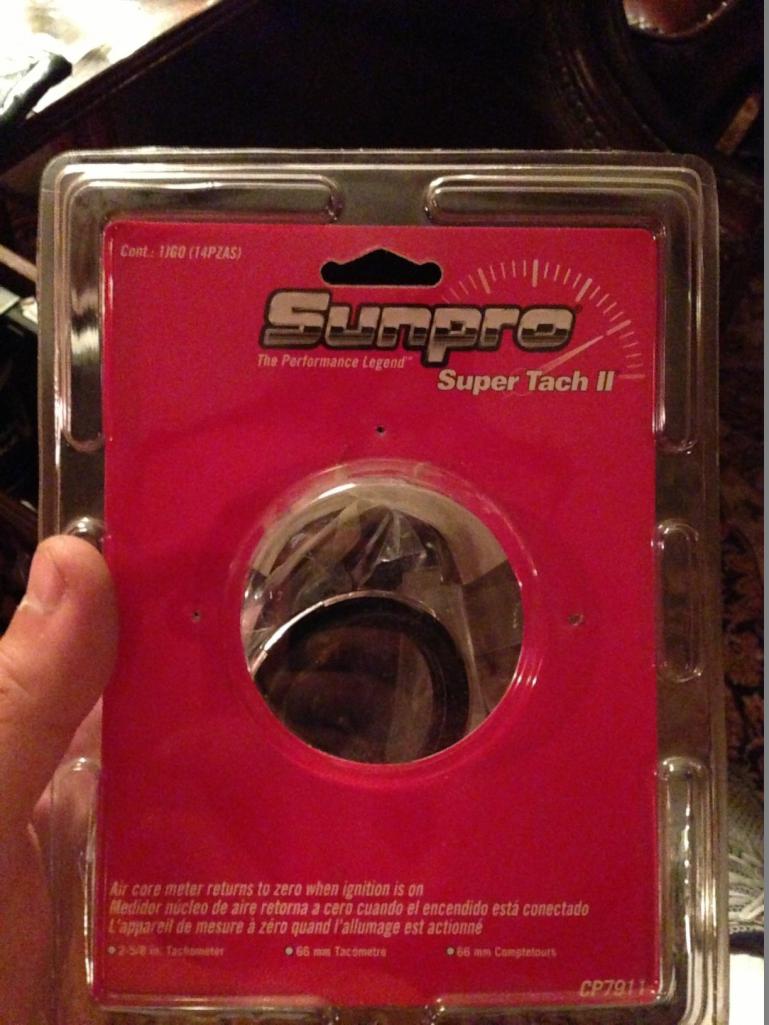 After buying this tach, go ahead and disassemble it. On the circuit board you will need to look for a revision letter. We are looking for revision letter D, if it's not a D go ahead and reassemble the tach and trade it in for another. Rev A has some problems, and is actually quite different than the D. The shaft size for the needle is smaller than rev D and the electronic layout seems to be dramatically different as well. The picture below shows the revision letter on the circuit board. 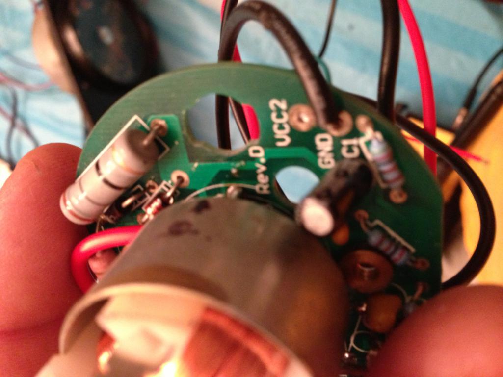 Next, we will need to remove the selector switch on the back of the circuit board. This selector switch, switches from 4 to 6 to 8 cylinders. This switch will be in the way and hits the back of the gauge can. You can either de-solder this switch, or you can use diagonal cutters to snip the leads. After you have removed the selector switch, you will need to solder in a jumper wire as shown in the picture below. 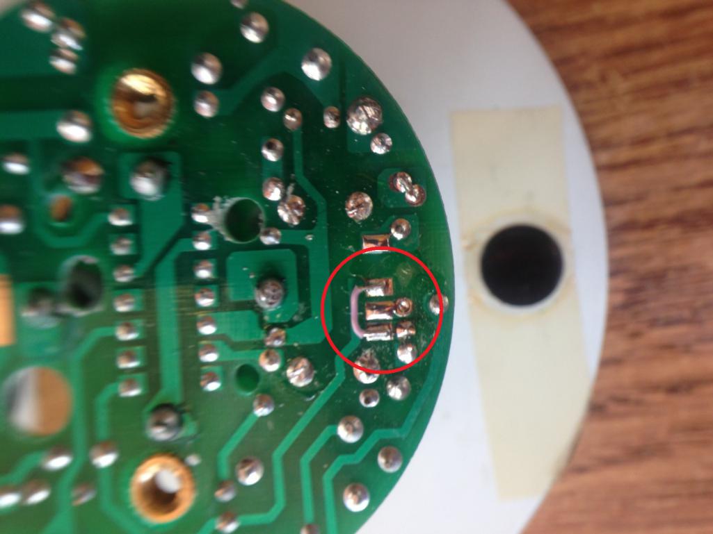 |
|
|
|
| timothy_nd28 |
Aug 11 2013, 05:42 PM
Post
#3
|
|
Advanced Member Group: Members Posts: 2,299 Joined: 25-September 07 From: IN Member No.: 8,154 Region Association: Upper MidWest |
After the jumper has been soldered, we need to change out a resistor (R9). R9 is shown in the picture below.
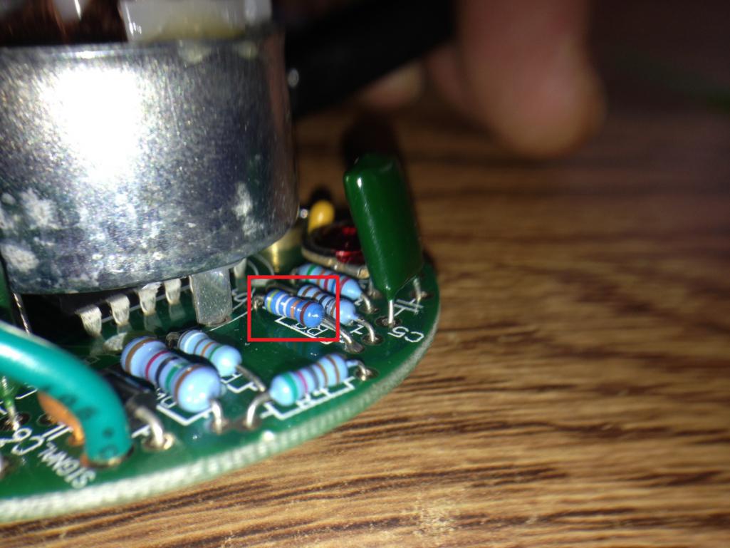 So remove the current resistor in this location and replace it with a 499k ohm resistor. The reason why this must be done, you will notice that our VDO tach face has the tic marks at certain RPM's and different degree marks than the 30 dollar tach. The VDO face dial is 4 some inches in diameter, and the sunpro tach has a tiny 1.5 inch dial face. The numbers for each RPM simply don't line up, so changing the resistor will fix the gain on the needle sweep and correct with the corresponding angle. 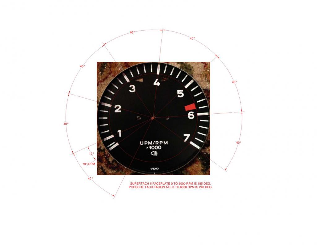 This resistor has been carefully calculated for solving this problem at no extra charge to you! (IMG:style_emoticons/default/biggrin.gif) However tips are appreciated! (IMG:style_emoticons/default/slap.gif) Edit: R9 resistor values: 499k ohm for a 4 cylinder 340k ohm for a 6 cylinder 243k ohm for a 8 cylinder Now go ahead and cut the white wire near the circuit board. This wire is used for lighting, which you will not need for this project. You will also need to pull all the other wires so they come thru the top of the circuit board. If you leave the wires where they are at, the circuit board will stick too far out from the back of the gauge can. It should look something like this when you are done. Go ahead and zip tie the wires to the hole in the circuit board. This will be a good strain relief for the mice that might be pulling on the wires under your dash. 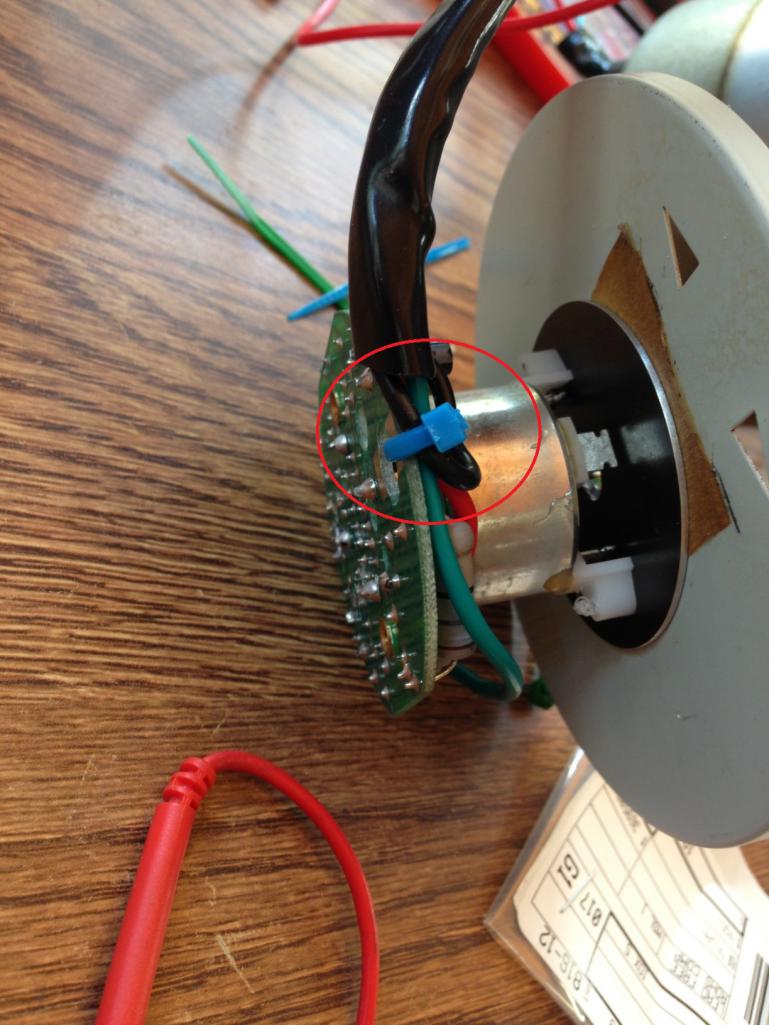 The electrical portion of this build is now complete. The backside of the circuit board is very clean with no wires in the way. The circuit board should sit nicely inside the gauge can. |
|
|
|
| timothy_nd28 |
Aug 11 2013, 05:43 PM
Post
#4
|
|
Advanced Member Group: Members Posts: 2,299 Joined: 25-September 07 From: IN Member No.: 8,154 Region Association: Upper MidWest |
Now the machining part. Go ahead and remove the gauge bezel ring with a small screwdriver. Carefully uncrimp the lip that holds the bezel ring in place. After this ring has been removed, go ahead and remove the glass and the inner bezel ring. Next you'll need to remove the 4 small screws on the back of the can. Next, remove the tach from the can. It should look like this after you are done.
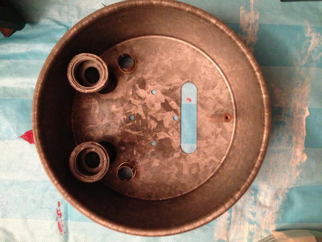 Carefully put aside the tach assembly that you just removed from the can. We will come back to this later. Now obtain a 9/64" drill bit. You will need to enlarge these 2 holes. 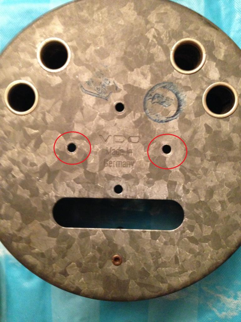 With the holes slightly bigger, you can now use the same screws that came with the 30 dollar tachometer to secure the circuit board inside the VDO can. |
|
|
|
| timothy_nd28 |
Aug 11 2013, 05:43 PM
Post
#5
|
|
Advanced Member Group: Members Posts: 2,299 Joined: 25-September 07 From: IN Member No.: 8,154 Region Association: Upper MidWest |
Now the fun stuff. You will need one of these.
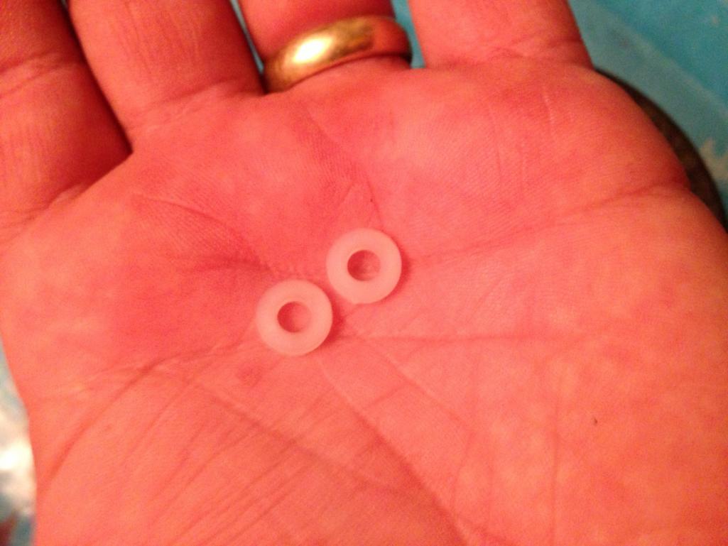
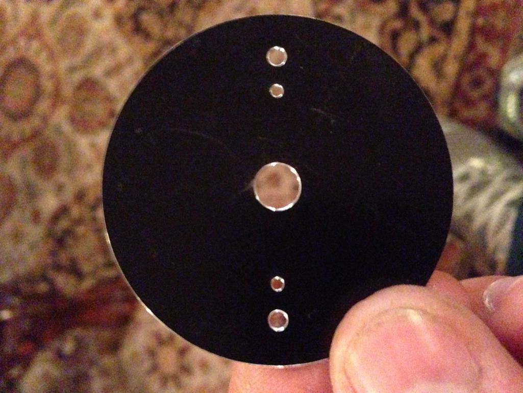 This is a adapter bracket that will mount to the modern circuit board, but will also allow you to mount the 914 face dial to it. Below is the specs for this bracket. Take this drawing to any machine shop, they should have no problem making you one. 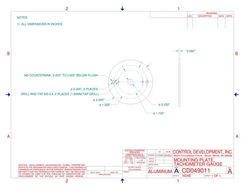 I am very fortunate to have a family member that happens to own a machine shop. This particular bracket was made via a waterjet machine. After you have obtained said bracket, you will need to remove the plastic bracket on the sunpro's motor. See picture below. Remove this bracket and discard of it. 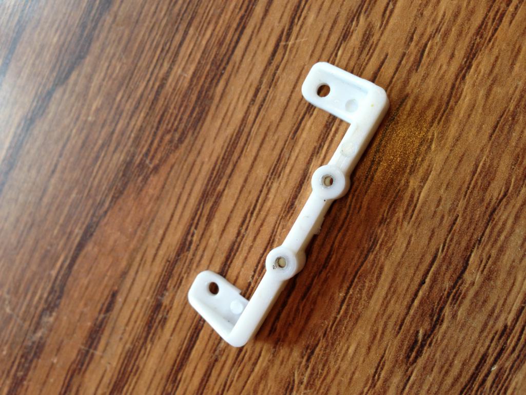 Now grab the old tachometer that you pulled apart earlier. Carefully, (can't stress this enough) pull the needle straight up. Some force might be involved to remove this needle. Next, remove the 2 screws (some have 3) that are on the 914's face dial. With the face dial removed, go ahead and wipe it off and remove any oily finger prints. The sunpro tachometer will need to have its threads re-tapped to accommodate the new screws for the mounting bracket. Use this tap on the sunpro's motor plastic bracket: 8305A77 Metric high speed steel hand tap 2x.4mm, D3 pitch diameter, 3 flute After these 2 holes are re-tapped go ahead and counter sink the 2 holes with this counter sinking bit: 2846A124 Single-Flute high speed steel countersink 90 degree angle, 3/8" body diameter, 1/4" shank diameter. Next, mount the adapter plate on the sunpro tach mounting plate. Use these screws: 91698A202 metric 18-8 stainless steel flat head phillips machine screw black-oxide M2 size, 6mm length, .4mm pitch. Make sure the holes on the adapter plate are counter sunk, and the screws are flush with this bracket. Now mount the 914 face dial to the adapter plate. You can re-use your old screws if they aren't too scratched up. Or you can use these screws: 95836A105 metric pan head phillips machine screw black-oxide 18-8 stainless steel M2 size, 4mm length, .4mm pitch It should start looking pretty good. You should now have the modern circuit board mounted to the 914 face dial. There is one last thing you'll need to do with machining, the needle. The needle won't simply push back on the shaft. You will need to drill the hole a size bigger. Obtain a 0.037" drill bit, and chuck it up to a dremil. After the needle has been honed out, hold off from re-installing the needle. We will need to calibrate it first. So now we need to assemble this back into the can. Use this hole to loom the wires thru the back of the can. 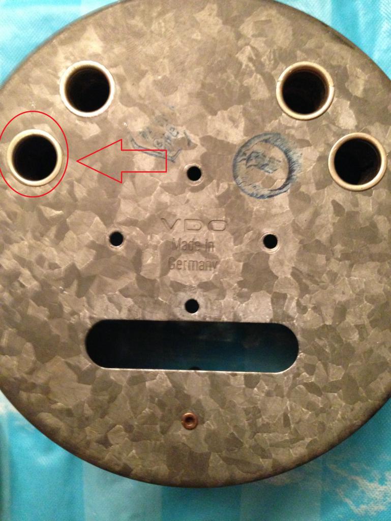 This mod was intended to re-use holes and doesn't require you to drill new ones which will ruin your gauge can. If you use this hole, you will lose one light port for your tach. This is a great time to upgrade to LED lighting. See my topic "custom gauge backlighting" for further explanation. This is a picture with the wires running thru the back of the gauge can 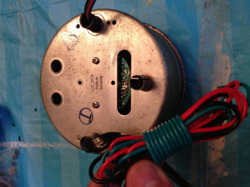 Put a couple nylon washers between the back of the gauge can and the circuit board. This spaces the circuit board, so nothing shorts out. I ended up using 2 nylon washers per screw. |
|
|
|
| timothy_nd28 |
Aug 11 2013, 08:26 PM
Post
#6
|
|
Advanced Member Group: Members Posts: 2,299 Joined: 25-September 07 From: IN Member No.: 8,154 Region Association: Upper MidWest |
 Now we need to apply power to this. The red and black wire goes to the battery. The green wire goes to the black/purple striped wire. This will be a very crude calibration technique, but if you don't have access to a function generator this will do. Applying power will zero the shaft, this is why powering up is so essential. Now pay close attention to the picture below. 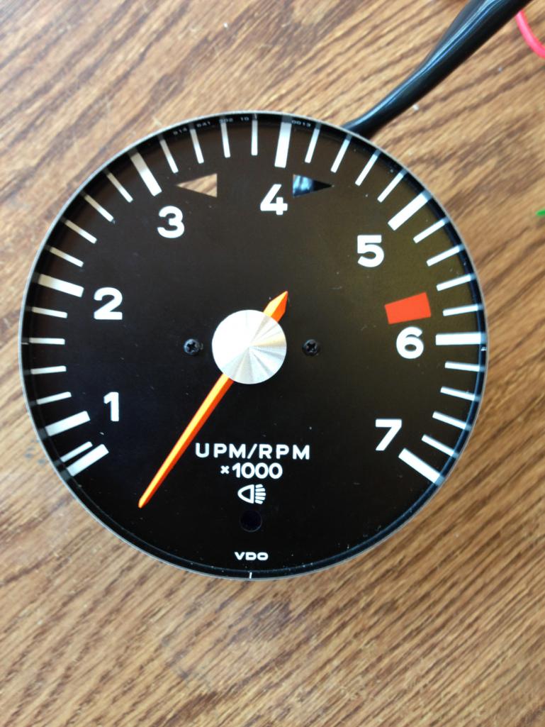 Put the needle back onto the shaft at this same spot. This should get you very close to correct. Reinstall the glass and bezel ring and enjoy! (IMG:style_emoticons/default/beerchug.gif) |
|
|
|
| Dave_Darling |
Aug 11 2013, 10:04 PM
Post
#7
|
|
914 Idiot Group: Members Posts: 15,353 Joined: 9-January 03 From: Silicon Valley / Kailua-Kona Member No.: 121 Region Association: Northern California |
Very cool! Have you verified this with the points-and-condensor setup that the 914s run? Modern signals may be significantly cleaner than the signal that the old 914 setup generates.
--DD |
|
|
|
| timothy_nd28 |
Aug 11 2013, 10:42 PM
Post
#8
|
|
Advanced Member Group: Members Posts: 2,299 Joined: 25-September 07 From: IN Member No.: 8,154 Region Association: Upper MidWest |
QUOTE(Dave_Darling @ Aug 11 2013, 08:04 PM)  Very cool! Have you verified this with the points-and-condensor setup that the 914s run? Modern signals may be significantly cleaner than the signal that the old 914 setup generates. --DD Never mind my noisy valve lash adjustment (IMG:style_emoticons/default/dry.gif) ***my 914 shown in this video has a stock ignition points/coil setup*** https://www.youtube.com/watch?v=fPk_A1PzbuY |
|
|
|
| monkeyboy |
Aug 11 2013, 11:06 PM
Post
#9
|
|
Senior Member Group: Members Posts: 808 Joined: 8-June 08 From: Los Angeles, Ca Member No.: 9,147 Region Association: None |
Wow. Thank you for the amazing work.
Will the new tach internals still accept the stock tach input? I have one of those funny MSD tach sensing adaptors to adopt my stock tach to work with my computerized ignition. I'd guess I leave it as it is? |
|
|
|
| mikelsr |
Aug 11 2013, 11:09 PM
Post
#10
|
|
Senior Member Group: Members Posts: 657 Joined: 2-January 05 From: Mahomet, IL Member No.: 3,390 Region Association: Southwest Region |
Looks really nice and thanks for the work. Do you know if it will with the CDI ignition on a -6? (yes I know you have to jumper it for a 6)
|
|
|
|
| timothy_nd28 |
Aug 11 2013, 11:32 PM
Post
#11
|
|
Advanced Member Group: Members Posts: 2,299 Joined: 25-September 07 From: IN Member No.: 8,154 Region Association: Upper MidWest |
Here's the manual for this unit tach manual
It works with the stock point/ignition coil signal setup. It will also work with the modern 5volt systems. This is the beauty of using a true universal tach! lol This write up was for the 4 cylinder cars. Calculations are needed for using this on a 6 cylinder. R9 will change value slightly, most likely a 340k resistor. |
|
|
|
| Chris H. |
Aug 12 2013, 08:30 AM
Post
#12
|
|
Senior Member Group: Members Posts: 4,090 Joined: 2-January 03 From: Chicago 'burbs Member No.: 73 Region Association: Upper MidWest |
How much for you to do it Tim? Not sure how bouncy mine will be with the subie but I will know very soon. I'm sure everyone is wondering...
|
|
|
|
| timothy_nd28 |
Aug 12 2013, 11:26 AM
Post
#13
|
|
Advanced Member Group: Members Posts: 2,299 Joined: 25-September 07 From: IN Member No.: 8,154 Region Association: Upper MidWest |
QUOTE(Chris H. @ Aug 12 2013, 06:30 AM) How much for you to do it Tim? Not sure how bouncy mine will be with the subie but I will know very soon. I'm sure everyone is wondering... I'm currently offering a service for upgrading our gauges to the RGB led backlighting. I'm thinking about offering this as an add on service for those that will have me perform the labor. As of right now, I was thinking of charging an additional 100 dollars to do this tach conversion |
|
|
|
| ThePaintedMan |
Aug 12 2013, 11:45 AM
Post
#14
|
|
Advanced Member Group: Members Posts: 3,887 Joined: 6-September 11 From: St. Petersburg, FL Member No.: 13,527 Region Association: South East States |
Tim,
You are unstoppable. Nice work man. I like upgrades that are cheap, especially when harnessing newer technology. (IMG:style_emoticons/default/beerchug.gif) |
|
|
|
| timothy_nd28 |
Aug 12 2013, 03:52 PM
Post
#15
|
|
Advanced Member Group: Members Posts: 2,299 Joined: 25-September 07 From: IN Member No.: 8,154 Region Association: Upper MidWest |
The video below shows the tachometer running on 5volts tach signal.
https://www.youtube.com/watch?v=uUzPC8mEMMI So, testing is complete with this. The tach will work with our stock setup, where the tach signals are greater than 200volts and it will also work with the modern tach 5 volt signals. |
|
|
|
| monkeyboy |
Aug 12 2013, 11:05 PM
Post
#16
|
|
Senior Member Group: Members Posts: 808 Joined: 8-June 08 From: Los Angeles, Ca Member No.: 9,147 Region Association: None |
Now I need a motor that will run through the gears that fast!
|
|
|
|
| McMark |
Aug 13 2013, 12:59 AM
Post
#17
|
|
914 Freak! Group: Retired Admin Posts: 20,180 Joined: 13-March 03 From: Grand Rapids, MI Member No.: 419 Region Association: None |
Just ordered my Sunpro CP7911 off Amazon. This is awesome! Can't wait.
The stock tach doesn't work will with my MicroSquirt without a tach adapter. This solves that problem for me as well. (IMG:style_emoticons/default/boldblue.gif) |
|
|
|
| timothy_nd28 |
Sep 9 2013, 07:41 PM
Post
#18
|
|
Advanced Member Group: Members Posts: 2,299 Joined: 25-September 07 From: IN Member No.: 8,154 Region Association: Upper MidWest |
QUOTE(McMark @ Aug 12 2013, 10:59 PM) Just ordered my Sunpro CP7911 off Amazon. This is awesome! Can't wait. The stock tach doesn't work will with my MicroSquirt without a tach adapter. This solves that problem for me as well. (IMG:style_emoticons/default/boldblue.gif) Any progress? What version tach did you get from Amazon? (IMG:style_emoticons/default/popcorn[1].gif) |
|
|
|
| McMark |
Oct 15 2013, 08:58 PM
Post
#19
|
|
914 Freak! Group: Retired Admin Posts: 20,180 Joined: 13-March 03 From: Grand Rapids, MI Member No.: 419 Region Association: None |
Got it modded and installed. Had to order the 499k resistor from Mouser. Now I just need to swap in the MicroSquirt brain that doesn't have a fried tach output. (IMG:style_emoticons/default/wink.gif)
|
|
|
|
| timothy_nd28 |
Oct 15 2013, 09:40 PM
Post
#20
|
|
Advanced Member Group: Members Posts: 2,299 Joined: 25-September 07 From: IN Member No.: 8,154 Region Association: Upper MidWest |
Nice. One minor flaw has been found with this retrofit. The ground wire which attached to the tach was also grounded the the gauge can internally. You will need to find a way to ground the gauge can, or funky things will happen with the indicator lights.
I have recently found a way to re-use the original terminal block with this upgrade, which retains the proper grounding of the gauge can. |
|
|
|
|
1 User(s) are reading this topic (1 Guests and 0 Anonymous Users)
0 Members:

|
Lo-Fi Version | Time is now: 8th July 2026 - 11:42 AM |
Invision Power Board
v9.1.4 © 2026 IPS, Inc.