|
|
|
Porsche, and the Porsche crest are registered trademarks of Dr. Ing. h.c. F. Porsche AG.
This site is not affiliated with Porsche in any way. Its only purpose is to provide an online forum for car enthusiasts. All other trademarks are property of their respective owners. |
|
|

  |

| Steve_R |
 Oct 3 2020, 11:52 AM Oct 3 2020, 11:52 AM
Post
#1
|
|
Member  Group: Members Posts: 68 Joined: 8-August 12 From: San Diego, CA Member No.: 14,777 Region Association: None |
Hi everyone,
About 4 years ago I designed and built a solid state relay board for my 914. I built a few extra ones and you can read all about that HERE. After building those I realized that not everybody wants solid state relays. So, I designed a version that uses the stock electromechanical relays. I started building a batch of 10 and I got distracted with another project. Recently, I had some more time and I completed those. This relay board uses the stock relays for power, heater and fuel pump. There are no provisions for the rear window heater. The relay socket used for the window heater is used to store an extra relay. This board uses an ATC style fuse and has an LED that illuminates when the relay board is supplying power to the fuel pump. This is useful in diagnosing fuel pump issues. The LED illuminates for about 2 seconds when the key is turned on and remains illuminated when the engine is running. I am selling this last batch for $325.00 each. This board does not come with any relays or the voltage regulator. I’ll cover the shipping and sorry, I can’t ship international. Message me if you want one. No need to reply to this post. I will edit this post and remove this section when they are all gone. Okay, with that said, I will not be making any more of these. I will be making this design available to the 914 World Community. I have attached the 3D solid models (in STEP format) to the next post. Also, I attached a PowerPoint (PDF format) that outlines the construction process as well as the sources for all of the parts. There are 3D models for the solid state relay version as well as the stock electromechanical relay version. This design and associated files is completely open source and can be used by anyone for any reason. These boards are designed to be CNC machined from plastic. I used a CNC VMC. However, I think a CNC router would also work. I don’t think a 3D printer would work with the current design. However, I it could easily be modified to work. Attached image(s) 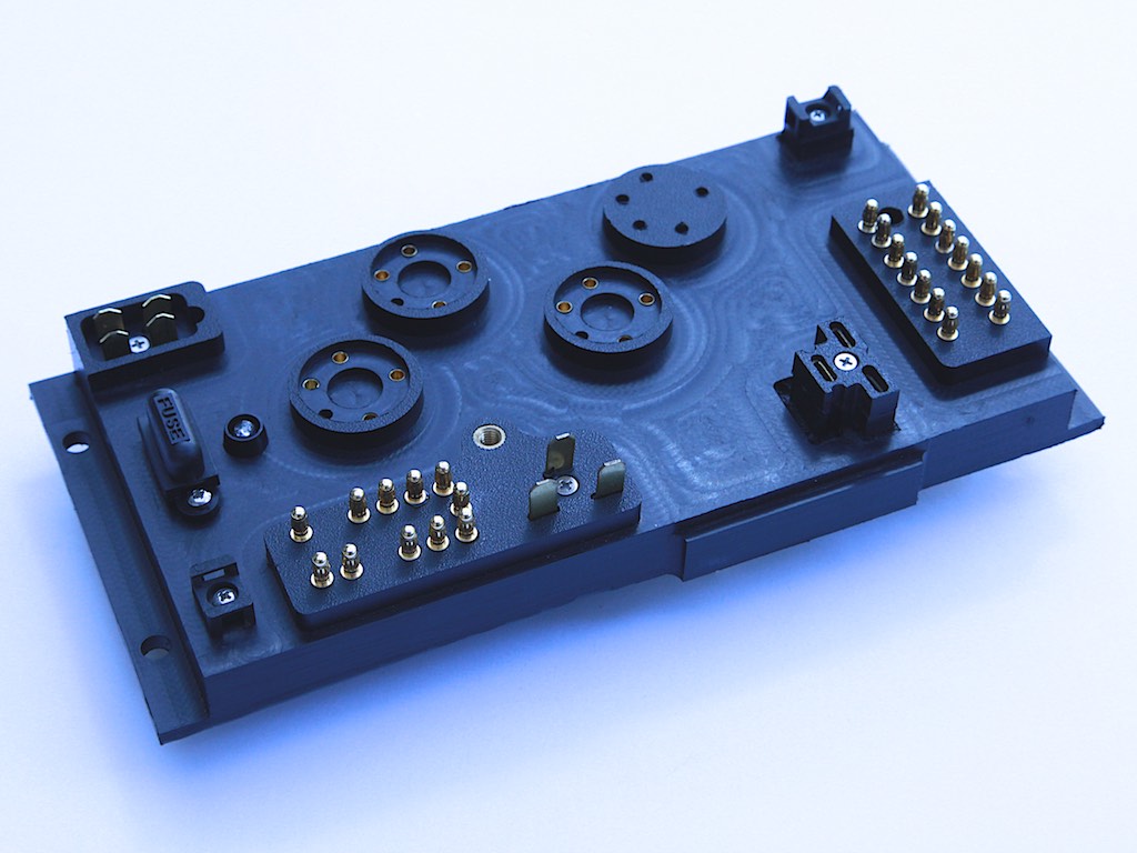
|
   |

 
|
| Steve_R |
Oct 3 2020, 11:58 AM
Post
#2
|
|
Member Group: Members Posts: 68 Joined: 8-August 12 From: San Diego, CA Member No.: 14,777 Region Association: None |
3D Models.
I am not able to upload cad files to this site so I put them on my GrabCAD page. https://grabcad.com/library/porsche-914-relay-board-1 |
|
|
|
| Steve_R |
Oct 3 2020, 11:59 AM
Post
#3
|
|
Member Group: Members Posts: 68 Joined: 8-August 12 From: San Diego, CA Member No.: 14,777 Region Association: None |
Construction Details.
Attached File(s)  914_Relay_Board.pdf ( 3.25mb )
Number of downloads: 114
914_Relay_Board.pdf ( 3.25mb )
Number of downloads: 114 |
|
|
|
| Mikey914 |
Oct 3 2020, 12:51 PM
Post
#4
|
|
The rubber man Group: Members Posts: 12,772 Joined: 27-December 04 From: Hillsboro, OR Member No.: 3,348 Region Association: None |
Would be happy to make a large run of these for those that want them and even add relays at a reduced cost.
Thinking keep the cost low znd just do mass production on the machined oarts, maybe do a kit? |
|
|
|
| DRPHIL914 |
Oct 3 2020, 12:54 PM
Post
#5
|
|
Dr. Phil Group: Members Posts: 5,907 Joined: 9-December 09 From: Kennesaw, GA Member No.: 11,106 Region Association: South East States |
QUOTE(Mikey914 @ Oct 3 2020, 02:51 PM)  Would be happy to make a large run of these for those that want them and even add relays at a reduced cost. interested |
|
|
|
| Jett |
Oct 3 2020, 09:03 PM
Post
#6
|
|
Senior Member Group: Members Posts: 1,697 Joined: 27-July 14 From: Seattle Member No.: 17,686 Region Association: Pacific Northwest |
How about adding the rear defrost connection?
|
|
|
|
| JeffBowlsby |
Oct 3 2020, 09:25 PM
Post
#7
|
|
914 Wiring Harnesses & Beekeeper Group: Members Posts: 9,221 Joined: 7-January 03 From: San Ramon CA Member No.: 104 Region Association: None |
As admirable as this design and effort is, I see an issue on the wiring list.
The wire re: connection 1 is the circuit for the starter solenoid from the ignition switch. It needs to be a 10 ga wire not 14 gage. Also, with the discrete wires as circuits why not just affix a gasketed, removable bottom plate instead of the potting compound? |
 |
|
| Mikey914 |
Oct 3 2020, 09:57 PM
Post
#8
|
|
The rubber man Group: Members Posts: 12,772 Joined: 27-December 04 From: Hillsboro, OR Member No.: 3,348 Region Association: None |
QUOTE(Jett @ Oct 3 2020, 08:03 PM) How about adding the rear defrost connection? Could be done, just need to machine it |
|
|
|
| Steve_R |
Oct 3 2020, 10:15 PM
Post
#9
|
|
Member Group: Members Posts: 68 Joined: 8-August 12 From: San Diego, CA Member No.: 14,777 Region Association: None |
QUOTE(JeffBowlsby @ Oct 3 2020, 08:25 PM) As admirable as this design and effort is, I see an issue on the wiring list. The wire re: connection 1 is the circuit for the starter solenoid from the ignition switch. It needs to be a 10 ga wire not 14 gage. Also, with the discrete wires as circuits why not just affix a gasketed, removable bottom plate instead of the potting compound? I updated the wire list to the 10 ga wire for connection 1. |
|
|
|
| raynekat |
Oct 4 2020, 10:40 PM
Post
#10
|
|
Advanced Member Group: Members Posts: 2,171 Joined: 30-December 14 From: Coeur d'Alene, Idaho Member No.: 18,263 Region Association: Pacific Northwest |
Wish this was available for the 914-6 relay panel as well.
I'd buy it. |
|
|
|
| Superhawk996 |
Oct 5 2020, 06:38 AM
Post
#11
|
|
914 Guru Group: Members Posts: 7,767 Joined: 25-August 18 From: Woods of N. Idaho Member No.: 22,428 Region Association: Galt's Gulch |
Would be great to have a the solid state alternative to OEM board. |
|
|
|
| GregAmy |
Oct 5 2020, 08:11 AM
Post
#12
|
|
Advanced Member Group: Members Posts: 2,651 Joined: 22-February 13 From: Middletown CT Member No.: 15,565 Region Association: North East States |
QUOTE(Mikey914 @ Oct 3 2020, 02:51 PM) Would be happy to make a large run of these for those that want them and even add relays at a reduced cost. Mark, I'd be interested if you could get the volume up enough to get the price down. And offering as an assembly kit would be a good idea to reduce price. GA P.S., don't forget I still have your borrowed OE relay plate in my street car... |
|
|
|
| ClayPerrine |
Oct 5 2020, 08:52 PM
Post
#13
|
|
Life's been good to me so far..... Group: Admin Posts: 16,542 Joined: 11-September 03 From: Hurst, TX. Member No.: 1,143 Region Association: NineFourteenerVille |
How hard would it be to make this up to use the standard square bosch relays? They are available in both electro-mechanical and solid state, so you would only need to make one.
Clay |
|
|
|
| Mikey914 |
Oct 6 2020, 10:46 AM
Post
#14
|
|
The rubber man Group: Members Posts: 12,772 Joined: 27-December 04 From: Hillsboro, OR Member No.: 3,348 Region Association: None |
Not too hard to change up, but why? The new relays are bullet proof and not that expensive for one you'll never have to replace.
|
|
|
|
| johnorm |
Oct 6 2020, 11:22 AM
Post
#15
|
|
Newbie Group: Members Posts: 28 Joined: 28-October 18 From: Canada Member No.: 22,610 Region Association: Canada |
QUOTE(Mikey914 @ Oct 3 2020, 11:51 AM) Would be happy to make a large run of these for those that want them and even add relays at a reduced cost. Thinking keep the cost low znd just do mass production on the machined oarts, maybe do a kit? Mike, for us guys in Canada I would appreciate it if you or another supplier would build us a copy that could be shipped to Canada. |
|
|
|
| Mueller |
Oct 6 2020, 11:29 AM
Post
#16
|
|
914 Freak! Group: Members Posts: 17,155 Joined: 4-January 03 From: Antioch, CA Member No.: 87 Region Association: None |
While I no longer am using the stock relay board on my car I appreciate the time and effort you put into this Steve.
The documentation is 1st class and the willingness to openly share it all helps restore faith in mankind a bit. (IMG:style_emoticons/default/smile.gif) |
|
|
|
| ClayPerrine |
Oct 6 2020, 12:02 PM
Post
#17
|
|
Life's been good to me so far..... Group: Admin Posts: 16,542 Joined: 11-September 03 From: Hurst, TX. Member No.: 1,143 Region Association: NineFourteenerVille |
QUOTE(Mikey914 @ Oct 6 2020, 11:46 AM) Not too hard to change up, but why? The new relays are bullet proof and not that expensive for one you'll never have to replace. Your relays are great. But if I don't have a spare on me, I am SOL. If we use the square Bosch relays, then any FLAPS has them in stock. Even a cheap horn relay could be used in a pinch. |
|
|
|
| johnorm |
Oct 6 2020, 12:13 PM
Post
#18
|
|
Newbie Group: Members Posts: 28 Joined: 28-October 18 From: Canada Member No.: 22,610 Region Association: Canada |
QUOTE(JeffBowlsby @ Oct 3 2020, 08:25 PM) As admirable as this design and effort is, I see an issue on the wiring list. The wire re: connection 1 is the circuit for the starter solenoid from the ignition switch. It needs to be a 10 ga wire not 14 gage. Also, with the discrete wires as circuits why not just affix a gasketed, removable bottom plate instead of the potting compound? Jeff I agree with the 10ga for connection #1 but I have a question on some of the other connections. Based on a current flow diagram I downloaded the majority of the original wire size, for regulatory board, was 0.5mm (18ga) and 1.0mm (16ga.). I'm I wrong to assume a 1.0mm wire converts to a 16ga vs 14ga on Steve's table? |
|
|
|
| JeffBowlsby |
Oct 6 2020, 01:36 PM
Post
#19
|
|
914 Wiring Harnesses & Beekeeper Group: Members Posts: 9,221 Joined: 7-January 03 From: San Ramon CA Member No.: 104 Region Association: None |
0.5 mm^2 converts to 20 gage
1.0 mm^2 converts to 16 gage |
|
|
|
| johnorm |
Oct 6 2020, 01:54 PM
Post
#20
|
|
Newbie Group: Members Posts: 28 Joined: 28-October 18 From: Canada Member No.: 22,610 Region Association: Canada |
QUOTE(JeffBowlsby @ Oct 6 2020, 12:36 PM) 0.5 mm^2 converts to 20 gage 1.0 mm^2 converts to 16 gage Jeff now I'm confused. I checked a number of sites, like Rawell and 2-3 others and their conversion table shows that 1.0mm2 converts up to a 16ga wire which is actually 1.29 to 1.31mm2. The fact that i'm using GXL wire does that a different? Do you have a conversion chart that you could share? Any help would be appreciated. |
|
|
|
|
1 User(s) are reading this topic (1 Guests and 0 Anonymous Users)
0 Members:

|
Lo-Fi Version | Time is now: 1st April 2026 - 01:37 PM |
Invision Power Board
v9.1.4 © 2026 IPS, Inc.