|
|
|
Porsche, and the Porsche crest are registered trademarks of Dr. Ing. h.c. F. Porsche AG.
This site is not affiliated with Porsche in any way. Its only purpose is to provide an online forum for car enthusiasts. All other trademarks are property of their respective owners. |
|
|


| potomacmidget |
 Feb 7 2021, 06:50 PM Feb 7 2021, 06:50 PM
Post
#1
|
|
I gotta have more cowbell....  Group: Members Posts: 161 Joined: 27-March 11 From: Maryland Member No.: 12,860 Region Association: North East States |
Hi -
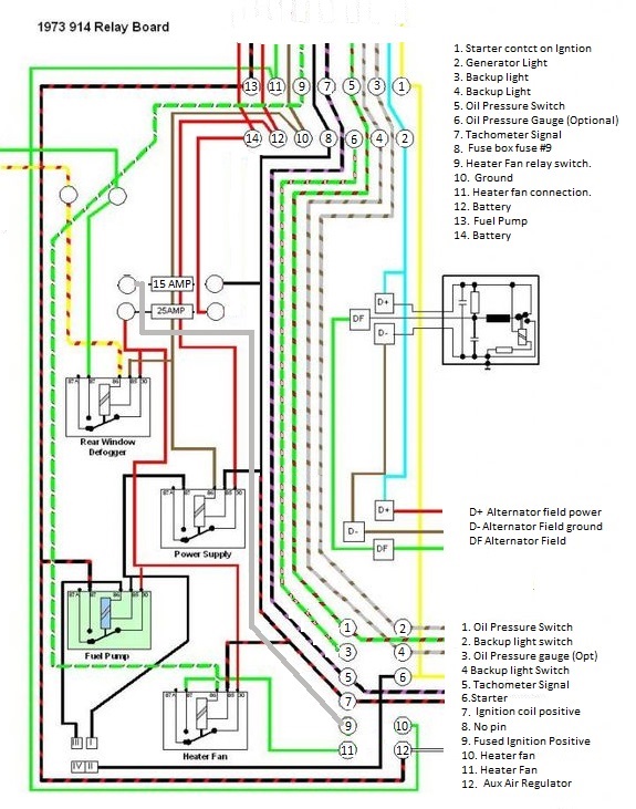
as a winter project I am cleaning up a relay board (removing all the old potting material, etc.) and doing a general clean up. I used the attached drawing from a fellow member (I would give credit but can't remember the thread I saved if from...) and everything seemed to check out minus a couple of findings... For the fuse connections - drawing has F4 connected to C9 - ok, that checked out. For the 12 pin connection it has C9 connected to F3 - but I don't have any continuity. Is that correct or is the schematic wrong? Also for Relay R2 - hole E2 for the 4 pole ECU plug, I get not continuity from the R2 E2 hole to E2 spade connector, but I do get continuity from the E2 hole on the relay plug to the E3 spade on the 4 pole plug. Any advice appreciated - of course the superbowl is on.... thanks, Reg  relay_board_with_notes.pdf ( 3.81mb )
Number of downloads: 52
relay_board_with_notes.pdf ( 3.81mb )
Number of downloads: 52 |
   |

 
|
  |
Replies(1 - 5)
| ClayPerrine |
Feb 7 2021, 07:25 PM
Post
#2
|
|
Life's been good to me so far..... Group: Admin Posts: 15,469 Joined: 11-September 03 From: Hurst, TX. Member No.: 1,143 Region Association: NineFourteenerVille |
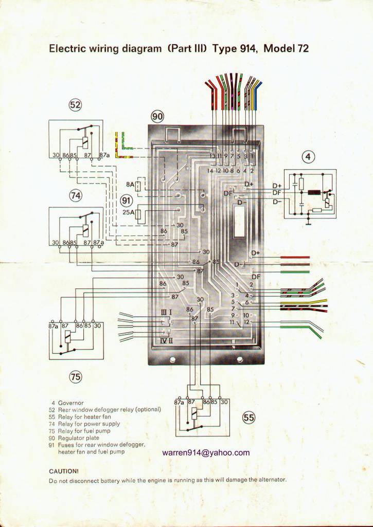
This may help....
 |
|
|
|
| bob164 |
Feb 7 2021, 07:31 PM
Post
#3
|
|
Member Group: Members Posts: 96 Joined: 10-February 18 From: SoCal Member No.: 21,877 Region Association: Southern California |
Here is a recent thread by Clay Perrine that has a much better diagram, hope this helps.
Bob http://www.914world.com/bbs2/index.php?sho...;hl=Relay+board |
|
|
|
| Beebo Kanelle |
Feb 7 2021, 07:33 PM
Post
#4
|
|
Member Group: Members Posts: 248 Joined: 22-November 12 From: Houston, Texas Member No.: 15,177 Region Association: Southwest Region |
I hope this helps. It helped me.
 |
|
|
|
| 914_teener |
Feb 7 2021, 08:36 PM
Post
#5
|
|
914 Guru Group: Members Posts: 5,198 Joined: 31-August 08 From: So. Cal Member No.: 9,489 Region Association: Southern California |
So after you have soaked and cleaned away the old buitumen potting material....clean all the traces throughly.
Then visually check the rivet connections for signs of loosness. I soldered them after cleaning to make sure there are no issues. Took 15 minutes or so. Ring out on your DVM the traces accross the rivets....to check to make sure you are good to go. Then I used a dielectric epoxy potting compound. Make SURE you have blocked out the openings where the potting compund can flow through...IIRC there are several there that will flow through to the topside of the board. Think there are several threads on this as you have discovered. Worked fine after that. |
|
|
|
| potomacmidget |
Feb 9 2021, 04:56 PM
Post
#6
|
|
I gotta have more cowbell.... Group: Members Posts: 161 Joined: 27-March 11 From: Maryland Member No.: 12,860 Region Association: North East States |
QUOTE(914_teener @ Feb 7 2021, 09:36 PM)  So after you have soaked and cleaned away the old buitumen potting material....clean all the traces throughly. Then visually check the rivet connections for signs of loosness. I soldered them after cleaning to make sure there are no issues. Took 15 minutes or so. Ring out on your DVM the traces accross the rivets....to check to make sure you are good to go. Then I used a dielectric epoxy potting compound. Make SURE you have blocked out the openings where the potting compund can flow through...IIRC there are several there that will flow through to the topside of the board. Think there are several threads on this as you have discovered. Worked fine after that. Hi All - thanks for the assistance, I appreciate it - the color drawing already helped me figure out board was ok, but will check all the rivets and repot...thanks again, Best, Reg |
|
|
|
|
1 User(s) are reading this topic (1 Guests and 0 Anonymous Users)
0 Members:

|
Lo-Fi Version | Time is now: 18th May 2024 - 04:00 PM |
Invision Power Board
v9.1.4 © 2024 IPS, Inc.