|
|
|
Porsche, and the Porsche crest are registered trademarks of Dr. Ing. h.c. F. Porsche AG.
This site is not affiliated with Porsche in any way. Its only purpose is to provide an online forum for car enthusiasts. All other trademarks are property of their respective owners. |
|
|

  |

| Tom1394racing |
 May 11 2024, 05:55 AM May 11 2024, 05:55 AM
Post
#341
|
|
Member  Group: Members Posts: 493 Joined: 25-August 07 From: CT Member No.: 8,039 Region Association: North East States |
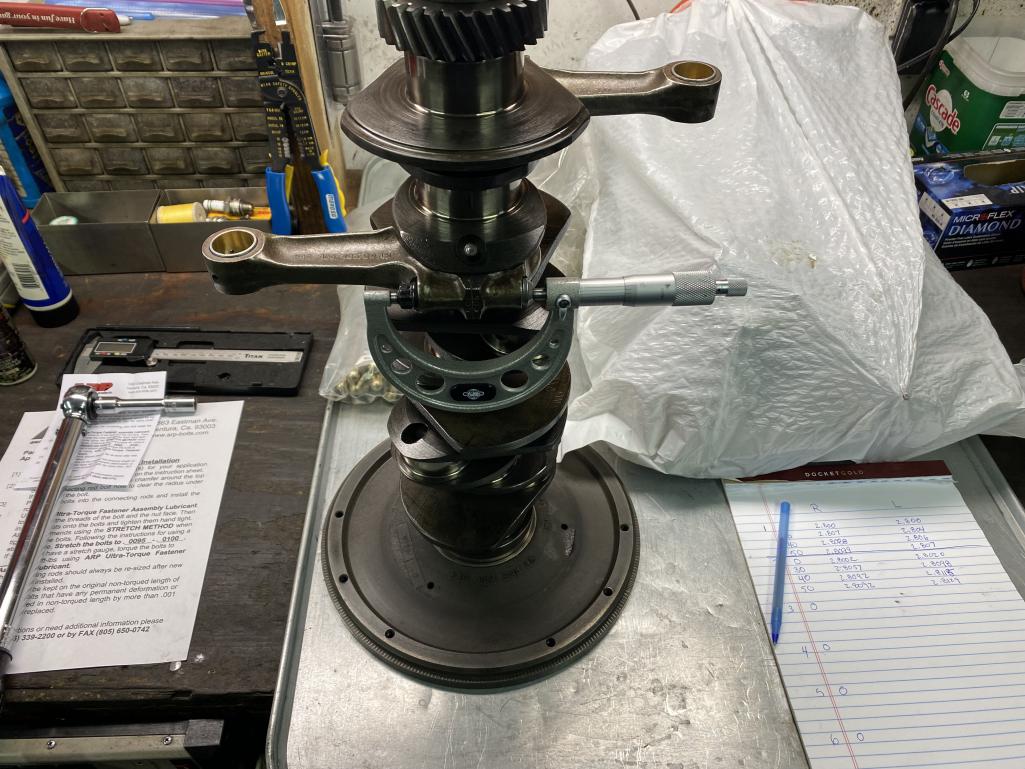
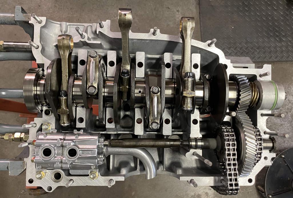
Finally got my rods back from Ollies. They did a nice job balancing them so that each rod is within 1/2 gram of each other. They expedited the job with one day turn around in their shop. UPS messed up on the return shipping, so it took 10 days for the package to get to me. I installed the rods on the crank with ARP rod bolts using my micrometer to set the rod bolt stretch. Then I fit the crank in the case. I'll make up a new set of tools to hold the rods and chains up while mating the case halves. Should be ready to seal it up early next week.
  |
   |

 
|
| Tom1394racing |
May 16 2024, 05:37 AM
Post
#342
|
|
Member Group: Members Posts: 493 Joined: 25-August 07 From: CT Member No.: 8,039 Region Association: North East States |
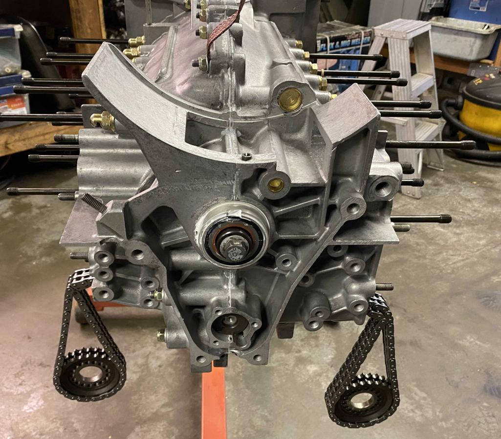
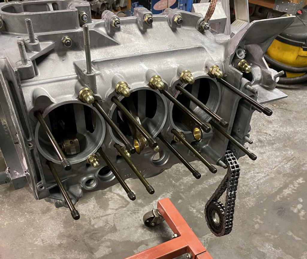
More engine build progress. Sealed up the case and installed the head studs.
   |
|
|
|
| Dion |
May 17 2024, 08:25 AM
Post
#343
|
|
RN Group: Members Posts: 2,920 Joined: 16-September 04 From: Audubon,PA Member No.: 2,766 Region Association: MidAtlantic Region |
The engine looks amazing. Beautiful work ! Like the rubber band mechanism, that gets it done. No flopping about. Look forward to more.
|
|
|
|
| Tom1394racing |
May 17 2024, 10:44 AM
Post
#344
|
|
Member Group: Members Posts: 493 Joined: 25-August 07 From: CT Member No.: 8,039 Region Association: North East States |
QUOTE(Dion @ May 17 2024, 10:25 AM)  The engine looks amazing. Beautiful work ! Like the rubber band mechanism, that gets it done. No flopping about. Look forward to more. Yeah...The rubber bands keep the rods from getting caught on the spigot bores and allow the engine to be rotated with no hang ups. |
|
|
|
| Tom1394racing |
May 17 2024, 02:28 PM
Post
#345
|
|
Member Group: Members Posts: 493 Joined: 25-August 07 From: CT Member No.: 8,039 Region Association: North East States |
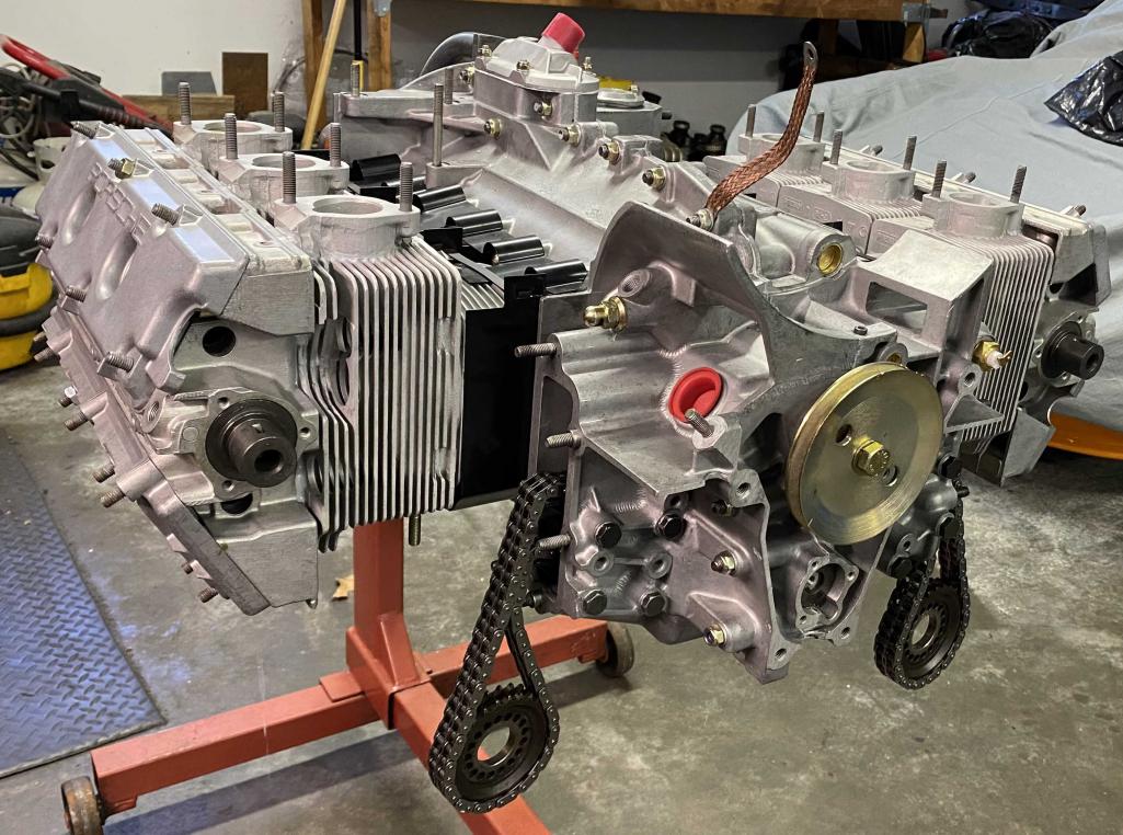
I installed the flywheel and crank pulley today. Being new to the 914 world, I am wondering where to make the ignition timing and TDC marks. I understand that the 914-6 had the timing marks on the flywheel in line with the crank pulley as there is no visual access to the crank pulley when the engine is installed. I am guessing that I should paint a fine white line on the edge of the flywheel at the case parting line when the same mark is lined up with the case parting line at the crank. One for TDC, one for my timing mark and one each at TDC for the other cylinders to enable setting the valve lash.
Am I on the right track? 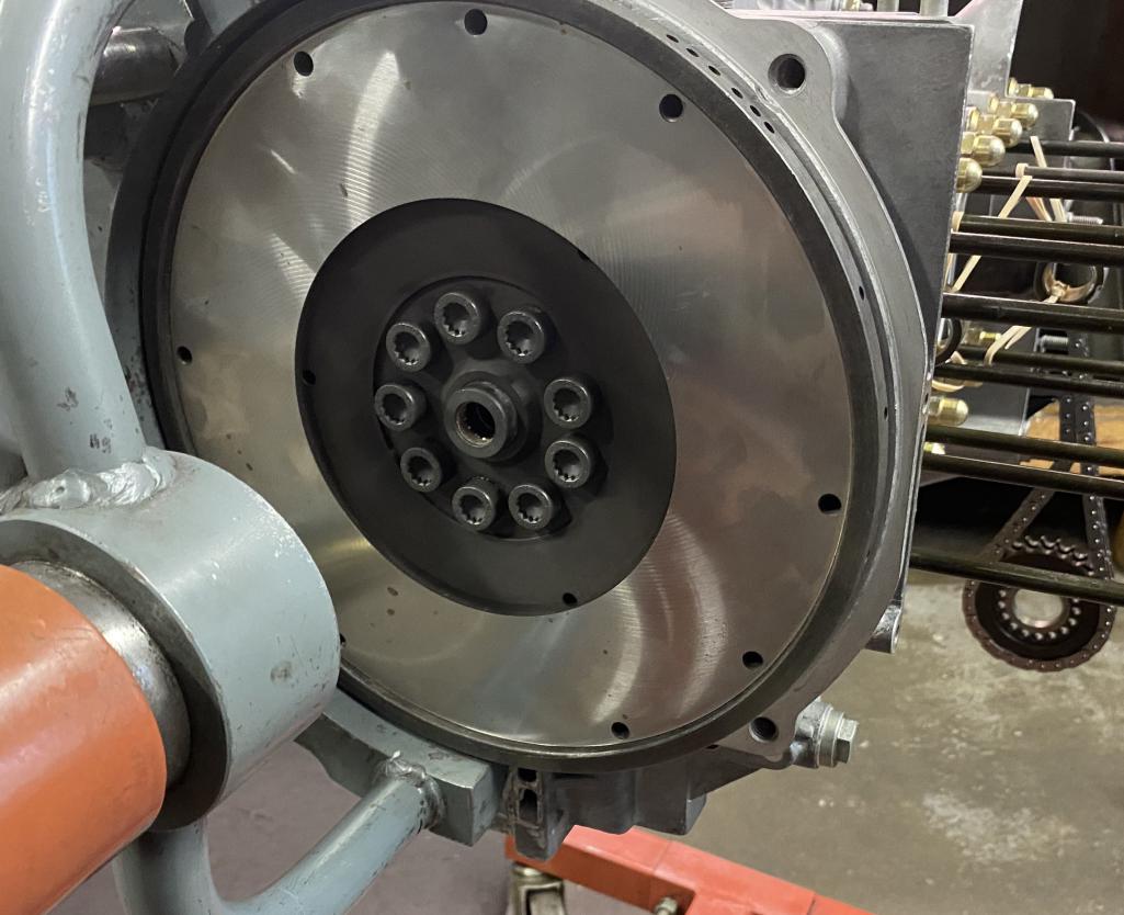 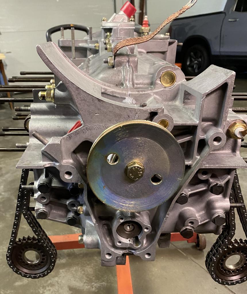 |
|
|
|
| Tom1394racing |
May 18 2024, 02:07 PM
Post
#346
|
|
Member Group: Members Posts: 493 Joined: 25-August 07 From: CT Member No.: 8,039 Region Association: North East States |
QUOTE(Tom1394racing @ May 17 2024, 04:28 PM) I installed the flywheel and crank pulley today. Being new to the 914 world, I am wondering where to make the ignition timing and TDC marks. I understand that the 914-6 had the timing marks on the flywheel in line with the crank pulley as there is no visual access to the crank pulley when the engine is installed. I am guessing that I should paint a fine white line on the edge of the flywheel at the case parting line when the same mark is lined up with the case parting line at the crank. One for TDC, one for my timing mark and one each at TDC for the other cylinders to enable setting the valve lash. Am I on the right track? After doing a little research on this timing topic, I concluded that I will mark the flywheel at TDC for each cylinder with a white paint marker and at my timing location with a yellow paint marker. I am hoping that the access panel in my firewall will allow me to see the crank pully and easily access the distributor, making the flywheel marking redundant. |
|
|
|
| mb911 |
May 18 2024, 04:58 PM
Post
#347
|
|
914 Guru Group: Members Posts: 7,698 Joined: 2-January 09 From: Burlington wi Member No.: 9,892 Region Association: Upper MidWest |
QUOTE(Tom1394racing @ May 18 2024, 12:07 PM) QUOTE(Tom1394racing @ May 17 2024, 04:28 PM) I installed the flywheel and crank pulley today. Being new to the 914 world, I am wondering where to make the ignition timing and TDC marks. I understand that the 914-6 had the timing marks on the flywheel in line with the crank pulley as there is no visual access to the crank pulley when the engine is installed. I am guessing that I should paint a fine white line on the edge of the flywheel at the case parting line when the same mark is lined up with the case parting line at the crank. One for TDC, one for my timing mark and one each at TDC for the other cylinders to enable setting the valve lash. Am I on the right track? After doing a little research on this timing topic, I concluded that I will mark the flywheel at TDC for each cylinder with a white paint marker and at my timing location with a yellow paint marker. I am hoping that the access panel in my firewall will allow me to see the crank pully and easily access the distributor, making the flywheel marking redundant. Ok dumb question as I have no personal experience with anything over a 2.7 engine in a 914-6 what pressure plate and transmission are you using with that flywheel? Every 6 conversion I have dealt with is a cup style flywheel and what you have would not work. |
|
|
|
| Tom1394racing |
May 19 2024, 08:23 AM
Post
#348
|
|
Member Group: Members Posts: 493 Joined: 25-August 07 From: CT Member No.: 8,039 Region Association: North East States |
Hi Ben
I am using a Kennedy Engineering 228 mm stage 2 clutch package. It allows conversion of the 915 9 bolt flywheel to the 901 type clutch and pressure plate. 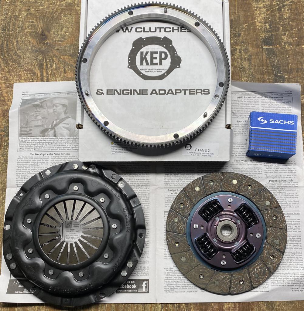 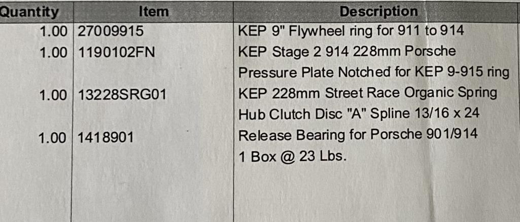 |
|
|
|
| rgalla9146 |
May 19 2024, 06:05 PM
Post
#349
|
|
Advanced Member Group: Members Posts: 4,896 Joined: 23-November 05 From: Paramus NJ Member No.: 5,176 Region Association: None |
QUOTE(Tom1394racing @ May 18 2024, 04:07 PM) QUOTE(Tom1394racing @ May 17 2024, 04:28 PM) I installed the flywheel and crank pulley today. Being new to the 914 world, I am wondering where to make the ignition timing and TDC marks. I understand that the 914-6 had the timing marks on the flywheel in line with the crank pulley as there is no visual access to the crank pulley when the engine is installed. I am guessing that I should paint a fine white line on the edge of the flywheel at the case parting line when the same mark is lined up with the case parting line at the crank. One for TDC, one for my timing mark and one each at TDC for the other cylinders to enable setting the valve lash. Am I on the right track? After doing a little research on this timing topic, I concluded that I will mark the flywheel at TDC for each cylinder with a white paint marker and at my timing location with a yellow paint marker. I am hoping that the access panel in my firewall will allow me to see the crank pully and easily access the distributor, making the flywheel marking redundant. Tom you're on the right track. Use the pulley marks as your guide on the flywheel. I don't know if you'll have proper flat surfaces to mark with those KEP parts. You're using a conventional dizzy ? If you adjust the timing through the access hole in the bulkhead be very careful ! Fans/fanbelts have no mercy. It's awkward but very convenient. |
|
|
|
| Tom1394racing |
May 20 2024, 09:10 AM
Post
#350
|
|
Member Group: Members Posts: 493 Joined: 25-August 07 From: CT Member No.: 8,039 Region Association: North East States |
Thanks Rory
I am using a JB Racing twin plug dizzy. I think if I mark both the flywheel and the KEP ring gear adapter, I will have something that will show up with my timing light. |
|
|
|
| Tom1394racing |
May 20 2024, 02:42 PM
Post
#351
|
|
Member Group: Members Posts: 493 Joined: 25-August 07 From: CT Member No.: 8,039 Region Association: North East States |
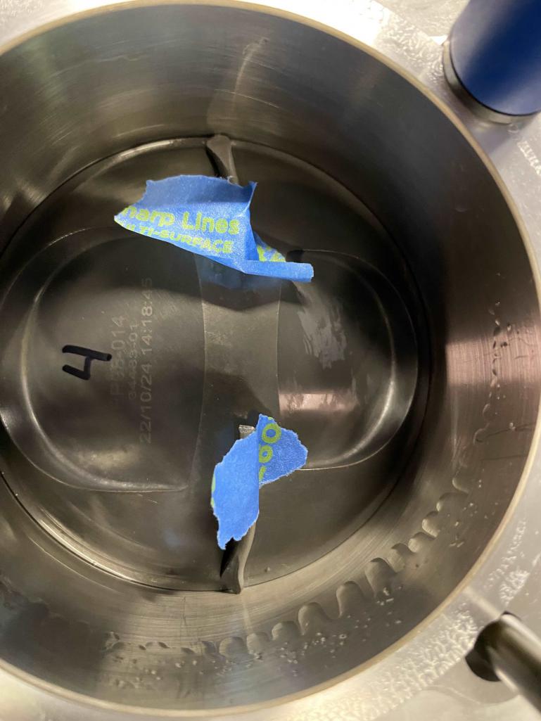
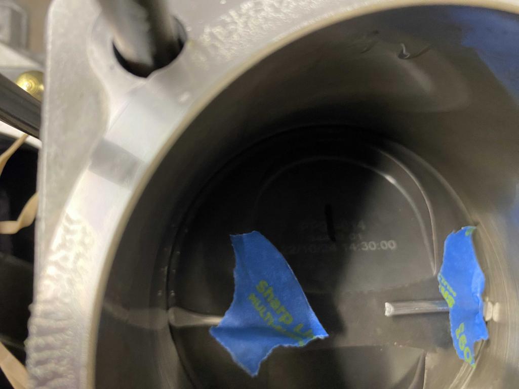
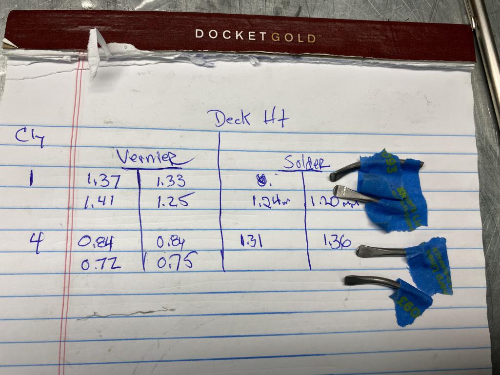
Today I did the deck height check using both the vernier at TDC and the solder method. I did the check on cylinders #1 and #4. Ollie's had supplied 0.5 mm base gaskets based on their resizing of the case. Using these gaskets, deck height as measured on the crushed solder came out at 1.2-1.3 mm. That along with my measured combustion chamber and piston dome volumes results in a 10.0:1 compression ratio. Right on target so I will move forward on the assembly.
   |
|
|
|
| Tom1394racing |
May 21 2024, 05:27 PM
Post
#352
|
|
Member Group: Members Posts: 493 Joined: 25-August 07 From: CT Member No.: 8,039 Region Association: North East States |
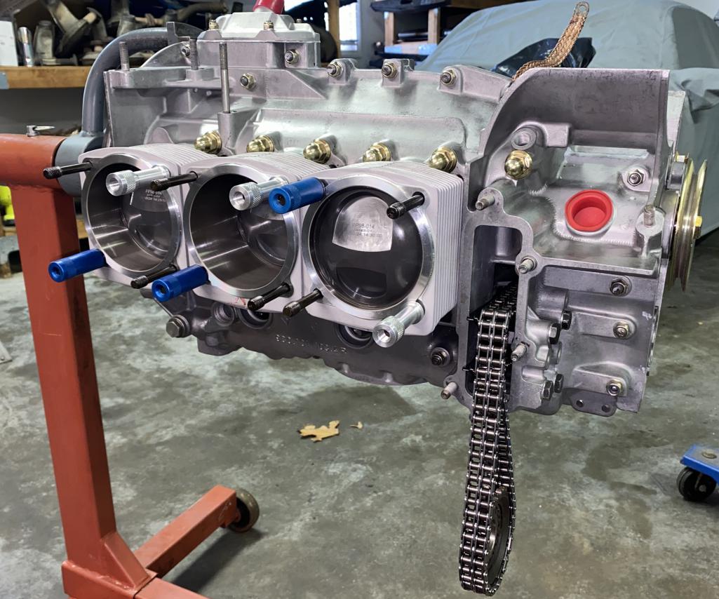
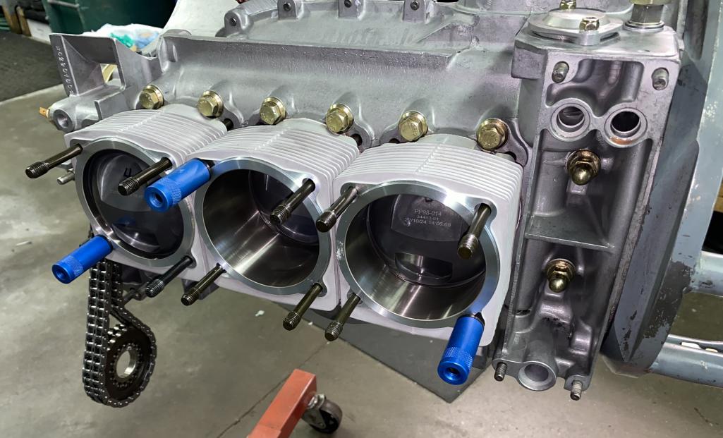
Pistons and cylinders went in today.
  |
|
|
|
| Tom1394racing |
May 28 2024, 01:23 PM
Post
#353
|
|
Member Group: Members Posts: 493 Joined: 25-August 07 From: CT Member No.: 8,039 Region Association: North East States |
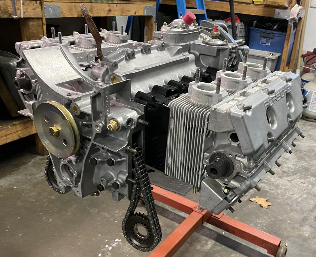
Continuing to move forward on the engine build. Heads and cam towers are now installed, and the cams test fitted.
  |
|
|
|
| mepstein |
May 28 2024, 02:46 PM
Post
#354
|
|
914-6 GT in waiting Group: Members Posts: 20,289 Joined: 19-September 09 From: Landenberg, PA/Wilmington, DE Member No.: 10,825 Region Association: MidAtlantic Region |
Looks great.
|
 |
|
| Tom1394racing |
May 28 2024, 05:53 PM
Post
#355
|
|
Member Group: Members Posts: 493 Joined: 25-August 07 From: CT Member No.: 8,039 Region Association: North East States |
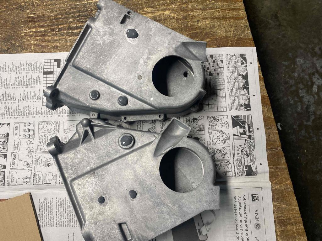
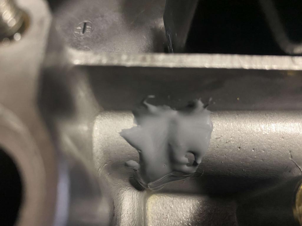
I applied JB Weld to seal the chain rail and tensioner posts on the backside of the chain boxes. I also used the JB Weld to seal the case oil line webbing on the RHS of the case behind the oil cooler.
  |
|
|
|
| Tom1394racing |
Jun 1 2024, 04:22 PM
Post
#356
|
|
Member Group: Members Posts: 493 Joined: 25-August 07 From: CT Member No.: 8,039 Region Association: North East States |
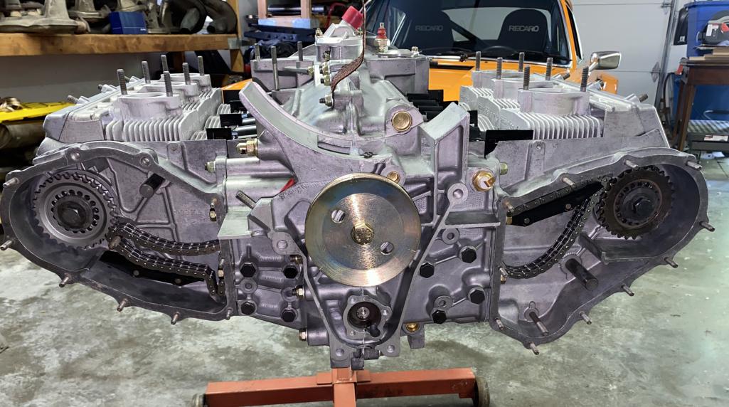
Ready for sprocket alignment check.
 |
|
|
|
| Tom1394racing |
Jun 5 2024, 10:40 AM
Post
#357
|
|
Member Group: Members Posts: 493 Joined: 25-August 07 From: CT Member No.: 8,039 Region Association: North East States |
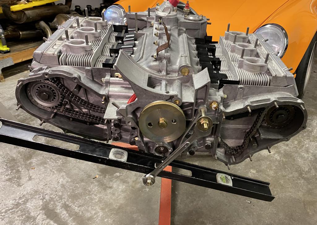
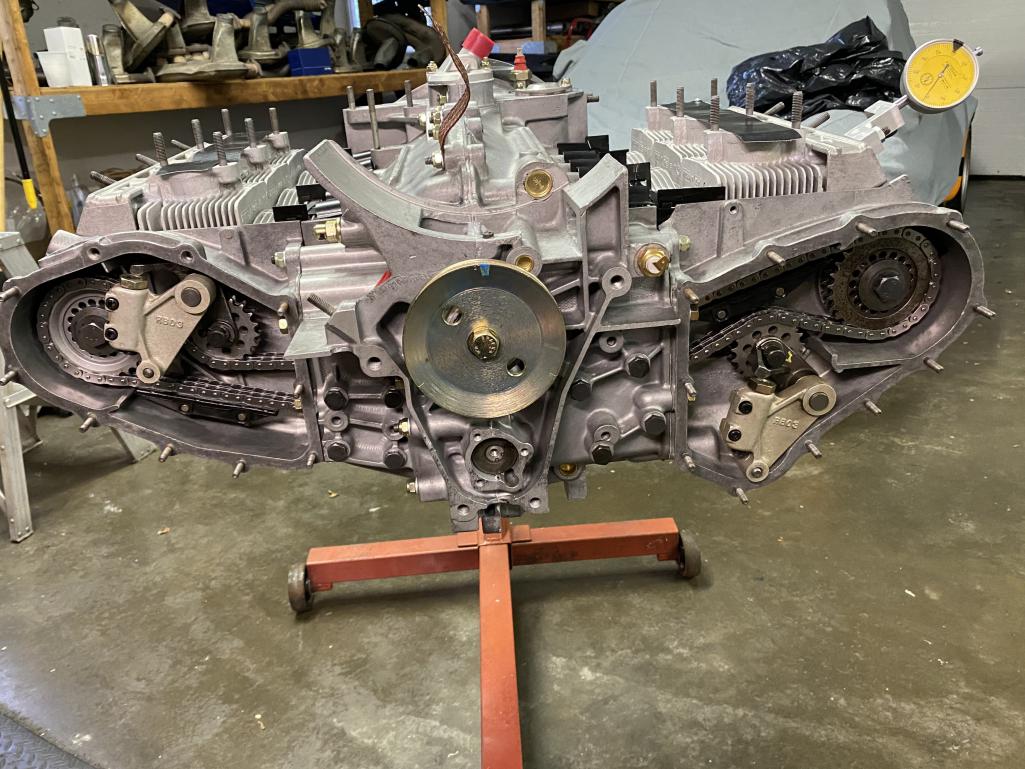
Here is my homemade setup for the sprocket alignment. Works well. Very accurate and repeatable. I ended up with (3) shims per side. Next up will be the cam timing.
 |
|
|
|
| Tom1394racing |
Jun 6 2024, 07:26 AM
Post
#358
|
|
Member Group: Members Posts: 493 Joined: 25-August 07 From: CT Member No.: 8,039 Region Association: North East States |
I did the cam timing yesterday. DC-60 cams with a spec of 4.8-5.2 mm at overlap. I set them at 5.25 mm.
 |
|
|
|
| gereed75 |
Jun 6 2024, 07:49 AM
Post
#359
|
|
Senior Member Group: Members Posts: 1,408 Joined: 19-March 13 From: Pittsburgh PA Member No.: 15,674 Region Association: North East States |
That is some sweet work right there. Wow
|
|
|
|
| mb911 |
Jun 6 2024, 02:15 PM
Post
#360
|
|
914 Guru Group: Members Posts: 7,698 Joined: 2-January 09 From: Burlington wi Member No.: 9,892 Region Association: Upper MidWest |
Looks great
|
|
|
|
|
2 User(s) are reading this topic (2 Guests and 0 Anonymous Users)
0 Members:

|
Lo-Fi Version | Time is now: 14th December 2025 - 11:43 AM |
Invision Power Board
v9.1.4 © 2025 IPS, Inc.