|
|
|
Porsche, and the Porsche crest are registered trademarks of Dr. Ing. h.c. F. Porsche AG.
This site is not affiliated with Porsche in any way. Its only purpose is to provide an online forum for car enthusiasts. All other trademarks are property of their respective owners. |
|
|


| ottox914 |
 Dec 24 2006, 01:44 PM Dec 24 2006, 01:44 PM
Post
#61
|
|
The glory that once was.  Group: Members Posts: 1,302 Joined: 15-December 03 From: Mahtomedi, MN Member No.: 1,438 Region Association: Upper MidWest |
Just a little teaser on this winters project. Last winter I dug into this little update:
http://www.914world.com/bbs2/index.php?sho...c=53733&hl= This winter will be phase 2. This photo will show some of the goodies under the tree, which will soon be under/on the car. The WRX intercooler has one round inlet on the back, and 2 smaller oval outlets under the opposite end tank. These will each exit and attach to some CB performance turbo "hats" for the ITB's that have 2" tubes welded to them. Some silicone elbows, and we're good. The intercooler will mount on braces running across the engine bay to support the intercooler as close to the GT lid as possible. I'll see how it goes, and probably do some yarn tuft testing to see about airflow in and around that lid, but I could always use the SDS computer to switch on either a puller or pusher fan below the intercooler based on boost, if needed. The turbo will mount on a custom flange/adaptor to be built to connect the turbo to the collector of the Kerry Hunter exhaust system. The turbo is a small Garrett VNT. The compressor map looks like a good match for this motor. I'm expecting the VNT turbo to give good low rpm thorttle response. Starting out at 5-6 psi, I'd be happy to see 10 when I'm done, but will tune to run safely on 93 pump gas and see where we end up. Off the back of the transmission, where the factory exhaust hanger mounted, I'll mount a similar hanger to support the turbo and exhaust system. A Tildon differential pump will return the oil to a willing valve cover. Oil will be taken from a "T" at the pressure sending unit on the case. There is a blow off valve to be added to the intercooler, and a mocal thermostat/sandwitch plate adaptor for the oil cooler, which has a thermostat controlled fan. I'll be adding an ignition switched relay for power to the fan and scavenge pump, so both will have power when the key is on. The pump will run continously, the fan when the thermo switch tells it to. Add some pressure side stainless or aluminum tubing from the turbo, thru the back engine tin, into the round inlet on the intercooler and we're done. Except for another trip to the LSE dyno, for some additional tuning. I'll keep posting as progress would warrent. Attached image(s) 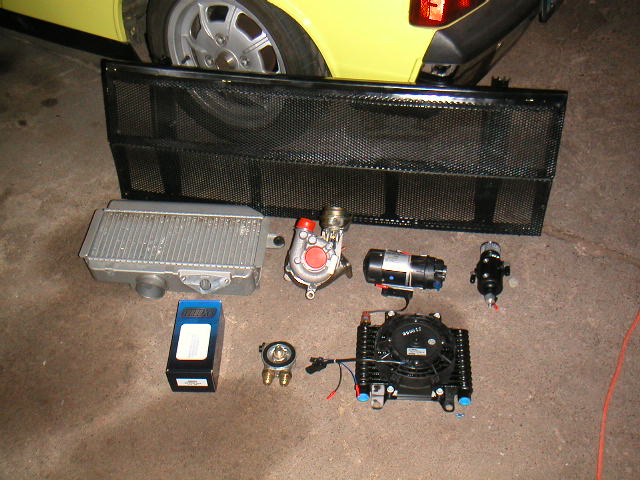
|
   |

 
|
Posts in this topic
 ottox914 Project Turbo 914 begins... Dec 24 2006, 01:44 PM
 ChrisNPDrider Sweet! I like the the header collector mount/i... Dec 25 2006, 04:23 PM
 Crazyhippy
Sweet! I like the the header collector mount/... Jan 8 2007, 07:36 PM ottox914 Now that the holidays have come and gone, and my r... Jan 8 2007, 02:19 PM Mueller
Now that the holidays have come and gone, and my ... Jan 8 2007, 04:24 PM Mark Henry Very cool David. We're thinking along the same... Jan 8 2007, 03:20 PM GS Guy Cool project David!
You do know the two openi... Jan 8 2007, 04:23 PM ottox914 Here come some pics- being only slightly more comp... Jan 8 2007, 06:45 PM ottox914 Here's a couple of the GT lid with the goodies... Jan 8 2007, 06:47 PM ottox914 Mark Henry- Why DTM, besides your selling Jakes pa... Jan 8 2007, 10:54 PM Mark Henry
Mark Henry- Why DTM, besides your selling Jakes p... Jan 10 2007, 08:23 AM Crazyhippy That is a perfectly fine description. Looks like f... Jan 8 2007, 11:00 PM ottox914 Not alot of turbo specific progress today, but som... Jan 10 2007, 10:53 PM ottox914 After removing the old filter and draining the oil... Jan 10 2007, 10:58 PM ottox914 1-16-07 updates- got the oil cooler installed- sor... Jan 13 2007, 08:36 PM ottox914 Mounting the cooler. The threaded rod went thru t... Jan 13 2007, 08:38 PM Andyrew those are really long threads...
Get 1in long one... Jan 13 2007, 09:29 PM Crazyhippy have to space the cooler away from the floor for a... Jan 14 2007, 12:52 AM ottox914
have to space the cooler away from the floor for ... Jan 14 2007, 07:44 AM Dave-O Looks good Dave! What kind of stock did you g... Jan 14 2007, 10:20 AM Andyrew Oh, I thought that you were going to cut the trunk... Jan 14 2007, 11:43 AM ottox914 Lee and Dave-o came over for the day. We played s... Jan 15 2007, 09:24 PM Andyrew post it on youtube, and link here. Jan 16 2007, 12:02 AM ottox914 Some progress from today and tonight. re-did the ... Jan 26 2007, 09:35 PM ottox914 Also got the fancy intercooler mounts, made by our... Jan 26 2007, 09:42 PM Andyrew Thats lookin much betta!!!
Everything... Jan 26 2007, 11:44 PM Dave-O Looks good Dave! I can't wait to see the ... Jan 27 2007, 11:39 AM Brando Do like on 930s and force most of the engine cooli... Jan 27 2007, 03:23 PM ottox914 Finally some progress. With work, Christmas, New Y... Apr 1 2007, 07:18 PM ottox914 Here are some shots of the back of the intercooler... Apr 1 2007, 07:21 PM ottox914 Here are the connections for the right side ITB. ... Apr 1 2007, 07:24 PM ottox914 Plenty of work yet to be done. Need to mount and ... Apr 1 2007, 07:28 PM iamchappy Looking good, it looks like you've got it well... Apr 1 2007, 07:41 PM Dave-O I like that plumbing a lot! I wish I either l... Apr 1 2007, 07:55 PM JPB Nice work and looks killer clean mister :thumbsup: Apr 1 2007, 08:14 PM pankopp waiting for an update! .... show us.... please... Apr 6 2007, 12:22 AM ottox914 I've had way to much of my real job to deal wi... Apr 6 2007, 07:29 AM iamchappy I've been looking into an temp adjustable fan ... Apr 6 2007, 09:08 AM ottox914 The SDS on my car will do a single ground switched... Apr 6 2007, 12:24 PM iamchappy The probe like you mention i found was the Davis C... Apr 6 2007, 01:09 PM ottox914 More updates but still not done. Progress is movi... Apr 10 2007, 07:51 PM ottox914 Next photos are of the pipeing from the intercoole... Apr 10 2007, 07:54 PM Crazyhippy Keeping the intercooler fan on is a good idea. The... Apr 10 2007, 08:30 PM Krieger914 Get it to work really well, then paint/detail it. ... Apr 10 2007, 09:43 PM Tobra You could put some misters over the IC and hook it... Apr 17 2007, 12:54 AM ottox914 Good things come to those who wait... well, I... Apr 18 2007, 08:46 AM Scott-thundercat any updates? May 8 2007, 11:39 PM Nor.Cal.914 How's your progress coming along with this? I... Jun 10 2007, 04:02 AM Scott-thundercat any new info? Jul 8 2007, 09:01 PM ottox914 Really nothing much new to report. My local mega-... Jul 8 2007, 10:40 PM ottox914 Finally some more progress!!! Got big... Sep 1 2007, 10:48 PM ottox914 I also revised the lines to the puke tank, running... Sep 1 2007, 10:54 PM ottox914 Now for some good stuff. Got all the piping rough... Sep 1 2007, 11:04 PM ottox914 Thats pretty much for the updates for now. Last w... Sep 1 2007, 11:10 PM marks914 Hey David,
Did you get a chance to try out that 2n... Sep 2 2007, 10:11 AM JPB Everyone knows you can't turbo a T4, should of... Sep 2 2007, 07:19 PM ottox914 Mark, only had saturday to get to the car, family ... Sep 3 2007, 09:34 PM 914-gt Hi David, thats a nice set up!
Does anyone kn... Sep 3 2007, 11:46 PM ottox914 All kinds of updates: her is a link to the "b... Sep 13 2007, 09:45 PM ottox914 ... now on to the good stuff. All this took place... Sep 13 2007, 09:55 PM ottox914 Moving on to other work, I re-plumbed the puke tan... Sep 13 2007, 10:00 PM ottox914 Final cuts of tubing, and the masked welder in act... Sep 13 2007, 10:09 PM ottox914 Right and left sides completed! Sep 13 2007, 10:13 PM ottox914 Intercooler mounted and connected to the round to ... Sep 13 2007, 10:23 PM ottox914 On to the good stuff. Think we'll have to tri... Sep 13 2007, 10:30 PM ottox914 Some close ups of the flanges we had to make, and ... Sep 13 2007, 10:33 PM ottox914 Last installment for tonight- I took and hosed dow... Sep 13 2007, 10:37 PM ottox914 I just re-read the thread and see that I 2x posted... Sep 13 2007, 10:43 PM ottox914 A few more updates- over the weekend, I swapped ou... Sep 26 2007, 08:40 AM ottox914 I also got the tildon differential pump (now scave... Sep 26 2007, 08:46 AM ottox914 Here are some pics of the pump on the car. I foun... Sep 26 2007, 08:50 AM ottox914 Couldn't fit all the pics on that last post, h... Sep 26 2007, 08:58 AM Brian Mifsud Dave,
Is your turbo oil circuit seperate from the... Sep 26 2007, 11:32 AM iamchappy It would be best to have a small sump under the tu... Sep 26 2007, 12:36 PM ottox914 Brian- the engine oil is pressurized, and I am tap... Sep 26 2007, 02:24 PM iamchappy I had problems scavenging fast enough with the Til... Sep 26 2007, 06:28 PM ottox914 chappy- pm sent. Sep 27 2007, 10:39 AM Aaron Cox looks great!
so how do you put oil in it? Sep 27 2007, 11:02 AM ottox914 More updates- I'm so close now I can feel the ... Sep 27 2007, 10:27 PM ottox914 Here's a couple money shots for you- turbo, ai... Sep 27 2007, 10:30 PM ottox914 One more of the install. I plan to build a 1/2 ro... Sep 27 2007, 10:32 PM ottox914 A few more install shots, working on the oil lines... Sep 27 2007, 10:40 PM ChrisNPDrider Beautiful! :beer2:
Minimal cutting, fits gre... Sep 27 2007, 11:00 PM ottox914 Turbo update. Nothing but hurt. Will post more p... Oct 4 2007, 09:50 PM GS Guy That stinks, I'd check the turbo over really w... Oct 5 2007, 06:51 AM arvcube oil out the exhaust usually means that the seals i... Nov 30 2007, 10:26 PM ottox914 TURBO 914 LIVES!!!
Round 2 with a wr... Jan 4 2008, 10:48 PM Sleepin :headbanger: That rocks! You are going to have... Jan 4 2008, 11:57 PM GS Guy That's great news David! :Qarl:
Looking... Jan 5 2008, 07:52 AM jimkelly i am on a hunger strike until we get some video : ... Jan 5 2008, 08:23 AM nsr-jamie Wow, this is a cool post. I just noticed it now, I... Jan 5 2008, 08:23 AM ottox914 This may take a while, so get comfy.
Recap: Eve... Jan 6 2008, 08:06 PM iamchappy David, it's nice to see you are using the oil ... Jan 6 2008, 08:20 PM ottox914 More pics- here are some of the oiling system, the... Jan 6 2008, 08:21 PM ottox914 Where does the air go after it enters the turbo? H... Jan 6 2008, 08:31 PM ottox914 Remaining to be done?
Lots.
Add the puller fa... Jan 6 2008, 08:40 PM iamchappy I agree that oil can is to low, ditch it. The reas... Jan 6 2008, 09:01 PM Sleepin Dave, All looks good. I would say your oil return... Jan 6 2008, 10:48 PM nein14 :popcorn: Jan 7 2008, 04:58 PM niterydr :DRUNK: :Qarl:
This will be fun to tune :) Jan 8 2008, 10:15 PM
Crazyhippy
Sweet! I like the the header collector mount/... Jan 8 2007, 07:36 PM ottox914 Now that the holidays have come and gone, and my r... Jan 8 2007, 02:19 PM Mueller
Now that the holidays have come and gone, and my ... Jan 8 2007, 04:24 PM Mark Henry Very cool David. We're thinking along the same... Jan 8 2007, 03:20 PM GS Guy Cool project David!
You do know the two openi... Jan 8 2007, 04:23 PM ottox914 Here come some pics- being only slightly more comp... Jan 8 2007, 06:45 PM ottox914 Here's a couple of the GT lid with the goodies... Jan 8 2007, 06:47 PM ottox914 Mark Henry- Why DTM, besides your selling Jakes pa... Jan 8 2007, 10:54 PM Mark Henry
Mark Henry- Why DTM, besides your selling Jakes p... Jan 10 2007, 08:23 AM Crazyhippy That is a perfectly fine description. Looks like f... Jan 8 2007, 11:00 PM ottox914 Not alot of turbo specific progress today, but som... Jan 10 2007, 10:53 PM ottox914 After removing the old filter and draining the oil... Jan 10 2007, 10:58 PM ottox914 1-16-07 updates- got the oil cooler installed- sor... Jan 13 2007, 08:36 PM ottox914 Mounting the cooler. The threaded rod went thru t... Jan 13 2007, 08:38 PM Andyrew those are really long threads...
Get 1in long one... Jan 13 2007, 09:29 PM Crazyhippy have to space the cooler away from the floor for a... Jan 14 2007, 12:52 AM ottox914
have to space the cooler away from the floor for ... Jan 14 2007, 07:44 AM Dave-O Looks good Dave! What kind of stock did you g... Jan 14 2007, 10:20 AM Andyrew Oh, I thought that you were going to cut the trunk... Jan 14 2007, 11:43 AM ottox914 Lee and Dave-o came over for the day. We played s... Jan 15 2007, 09:24 PM Andyrew post it on youtube, and link here. Jan 16 2007, 12:02 AM ottox914 Some progress from today and tonight. re-did the ... Jan 26 2007, 09:35 PM ottox914 Also got the fancy intercooler mounts, made by our... Jan 26 2007, 09:42 PM Andyrew Thats lookin much betta!!!
Everything... Jan 26 2007, 11:44 PM Dave-O Looks good Dave! I can't wait to see the ... Jan 27 2007, 11:39 AM Brando Do like on 930s and force most of the engine cooli... Jan 27 2007, 03:23 PM ottox914 Finally some progress. With work, Christmas, New Y... Apr 1 2007, 07:18 PM ottox914 Here are some shots of the back of the intercooler... Apr 1 2007, 07:21 PM ottox914 Here are the connections for the right side ITB. ... Apr 1 2007, 07:24 PM ottox914 Plenty of work yet to be done. Need to mount and ... Apr 1 2007, 07:28 PM iamchappy Looking good, it looks like you've got it well... Apr 1 2007, 07:41 PM Dave-O I like that plumbing a lot! I wish I either l... Apr 1 2007, 07:55 PM JPB Nice work and looks killer clean mister :thumbsup: Apr 1 2007, 08:14 PM pankopp waiting for an update! .... show us.... please... Apr 6 2007, 12:22 AM ottox914 I've had way to much of my real job to deal wi... Apr 6 2007, 07:29 AM iamchappy I've been looking into an temp adjustable fan ... Apr 6 2007, 09:08 AM ottox914 The SDS on my car will do a single ground switched... Apr 6 2007, 12:24 PM iamchappy The probe like you mention i found was the Davis C... Apr 6 2007, 01:09 PM ottox914 More updates but still not done. Progress is movi... Apr 10 2007, 07:51 PM ottox914 Next photos are of the pipeing from the intercoole... Apr 10 2007, 07:54 PM Crazyhippy Keeping the intercooler fan on is a good idea. The... Apr 10 2007, 08:30 PM Krieger914 Get it to work really well, then paint/detail it. ... Apr 10 2007, 09:43 PM Tobra You could put some misters over the IC and hook it... Apr 17 2007, 12:54 AM ottox914 Good things come to those who wait... well, I... Apr 18 2007, 08:46 AM Scott-thundercat any updates? May 8 2007, 11:39 PM Nor.Cal.914 How's your progress coming along with this? I... Jun 10 2007, 04:02 AM Scott-thundercat any new info? Jul 8 2007, 09:01 PM ottox914 Really nothing much new to report. My local mega-... Jul 8 2007, 10:40 PM ottox914 Finally some more progress!!! Got big... Sep 1 2007, 10:48 PM ottox914 I also revised the lines to the puke tank, running... Sep 1 2007, 10:54 PM ottox914 Now for some good stuff. Got all the piping rough... Sep 1 2007, 11:04 PM ottox914 Thats pretty much for the updates for now. Last w... Sep 1 2007, 11:10 PM marks914 Hey David,
Did you get a chance to try out that 2n... Sep 2 2007, 10:11 AM JPB Everyone knows you can't turbo a T4, should of... Sep 2 2007, 07:19 PM ottox914 Mark, only had saturday to get to the car, family ... Sep 3 2007, 09:34 PM 914-gt Hi David, thats a nice set up!
Does anyone kn... Sep 3 2007, 11:46 PM ottox914 All kinds of updates: her is a link to the "b... Sep 13 2007, 09:45 PM ottox914 ... now on to the good stuff. All this took place... Sep 13 2007, 09:55 PM ottox914 Moving on to other work, I re-plumbed the puke tan... Sep 13 2007, 10:00 PM ottox914 Final cuts of tubing, and the masked welder in act... Sep 13 2007, 10:09 PM ottox914 Right and left sides completed! Sep 13 2007, 10:13 PM ottox914 Intercooler mounted and connected to the round to ... Sep 13 2007, 10:23 PM ottox914 On to the good stuff. Think we'll have to tri... Sep 13 2007, 10:30 PM ottox914 Some close ups of the flanges we had to make, and ... Sep 13 2007, 10:33 PM ottox914 Last installment for tonight- I took and hosed dow... Sep 13 2007, 10:37 PM ottox914 I just re-read the thread and see that I 2x posted... Sep 13 2007, 10:43 PM ottox914 A few more updates- over the weekend, I swapped ou... Sep 26 2007, 08:40 AM ottox914 I also got the tildon differential pump (now scave... Sep 26 2007, 08:46 AM ottox914 Here are some pics of the pump on the car. I foun... Sep 26 2007, 08:50 AM ottox914 Couldn't fit all the pics on that last post, h... Sep 26 2007, 08:58 AM Brian Mifsud Dave,
Is your turbo oil circuit seperate from the... Sep 26 2007, 11:32 AM iamchappy It would be best to have a small sump under the tu... Sep 26 2007, 12:36 PM ottox914 Brian- the engine oil is pressurized, and I am tap... Sep 26 2007, 02:24 PM iamchappy I had problems scavenging fast enough with the Til... Sep 26 2007, 06:28 PM ottox914 chappy- pm sent. Sep 27 2007, 10:39 AM Aaron Cox looks great!
so how do you put oil in it? Sep 27 2007, 11:02 AM ottox914 More updates- I'm so close now I can feel the ... Sep 27 2007, 10:27 PM ottox914 Here's a couple money shots for you- turbo, ai... Sep 27 2007, 10:30 PM ottox914 One more of the install. I plan to build a 1/2 ro... Sep 27 2007, 10:32 PM ottox914 A few more install shots, working on the oil lines... Sep 27 2007, 10:40 PM ChrisNPDrider Beautiful! :beer2:
Minimal cutting, fits gre... Sep 27 2007, 11:00 PM ottox914 Turbo update. Nothing but hurt. Will post more p... Oct 4 2007, 09:50 PM GS Guy That stinks, I'd check the turbo over really w... Oct 5 2007, 06:51 AM arvcube oil out the exhaust usually means that the seals i... Nov 30 2007, 10:26 PM ottox914 TURBO 914 LIVES!!!
Round 2 with a wr... Jan 4 2008, 10:48 PM Sleepin :headbanger: That rocks! You are going to have... Jan 4 2008, 11:57 PM GS Guy That's great news David! :Qarl:
Looking... Jan 5 2008, 07:52 AM jimkelly i am on a hunger strike until we get some video : ... Jan 5 2008, 08:23 AM nsr-jamie Wow, this is a cool post. I just noticed it now, I... Jan 5 2008, 08:23 AM ottox914 This may take a while, so get comfy.
Recap: Eve... Jan 6 2008, 08:06 PM iamchappy David, it's nice to see you are using the oil ... Jan 6 2008, 08:20 PM ottox914 More pics- here are some of the oiling system, the... Jan 6 2008, 08:21 PM ottox914 Where does the air go after it enters the turbo? H... Jan 6 2008, 08:31 PM ottox914 Remaining to be done?
Lots.
Add the puller fa... Jan 6 2008, 08:40 PM iamchappy I agree that oil can is to low, ditch it. The reas... Jan 6 2008, 09:01 PM Sleepin Dave, All looks good. I would say your oil return... Jan 6 2008, 10:48 PM nein14 :popcorn: Jan 7 2008, 04:58 PM niterydr :DRUNK: :Qarl:
This will be fun to tune :) Jan 8 2008, 10:15 PM  |
1 User(s) are reading this topic (1 Guests and 0 Anonymous Users)
0 Members:

|
Lo-Fi Version | Time is now: 9th June 2026 - 01:23 AM |
Invision Power Board
v9.1.4 © 2026 IPS, Inc.