|
|
|
Porsche, and the Porsche crest are registered trademarks of Dr. Ing. h.c. F. Porsche AG.
This site is not affiliated with Porsche in any way. Its only purpose is to provide an online forum for car enthusiasts. All other trademarks are property of their respective owners. |
|
|

  |

| 3d914 |
 Oct 11 2013, 08:35 PM Oct 11 2013, 08:35 PM
Post
#301
|
|
Senior Member  Group: Members Posts: 1,275 Joined: 24-September 03 From: Benson, AZ Member No.: 1,191 Region Association: Southwest Region |
Had a couple of hours today to work on the left side lower transition piece. Hope to get it tacked in tomorrow.
 |
   |

 
|
| 3d914 |
Oct 19 2013, 04:04 PM
Post
#302
|
|
Senior Member Group: Members Posts: 1,275 Joined: 24-September 03 From: Benson, AZ Member No.: 1,191 Region Association: Southwest Region |
Got some .030 wire - which improved the butt welds on the right side, but still can't fill small gaps without blowing thru. Gonna go on the hunt for a used welder, but need to narrow what I'm looking for first.
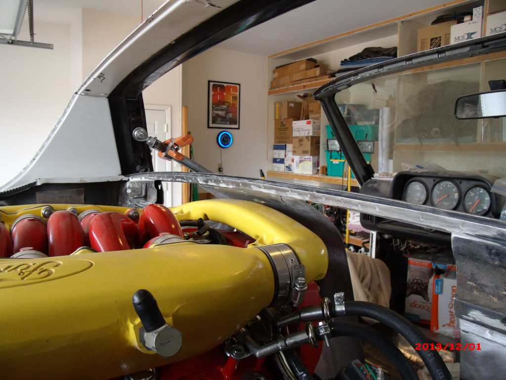
 Also got some time today to do another test fit. With the front firewall cutout I was hoping I could get the intake on, but it looks like I have some more trimming to do on the rear firewall. You can see on the left side how the valve cover is going to interfere with the angled portion of the rear firewall. And the motor is positioned 3/4" too far forward in this pic. 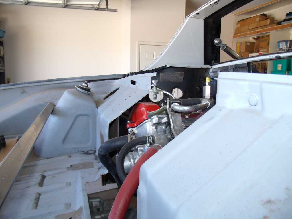 Looking real good on the right side. 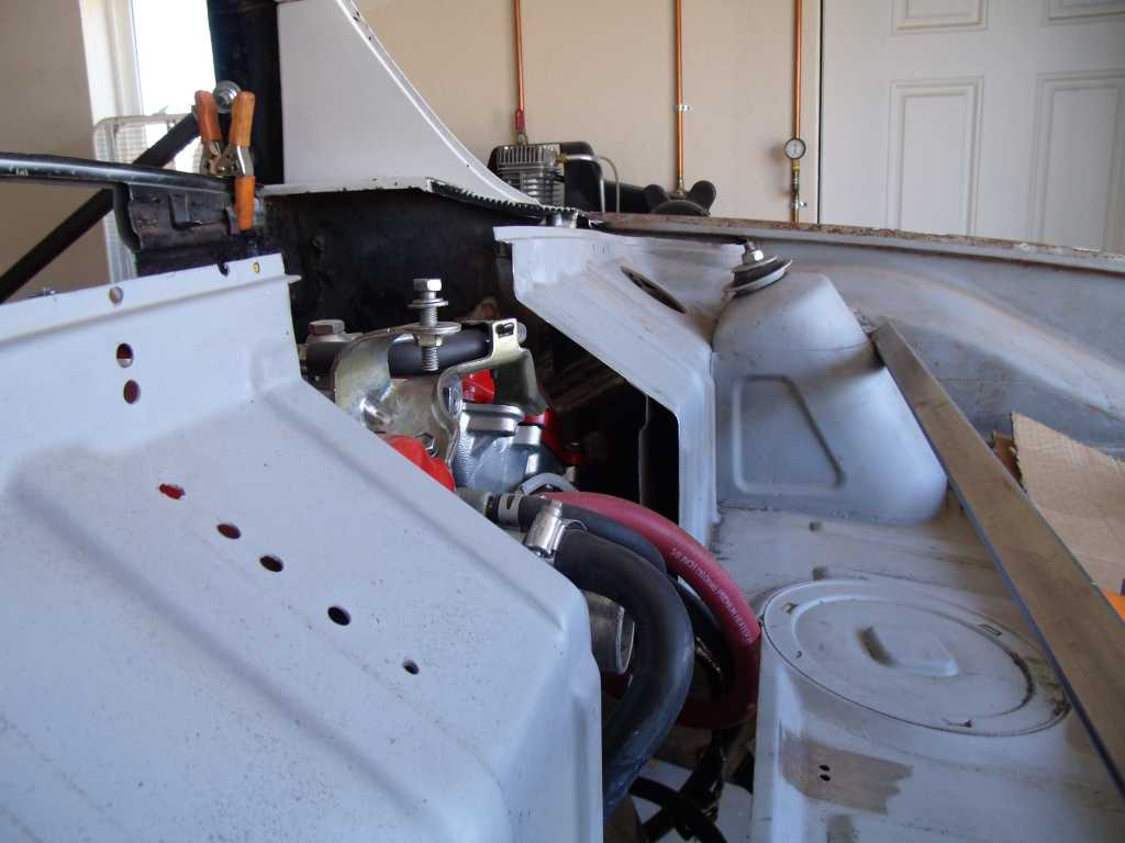 You can tell from the output shaft flanges that motor needs to come back almost an inch. 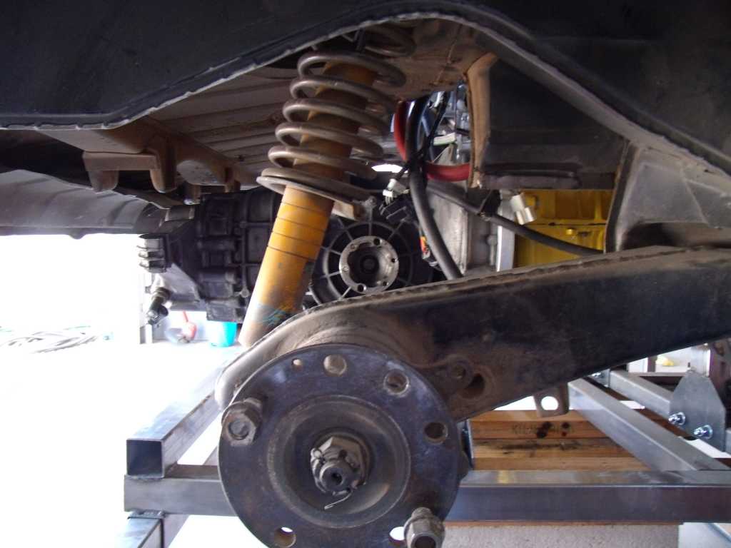 Also getting real close to the power steering pulley - need that extra 3/4" or so. 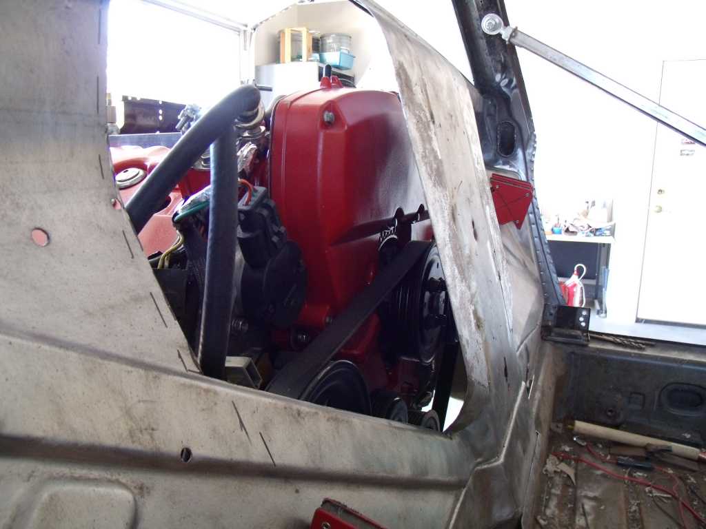 |
|
|
|
| 3d914 |
Nov 10 2013, 05:57 PM
Post
#303
|
|
Senior Member Group: Members Posts: 1,275 Joined: 24-September 03 From: Benson, AZ Member No.: 1,191 Region Association: Southwest Region |
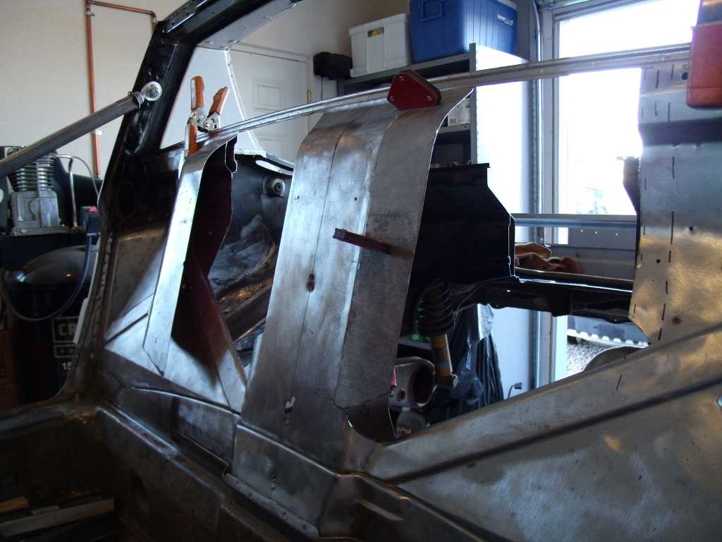
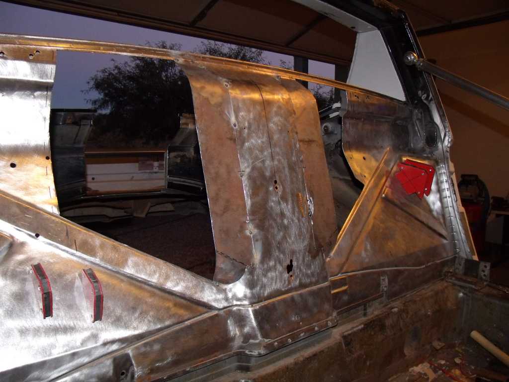
Got some time in this weekend to continue shaping the main firewall pieces. Feel like I'm chasing my tail on this left one. Every time I get one part of it to fit - something changes elsewhere. I've been using large magnets to hold the piece in place while I make adjustments, but they don't seem to hold very well. So I spent some time modifying my sheet metal clamps - used when butt-welding - so they will fit better and leave a smaller gap. I'm going to use three or four of them to hold the piece in place while I mark & make final adjustments.
Also spent time cleaning up the back side of the main firewall. Got the glue and paint off the upper firewall, except for the smaller sections in the corners. This will make the remaining cutting & welding work easier. Looks pertty - wish I could keep it this way. 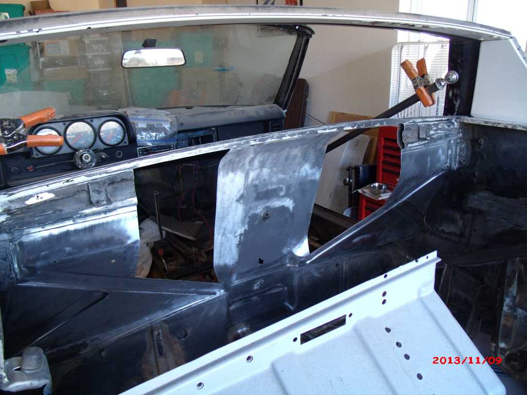 |
|
|
|
| 3d914 |
Nov 17 2013, 01:25 PM
Post
#304
|
|
Senior Member Group: Members Posts: 1,275 Joined: 24-September 03 From: Benson, AZ Member No.: 1,191 Region Association: Southwest Region |
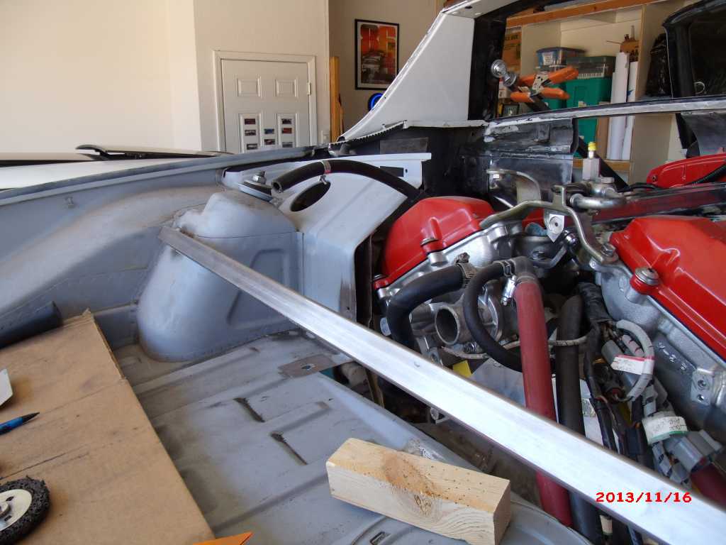
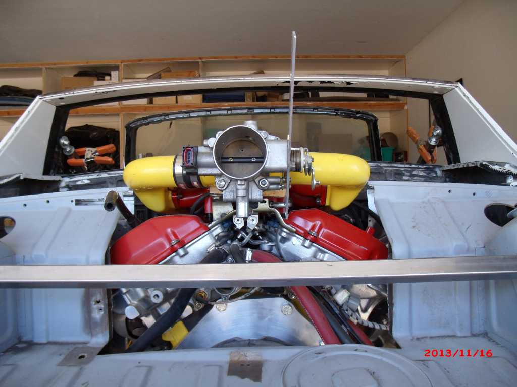
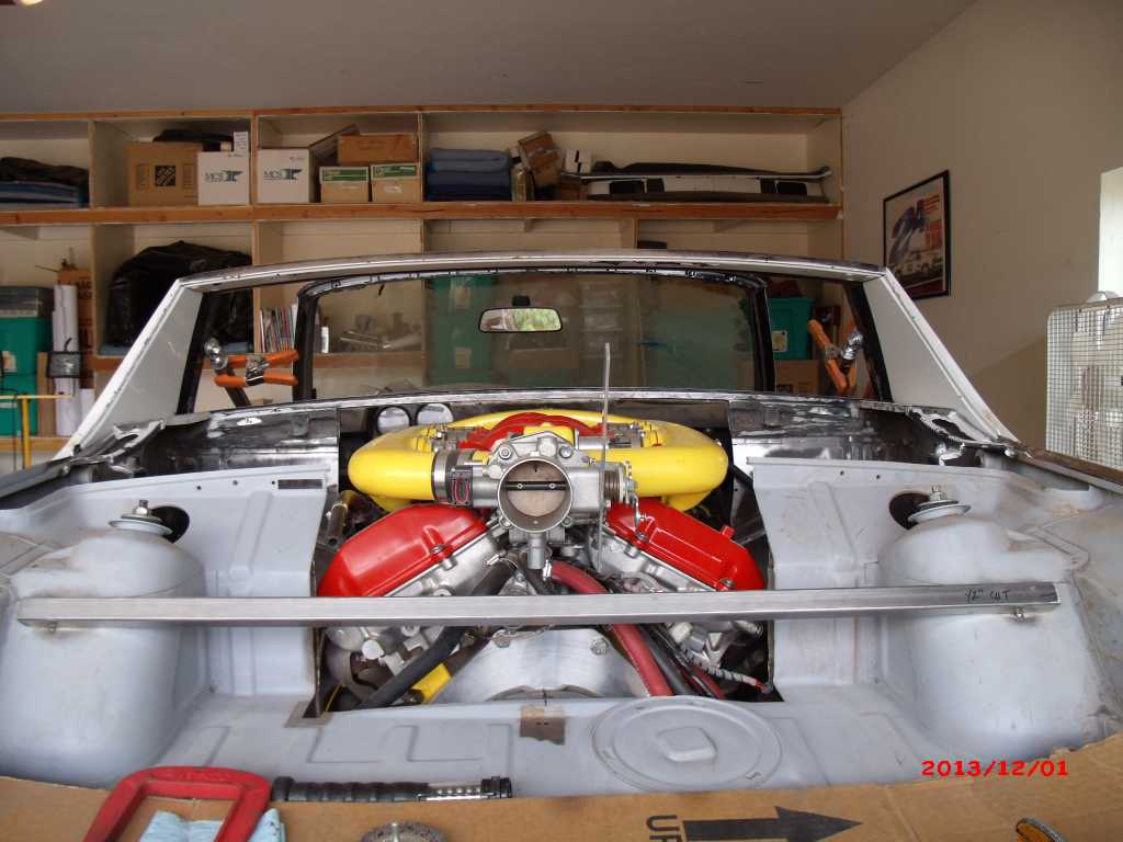
Doing another test fit. I widened the trunk cutout - partly for the left head and partly for the intake. Now I can get the motor to its full and proper height.
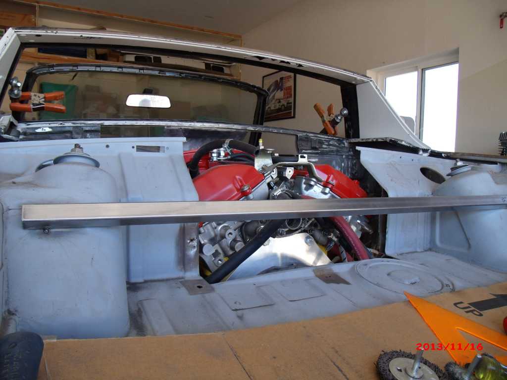 Things are looking good - although there are a few issues - so the bad first:
|
|
|
|
| 3d914 |
Nov 17 2013, 01:31 PM
Post
#305
|
|
Senior Member Group: Members Posts: 1,275 Joined: 24-September 03 From: Benson, AZ Member No.: 1,191 Region Association: Southwest Region |
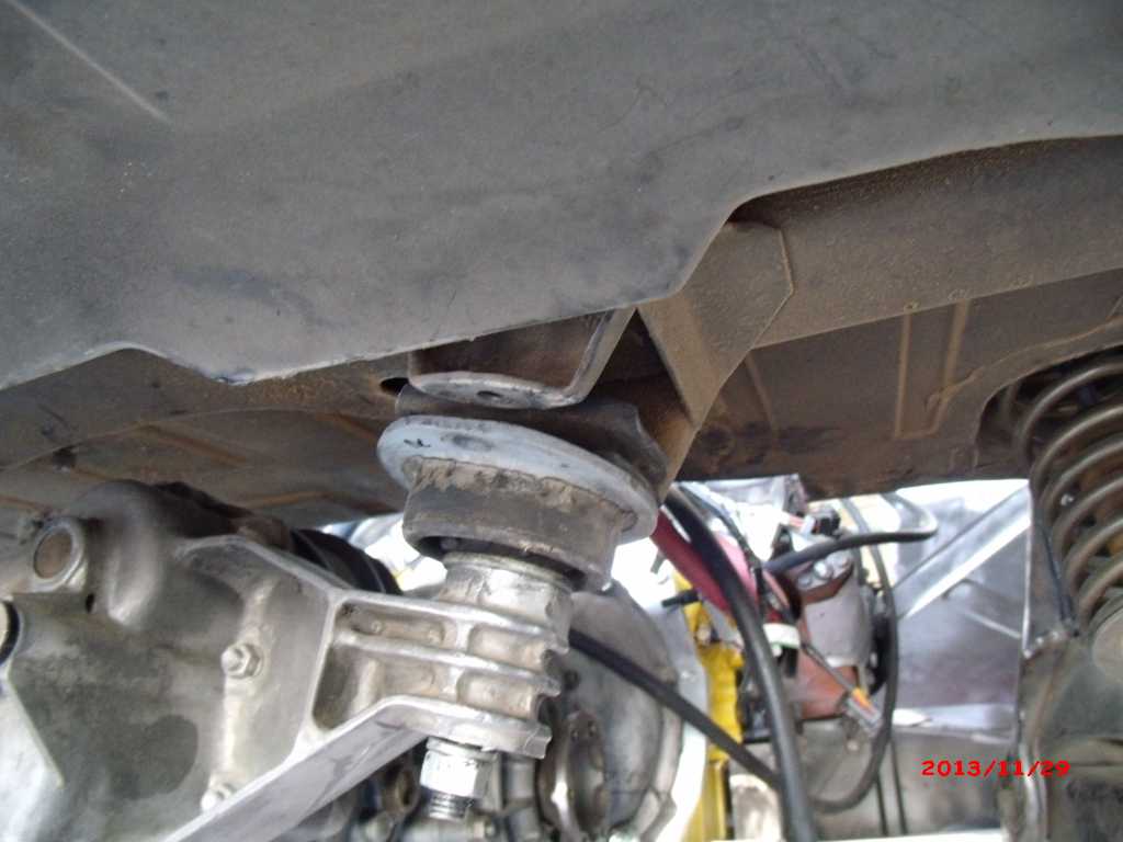
OK, now for the good. With the motor in the correct position I have all the expected height needed install the motor mounts on the 1.5in 12g square tubing. This will give me about 3/8in clearance between the engine bar and the forward oil pan.
Speaking of the oil pan, you can see that it will be just above the bottom of the under-body. 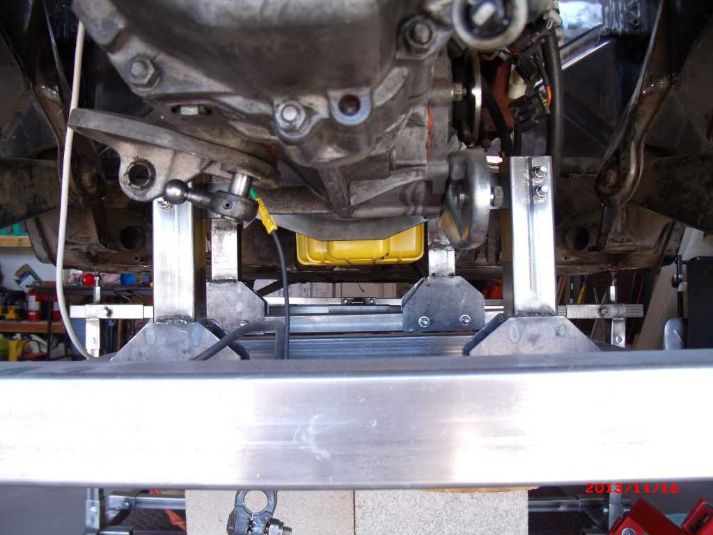 Also have good clearance for the alternator. 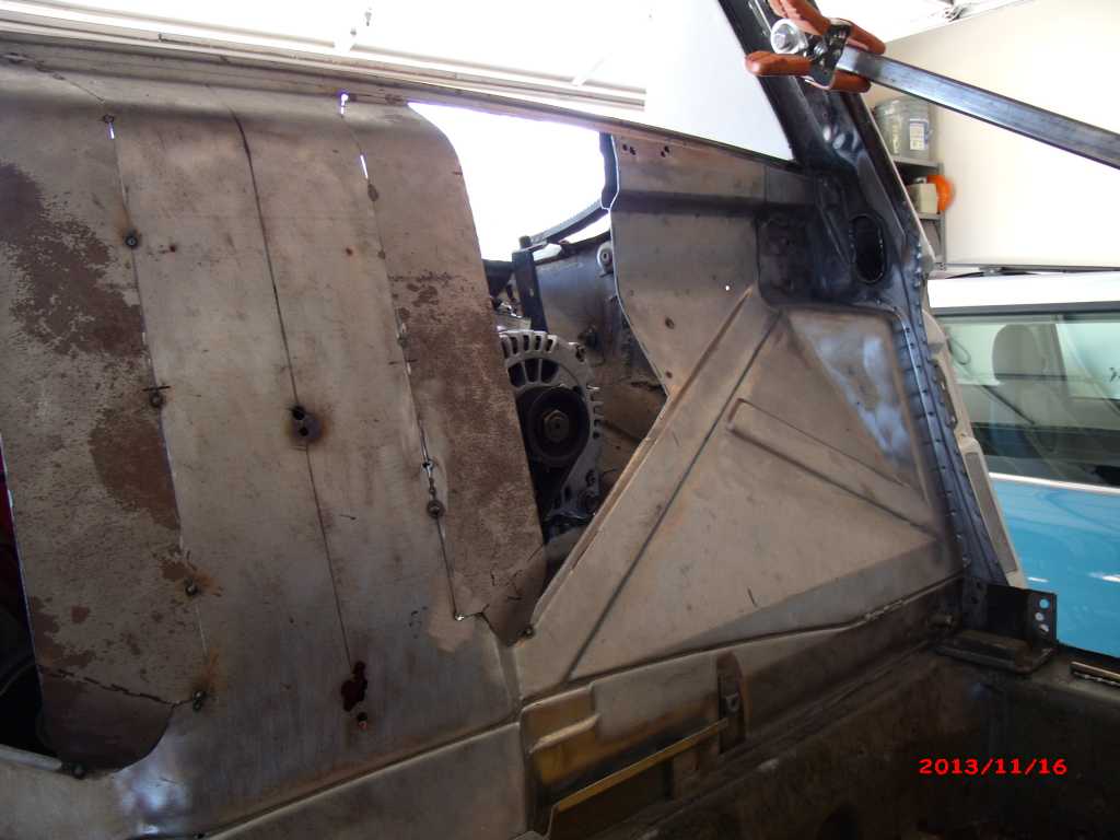 And good clearance for the power steering pump - soon to be A/C. 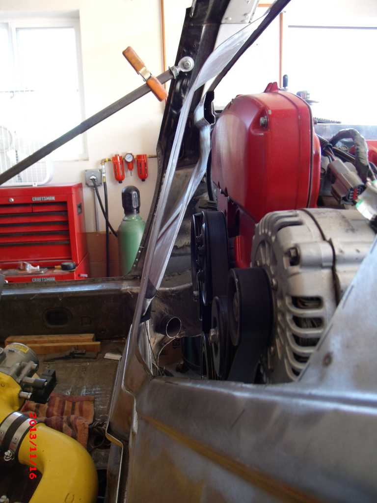 |
|
|
|
| 3d914 |
Nov 29 2013, 12:14 PM
Post
#306
|
|
Senior Member Group: Members Posts: 1,275 Joined: 24-September 03 From: Benson, AZ Member No.: 1,191 Region Association: Southwest Region |
Had several hours in the garage yesterday while my wife worked on dinner and her ancestry project. With the short days of sunlight and long days at work it's a nice break to work on the 914-SHO.
Did get the wiring done for the welder my neighbor let me borrow. I just added a connection to the 230/20a circuit for the compressor. Welder testing will get done this weekend. First I wanted to get the final mods to the trunk done. With the final rib gone on each side I should have no interference with surge tank or left head. 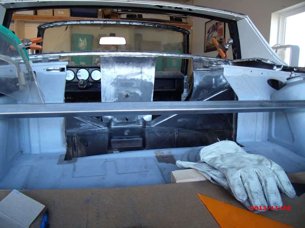 Also cut & drilled the pieces for the engine bar and mount disks. These sit on the 914's stock receiver where the stock engine bar hangs. Next step is to position the motor and locate the bar for final position. Left 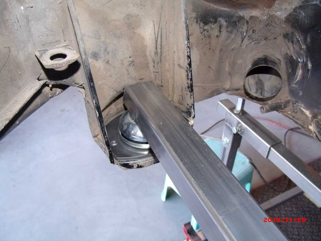 Right 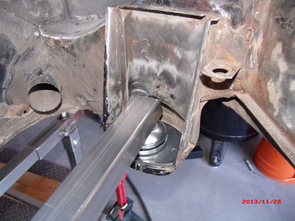 |
|
|
|
| 3d914 |
Nov 29 2013, 06:25 PM
Post
#307
|
|
Senior Member Group: Members Posts: 1,275 Joined: 24-September 03 From: Benson, AZ Member No.: 1,191 Region Association: Southwest Region |
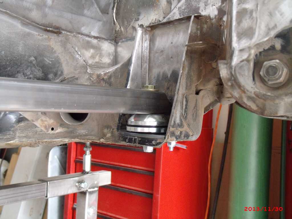
Did another test fit to verify dimensions before final drilling on the engine bar, and the bar receiver plate. I got the 3/8" clearance at the front oil pan, alignment at the drive hubs, and surprisingly really good alignment on the tranny mounts. I was expecting more than the 1/2" shown here, but I still have to mount the surge tank on top intake and check my height there.
 |
|
|
|
| 3d914 |
Dec 1 2013, 06:05 PM
Post
#308
|
|
Senior Member Group: Members Posts: 1,275 Joined: 24-September 03 From: Benson, AZ Member No.: 1,191 Region Association: Southwest Region |
Well Saturday I managed to get the engine bar, receiver plate, and biscuit mount positioned and drilled. Now I just need to do another fit to verify assembly and height with the surge tank on.
 |
|
|
|
| 3d914 |
Dec 1 2013, 06:10 PM
Post
#309
|
|
Senior Member Group: Members Posts: 1,275 Joined: 24-September 03 From: Benson, AZ Member No.: 1,191 Region Association: Southwest Region |
OK did another fit today and added the surge tank. It definitely changes a few things. You can see that the surge tank wanted to hit the front firewall, so I needed to lower the motor and move it back 1/2 inch. This give me good height and clearance for the tank.
  That means though that I don't have enough height for the biscuit mounts - they end up being too tall. That gives me plenty of clearance between the engine bar and the oil pan. 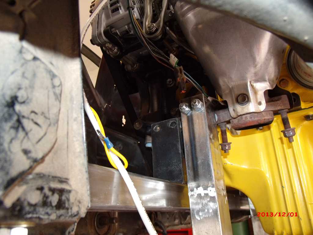 When I add the motor mounts on both sides - they do line up in the correct longitudinal position in relation to the engine bar, but when attached to the bar, they will close some of the large gap between the bar and the oil pan (to approx 3/8 in). Left motor mount Right motor mount 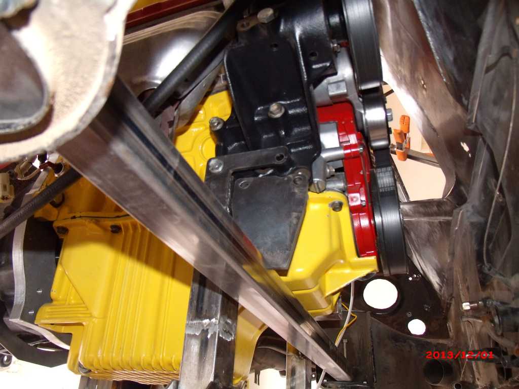 So overall the height and the length are proving to fit well. I only need to adjust the height between the engine bar and receiver plate. I figure I can do this with a thick high-density rubber washer. With this longitudinal position of the motor, I get good tranny drive shaft alignment to within 1/4 inch of centered. 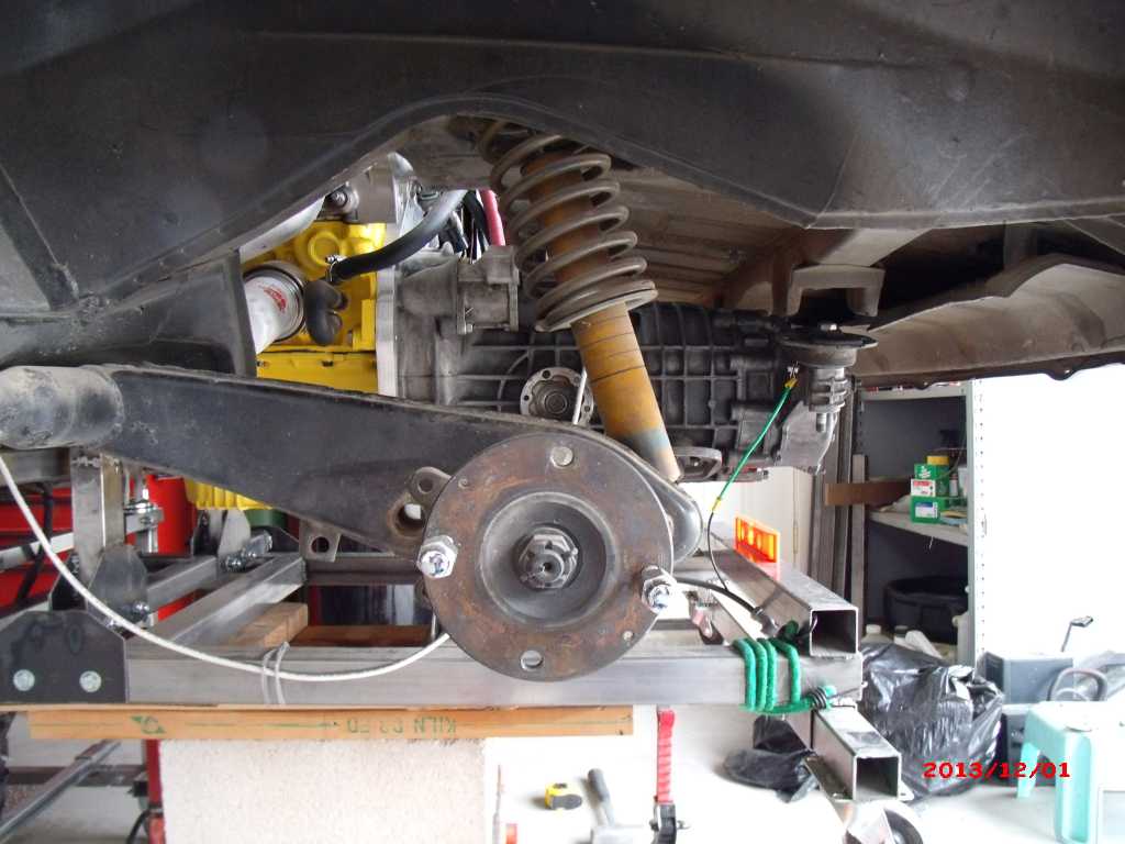 I also get the large gap I was expecting at the rear tranny mounts. So I will have to come up with either a custom mount, or a custom adapter plate to mount the stock pieces. 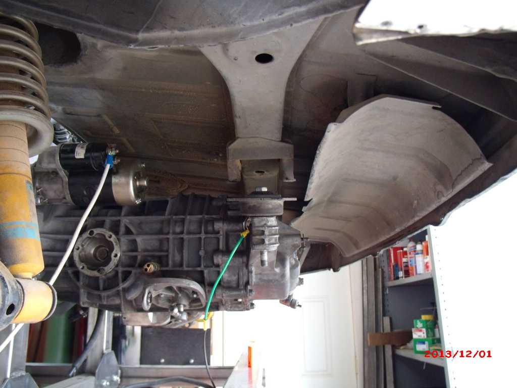 Attached image(s) 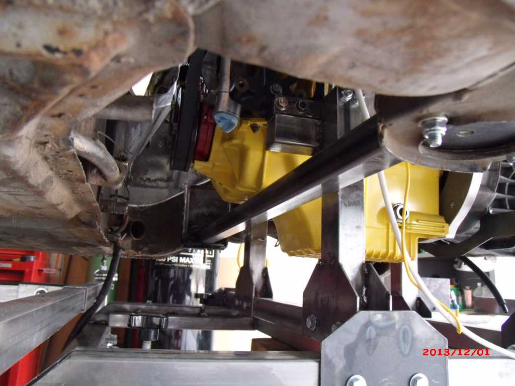
|
|
|
|
| Mike Bellis |
Dec 1 2013, 06:21 PM
Post
#310
|
|
Resident Electrician Group: Members Posts: 8,348 Joined: 22-June 09 From: Midlothian TX Member No.: 10,496 Region Association: None |
Just install a spacer like the Renegade cars. Their spacer also moves the tranny back 1.5 inches. But you could bolt the mounts up to the body and machine a spacer between the mount and the tranny.
The front brace being on top of the factory mount will make it hard to drop out the drivetrain. Will it not? BTW, please work faster because I like watching you progress... (IMG:style_emoticons/default/biggrin.gif) |
|
|
|
| 3d914 |
Dec 2 2013, 07:52 PM
Post
#311
|
|
Senior Member Group: Members Posts: 1,275 Joined: 24-September 03 From: Benson, AZ Member No.: 1,191 Region Association: Southwest Region |
QUOTE(Mike Bellis @ Dec 1 2013, 05:21 PM)  Just install a spacer like the Renegade cars. Their spacer also moves the tranny back 1.5 inches. But you could bolt the mounts up to the body and machine a spacer between the mount and the tranny. The front brace being on top of the factory mount will make it hard to drop out the drivetrain. Will it not? BTW, please work faster because I like watching you progress... (IMG:style_emoticons/default/biggrin.gif) Mike, I like your idea about a spacer between the mount and the tranny. The tranny has a slot for the bolt so it will accommodate the 1/4in off I expect to be. The bar will be free and clear when the engine dolly is lifted into place & attached. It takes the weight off the engine bar & mounts so they can be removed. With the tranny mount disconnected the whole thing will lower down with the dolly. Thanks for watchin. |
|
|
|
| 3d914 |
Dec 6 2013, 06:35 PM
Post
#312
|
|
Senior Member Group: Members Posts: 1,275 Joined: 24-September 03 From: Benson, AZ Member No.: 1,191 Region Association: Southwest Region |
Spent over five hours on the 914 today. Wish I had more to show for it. I started out getting the engine bar and motor mounts positioned so I could spot weld them in place. That went quite well.
 Now its just a matter of doing another fit check to get the tranny mount offset and the new position of the engine bar on the receiver. I got the motor mounts attached and was able to get everything positioned correctly. I was even able to drop the engine bar onto the receiver with 1/4in thick washers I found as Ace. From there I remeasured the offset at the tranny and it looks like the vertical offset will need to be 3/4in. The longitudinal alignment is right on the money. So then I just needed to mark the hole center from the engine bar to the receiver plate - which I did with a black marker. At least I though I did. Once I pulled everything down and looked for my marks - nada! Turns out the marker was too fat to reach all the way through the bar - missed by 1/16in. So I get to do that part over tomorrow. $#@$#@%! |
|
|
|
| Mike Bellis |
Dec 6 2013, 08:58 PM
Post
#313
|
|
Resident Electrician Group: Members Posts: 8,348 Joined: 22-June 09 From: Midlothian TX Member No.: 10,496 Region Association: None |
Most of the V8 kits have the bar hanging down below the oil pan. Although it's not ideal to have anything too low, the bar will take an impact before the oil pan does.
Your oil pan look like an easy target! Just something to think about... (IMG:style_emoticons/default/smile.gif) |
|
|
|
| 3d914 |
Dec 10 2013, 07:48 PM
Post
#314
|
|
Senior Member Group: Members Posts: 1,275 Joined: 24-September 03 From: Benson, AZ Member No.: 1,191 Region Association: Southwest Region |
QUOTE(Mike Bellis @ Dec 6 2013, 07:58 PM) Most of the V8 kits have the bar hanging down below the oil pan. Although it's not ideal to have anything too low, the bar will take an impact before the oil pan does. Your oil pan look like an easy target! Just something to think about... (IMG:style_emoticons/default/smile.gif) Mike, you make a good point. I've just never been that keen on the hanging bar - even for the stock motor. With this motor weighing so much more it just seems more stable resting on the receiver - plus I can use the neoprene washers to isolate some of the vibrations from the bar. Who knows though. Once I get this all settled in I still need to hook up the shift rod and exhaust and make sure I don't have any interference. That may change the whole ball game. |
|
|
|
| 3d914 |
Dec 25 2013, 05:05 PM
Post
#315
|
|
Senior Member Group: Members Posts: 1,275 Joined: 24-September 03 From: Benson, AZ Member No.: 1,191 Region Association: Southwest Region |
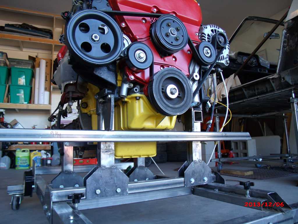
Last of my six days off so I needed to get something done. Spent the first four days driving over to TX and visiting my daughter for a couple days. Spent yesterday just catching up on stuff. But today I got some time on the project - mostly cleanup stuff.
Finished the welding & grinding on the engine bar/motor mounts. Decided to cap the ends also for a more finished look. Will get primer and paint soon. Tried out the mig/gas welder I borrowed and not too thrilled with it. The wire feed is way too fast, even on slow and the welds build up too high. I could probably track faster, but that makes it harder to push the beads so they overlap. 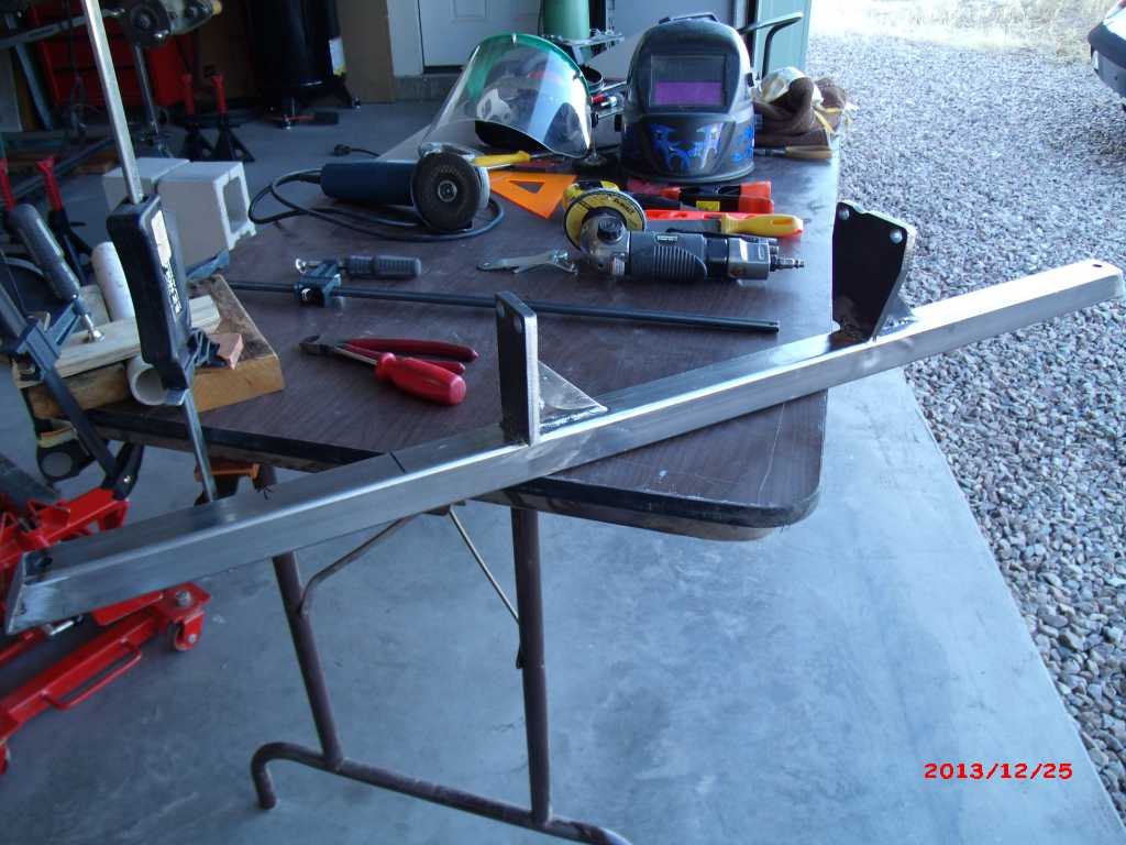 End cap 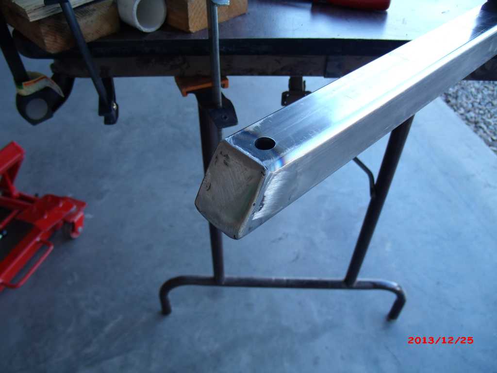 Also replaced the casters on the engine dolly. The rubber like wheels didn't role easily after some time so I went with steel wheels rated at 175# each. Much better. 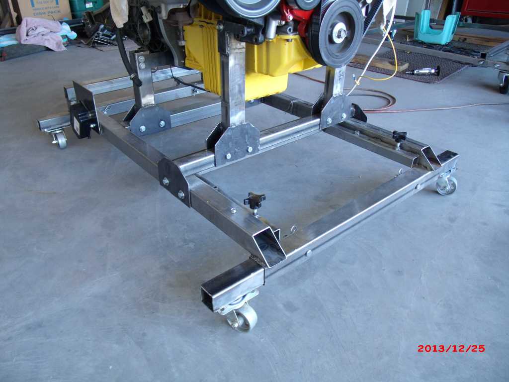 |
|
|
|
| Krieger |
Dec 25 2013, 05:21 PM
Post
#316
|
|
Advanced Member Group: Members Posts: 4,855 Joined: 24-May 04 From: Santa Rosa CA Member No.: 2,104 Region Association: None |
Looking good Gerard. Why don't you eliminate most of the rear firewall, or fab a new one farther back? Working on that engine once installed looks like it will be difficult.
|
|
|
|
| 3d914 |
Dec 25 2013, 07:09 PM
Post
#317
|
|
Senior Member Group: Members Posts: 1,275 Joined: 24-September 03 From: Benson, AZ Member No.: 1,191 Region Association: Southwest Region |
QUOTE(Krieger @ Dec 25 2013, 04:21 PM) Looking good Gerard. Why don't you eliminate most of the rear firewall, or fab a new one farther back? Working on that engine once installed looks like it will be difficult. Thanks Andy. I'm planning to relocate most of it 2.5in farther back. From your suggestion I suspect you mean I should widen it as well - which I may do. I was mostly expecting to have access for only basic maintenance - plugs, wires, accessory belt, etc, and expect to pull the motor for more difficult 50-60K mile tasks - valve cover gaskets, head gaskets, timing belts, etc. I also don't want to give up more of the rear trunk than I have to. Planning to do a lot of long-distance cruising in this car. |
|
|
|
| JRust |
Dec 25 2013, 07:31 PM
Post
#318
|
|
914 Guru Group: Members Posts: 6,317 Joined: 10-January 03 From: Albany Oregon Member No.: 129 Region Association: Pacific Northwest |
With your motor in place. It sure looks like it sits to high to have a stock engine lid or even the stock rear trunk lid. Sure looks like your intake sits about an inch over where the trunk lid should sit? Is it my old eye's? Or do you have custom trunk plans? Good looking project & nice to see you get some time to spend on it. Funny how they can sit for months with no work done. Then you spend a few hours multiple days & get so much accomplished. Wish I could master the minimum couple hours every week (IMG:style_emoticons/default/dry.gif)
|
|
|
|
| Krieger |
Dec 25 2013, 07:45 PM
Post
#319
|
|
Advanced Member Group: Members Posts: 4,855 Joined: 24-May 04 From: Santa Rosa CA Member No.: 2,104 Region Association: None |
Relocate the new firewall back to where you have that square tubing tacked in. You probably know a lot of the v 8 guys hack the entire area out. I welded a piece of angle iron vertically in the corner between the long and the shock tower.
|
|
|
|
| 3d914 |
Dec 27 2013, 07:14 PM
Post
#320
|
|
Senior Member Group: Members Posts: 1,275 Joined: 24-September 03 From: Benson, AZ Member No.: 1,191 Region Association: Southwest Region |
QUOTE(JRust @ Dec 25 2013, 06:31 PM) With your motor in place. It sure looks like it sits to high to have a stock engine lid or even the stock rear trunk lid. Sure looks like your intake sits about an inch over where the trunk lid should sit? Is it my old eye's? Or do you have custom trunk plans? Good looking project & nice to see you get some time to spend on it. Funny how they can sit for months with no work done. Then you spend a few hours multiple days & get so much accomplished. Wish I could master the minimum couple hours every week (IMG:style_emoticons/default/dry.gif) JRust - thanks. I do have a custom engine lid/trunk planned. Both lids will get a raised middle section to accommodate the tall intake manifold. In fact Andy (below) has similar trunk config I'm planning - so the rear trunk opens hinged at the back instead of the front. (IMG:http://www.914world.com/bbs2/uploads/post-2104-1285521045_thumb.jpg) In addition, I want to connect the back of the engine lid and hinge it to the front of the trunk, so when the trunk opens then engine lid slides back and up with it. QUOTE(Krieger @ Dec 25 2013, 06:45 PM) Relocate the new firewall back to where you have that square tubing tacked in. You probably know a lot of the v 8 guys hack the entire area out. I welded a piece of angle iron vertically in the corner between the long and the shock tower. Nice project Andy. I like the trunk lid mod. Got any details on that. I saw your picture of the trunk firewall modifications. Did you remove the double-walled portion before adding the angle? (IMG:http://www.914world.com/bbs2/uploads/post-2104-1285520093_thumb.jpg) |
|
|
|
|
1 User(s) are reading this topic (1 Guests and 0 Anonymous Users)
0 Members:

|
Lo-Fi Version | Time is now: 9th May 2026 - 09:31 PM |
Invision Power Board
v9.1.4 © 2026 IPS, Inc.