Full Version: Gauging interest for PnP Megasquirt solution
What are you using to trigger the MS then? Just the signal from the dizzy?
QUOTE(velum @ Sep 24 2010, 09:38 PM) 
Hi James!
Anything new about your PnP MegaSquirt solution? I have a '73 914-4 2.0L and I would be interested. Also, are you thinking of providing a solution that would allow to get rid of the distributor? I heard all this can be done electronically. And what about injectors, do you use stock injection valves, or do you recommend swapping them for modern ones?
Cheers!
JF
It has been slow going as my schedule has not permited me to get much work done latley. I did however make a major decision on the direction i was going in and have started working on something new, but i will get to that later... As for getting rid of the distributor that should not be to hard with megasquirt, you just need a crank trigger, or some other trigger setup and you could go with a wasted spark arangement or maybe a coil on plug setup. I have yet to see data showing any advantage of those systems on our motors though and i am not sure if they justify the extra cost/complexity for most people. I like to lean towards a keep it simple design philosophy whenever possible. As for injectors i use the sock ones because they fit so nicely into the stock intake runners. You could run just about any injector you like as long as it is sized correctly for the application but I feel if it aint broke, dont fix it if you have the stock ones and they work then stick with them.
Back to the subject of my current work, originally i had posted this topic to find a use for some extra Mini-MS boards that i had left over from my own project. Most of the cost in PCB production is the initial setup, after that it does not cost much more for 20 boards then it does for one, so even though I only needed a couple for my own cars i had a bunch of extras made up. I initially thought of just building in the same way i had done with my own car for anyone that was intrested in them however intrest was greater then i had expected and various issues were raised that started me in a different direction. Adapting the mini-ms board inside the d-jet case in order to make a plug and play type solution is somewhat labor intensive, and while i would not have minded doing it for a few people here and there, on a larger scale it is not something i think i would want to undertake or deal with supporting. There is to much custom work getting the board mounted in the d-jet case and soldering of custom wiring to get it to work the way i want it to and in addition to being tedious i see every extra wire joint as another source of potential failture. It is a fine solution for the DIY'er but if i am looking at a small scale production for other people I would like to deliver something that is less of a hack.
SO...
For any DIY'er intrested in duplicating what i have already done I still have extra Mini-MS PCB's that i am willing to get rid of for cheap and i am always willing to share any informaton on my setup.
BUT...
For people looking for more complete PNP solution what i have decided to do is just design my own PCB that addresses the issues i see when building a plug n play solution from an existing megasquirt board. This new board i am working on is of the proper dimensions to act as a drop in replacement for for the PCB in the stock D-jet ECU. All the signlas will be brought to their proper locations on the d-jet connector and the injector circuit will be modified on the board to allow it to work with the stock d-jet harness with no modification. It will mount using the same screws/holes that the stock board does and solder directly to the stock ECU connector so there will be no rigging up of custom mountings or jumper wires in the ECU. Basically, I am taking everything I have learned with MS this far and all my personal modifications and building them into a PCB that will fit properly in the stock case.
I finally took the plunge and made time in my schedule to start on this last week. So far i have made a custom part in Eagle for the d-jet connector, finished most of the board schematic and have just started working on the component layout and routing. I decided to pause at this point as i am trying decied what, if any, other features to add to the board itself. Being that this is a totally new board i am in a unique situation of being able to add any of the other megasquirt modifications out there directly to the main board itself I decided that i should give serious thought to some of the features that are out there before i settle on a final design. While most of these features can be attached later I would like to have the ones most likely to be used built into the board iteslf. The one that is getting the most consideration right now is a 2nd MAP sensor for constant Baro correction as i feel this might be usefull. I still need to test this on my current setup though. I will be posting another thread looking to get peoples input on features.
![popcorn[1].gif](http://www.914world.com/bbs2/style_emoticons/default/popcorn[1].gif)
QUOTE(draganc @ Sep 25 2010, 06:43 PM)
What are you using to trigger the MS then? Just the signal from the dizzy?
One car I have setup as fuel only, it pulls the tach signal from the coil. My autox car gets its signal from a pertronix unit set up with a pullup resistor in a dizzy with locked advanced mech, the MS then controls the advance and triggers a CD box. Its a pretty easy setup to do on a stock car keeps it looking pretty stock and for me at least was an improvement over the stock dizzy that was in there. A crank trigger would probably be a better choice overall but this is an easier way to go.
because people like pictures...
Still have a long way to go, but you get the idea. I am new to Eagle and finding it to be a bit quirky at times.
The outline is the full dimensions of the d-jet board, the extra vertical line is my current target for fitting all the components in, hopefully when i am done it will be even smaller then that.
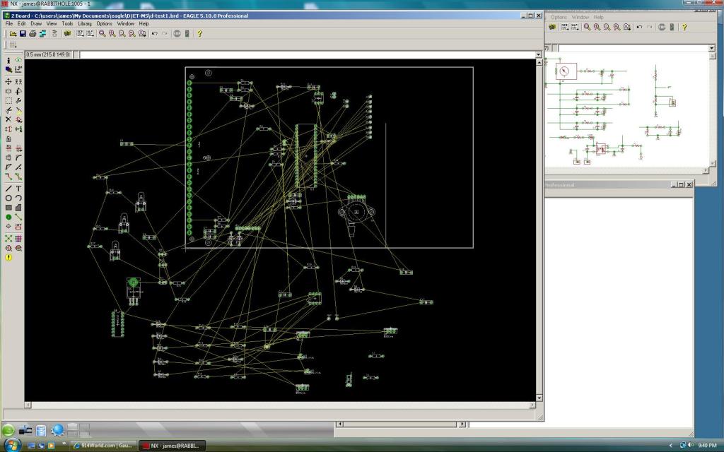
in case anyone is wondering.... from a windows box remoted into my linux server running a windows app an emulated environment. A little strange but it allows me to squeeze in work on it in my free time during the day.
Still have a long way to go, but you get the idea. I am new to Eagle and finding it to be a bit quirky at times.
The outline is the full dimensions of the d-jet board, the extra vertical line is my current target for fitting all the components in, hopefully when i am done it will be even smaller then that.
in case anyone is wondering.... from a windows box remoted into my linux server running a windows app an emulated environment. A little strange but it allows me to squeeze in work on it in my free time during the day.
Hi James!
Thanks for that update about where you're at with the project. I am seriously thinking of converting my car to MS within the next year. The solution does not have to be totally PnP, but I don't wan't it to be complicated either. I am not racing with my car, so I just want a solution for normal driving that will replace my d-jet. Of course, with modern technology, I am expecting the performances to improve a bit.
Would it be possible for you to give me a list of items I will need to convert my '73 914-4 2.0L to MS with a ballpark price for these items? If you can send me that, please also identify the items you can provide me with. Just list items for a fairly standard setup. I just installed a new FI wire harness in my car, so I would like to reuse it if possible.
Cheers!
JF
My machinist friend used to dragrace a t3. He modified a few hei chevy distributors for the t1. Won't the t1 dist fit a t4? Those hei were pretty easy to cut down to fit the t1 and had the coil and all in the cap. He just used everyother plug wire in the cap. They are big though and may not fit the t4 tin. The t4 dist modded like you describe may be a cleaner setup except for the cd box though but the hei stuff is regularly available. If the overall size of the hei is a problem maybe a 4 cylinder later model electronic distributor could be found and made to fit in the t4. The base of the dist is pretty simple. I probally am making this more complicated than it really is though. In the early 70's I bought some electronic conversions for the t1 from montgomery wards that worked good till the potting epoxy melted out of them. They were just the wheel and pickup that went in the dist and a small box about 2.5x3.5x1.25.and the short wiring harness between the dist and the box with the power and ground lead. Course you still needed the mechanical and vaccum advance. I like the ms for making your own advance curve much better. Stock looking isn't important to me. Easy to do maintenance and easy to find parts and reliability are my main concerns.
QUOTE(charliew @ Sep 26 2010, 05:37 AM)
My machinist friend used to dragrace a t3. He modified a few hei chevy distributors for the t1. Won't the t1 dist fit a t4? Those hei were pretty easy to cut down to fit the t1 and had the coil and all in the cap. He just used everyother plug wire in the cap. They are big though and may not fit the t4 tin. The t4 dist modded like you describe may be a cleaner setup except for the cd box though but the hei stuff is regularly available. If the overall size of the hei is a problem maybe a 4 cylinder later model electronic distributor could be found and made to fit in the t4. The base of the dist is pretty simple. I probally am making this more complicated than it really is though. In the early 70's I bought some electronic conversions for the t1 from montgomery wards that worked good till the potting epoxy melted out of them. They were just the wheel and pickup that went in the dist and a small box about 2.5x3.5x1.25.and the short wiring harness between the dist and the box with the power and ground lead. Course you still needed the mechanical and vaccum advance. I like the ms for making your own advance curve much better. Stock looking isn't important to me. Easy to do maintenance and easy to find parts and reliability are my main concerns.
I believe type I and IV distributors are interchangeable as i have seen the same part used on both motors before. I am intrested in gettting more information on some of the wasted spark setups i have seen sold for type I's and how they trigger. What i am most intrested in checking out at the moment though are some of the late model vanagon parts. Its been a long time since i sold my vanagon but from what i remember the distributor looked similar to the ones used in type I's and 4's but had some sort of a trigger wheel in them. Also the late 2.1 vanagon throttle body with the 50mm bore looks as though it could be made to bolt on a 1.8 plenum.
QUOTE(velum @ Sep 25 2010, 11:01 PM)
Hi James!
Thanks for that update about where you're at with the project. I am seriously thinking of converting my car to MS within the next year. The solution does not have to be totally PnP, but I don't wan't it to be complicated either. I am not racing with my car, so I just want a solution for normal driving that will replace my d-jet. Of course, with modern technology, I am expecting the performances to improve a bit.
Would it be possible for you to give me a list of items I will need to convert my '73 914-4 2.0L to MS with a ballpark price for these items? If you can send me that, please also identify the items you can provide me with. Just list items for a fairly standard setup. I just installed a new FI wire harness in my car, so I would like to reuse it if possible.
Cheers!
JF
Wanting to use a replacement harness I had my car was on of my primary motivating factors in doing the conversion in the way that i did, the downside though is you will have to destroy a stock ECU to source the connector. Other then that, if you already have d-jet on your car you dont need to purchase a whole lot as you can use the stock sensors and injectors. The only d-jet part that wont carry over is the TPS so you will either have to source one that is compatable with MS or use a resistor on the TPS signal line to fix it and then use MAPDOT Accel.
Really all you will need is a stock ECU to source the connector from, the MS itself, a MS relay board if you want to make things a little easier, resistors for the injectors, and wire to hook it all up.
QUOTE(JamesM @ Sep 26 2010, 02:24 PM)
QUOTE(velum @ Sep 25 2010, 11:01 PM)
Hi James!
Thanks for that update about where you're at with the project. I am seriously thinking of converting my car to MS within the next year. The solution does not have to be totally PnP, but I don't wan't it to be complicated either. I am not racing with my car, so I just want a solution for normal driving that will replace my d-jet. Of course, with modern technology, I am expecting the performances to improve a bit.
Would it be possible for you to give me a list of items I will need to convert my '73 914-4 2.0L to MS with a ballpark price for these items? If you can send me that, please also identify the items you can provide me with. Just list items for a fairly standard setup. I just installed a new FI wire harness in my car, so I would like to reuse it if possible.
Cheers!
JF
Wanting to use a replacement harness I had my car was on of my primary motivating factors in doing the conversion in the way that i did, the downside though is you will have to destroy a stock ECU to source the connector. Other then that, if you already have d-jet on your car you dont need to purchase a whole lot as you can use the stock sensors and injectors. The only d-jet part that wont carry over is the TPS so you will either have to source one that is compatable with MS or use a resistor on the TPS signal line to fix it and then use MAPDOT Accel.
Really all you will need is a stock ECU to source the connector from, the MS itself, a MS relay board if you want to make things a little easier, resistors for the injectors, and wire to hook it all up.
Hi James!
I have 2 spare ECUs and one is not working properly already (fuel pump won't work with it), so I don't mind trashing this one. I believe there are various types of Megasquirts (I, II, III) though... From what I understand, you are using MS-2. Would MS-3 be good too? Also, won't I need a wideband 02 sensor? I don't see this in your list of parts needed.
Are you still selling mini-MS parts? Are these printed circuits only, or assembled boards with all the components? Price? From what I read in this thread, you made it so it can be inserted in the original ECU case. However, I have read documentation about MS telling that it should not be located under the hood because of extreme conditions (heat).
I had a look at www.diyautotune.com, but what parts I would need to order exactly is still an enigma for me after looking at the site. Is there a list somewhere on the web with exact part numbers of what is needed?
Sorry for all those questions... all this is quite new to me, and I am still in the process of absorbing all this information.
Cheers!
JF
P.S. I don't mind doing a bit a soldering, but I don't think I have enough experience to do a good job at soldering all the components on a bare printed circuit board.
QUOTE(JamesM @ May 4 2010, 05:43 PM)
Bosch 0 280 122 001 might work for you.
Its used on a whole bunch of different cars. It has the correct shaft shape and can be mounted on the plate from the stock TPS at about a 45 deg angle if you space it out about half an inch.
Thats what i have been using for the last 3 years anyways. I would like to find a cleaner looking soultion though.
You may find that Bosch 0 280 120 402 fits better. I have used it on other MegaSquirt retrofits on D-Jetronic cars, albeit not the 914. Given that the 914 setup is the same, it will bolt straight on with correct angle, depth and all. You'll find them in BMW e34 M20 automatic cars. Be sure to get the unusual connector as well. They are expensive new, so look for a used one.
- Karl
QUOTE(velum @ Sep 26 2010, 03:35 PM)
Hi James!
I have 2 spare ECUs and one is not working properly already (fuel pump won't work with it), so I don't mind trashing this one. I believe there are various types of Megasquirts (I, II, III) though... From what I understand, you are using MS-2. Would MS-3 be good too? Also, won't I need a wideband 02 sensor? I don't see this in your list of parts needed.
Are you still selling mini-MS parts? Are these printed circuits only, or assembled boards with all the components? Price? From what I read in this thread, you made it so it can be inserted in the original ECU case. However, I have read documentation about MS telling that it should not be located under the hood because of extreme conditions (heat).
I had a look at www.diyautotune.com, but what parts I would need to order exactly is still an enigma for me after looking at the site. Is there a list somewhere on the web with exact part numbers of what is needed?
Sorry for all those questions... all this is quite new to me, and I am still in the process of absorbing all this information.
Cheers!
JF
P.S. I don't mind doing a bit a soldering, but I don't think I have enough experience to do a good job at soldering all the components on a bare printed circuit board.
I have actually always used the old and cheap MS1 with the 2.2 board layout on my own cars. Originally with the genuine B&G 2.2 board and then later with the mini-ms board which is based on the 2.2 schematic. I did do one install on a friends 914 with a MS1 on the 3.0 board as well but really did not see any advantage when doing a fuel only install. I could see some usefullness in running the MS2 chip given its larger memory, higher clock speed and greater resolution but so far MS1 with the Hi-res variant of the MSnS Extra code has done everything i needed it to(as well as a lot of extra stuff i dont even need)
Technially you dont "need" a wideband sensor to run MS but you dont want to try and tune it yourself without one. Its always the first part i buy when doing a conversion as it is a usefull thing to have on any old car.
As far as mounting in the engine compartment goes, the MS manual does state not to do it for environmental concerns. The standard MS case is not weather proof and underhood temps could exceed the specs of some of the MS onboard components. My original install with a 2.2 board I followed these instructions and used the MS relay board mounted to the stock ECU location and ran a relay cable to the MS in the passenger compartment. I ran it like this for years but was never happy with the extra wires and runnning the realy cable into the passenger compartment. On most cars I would not think of running the MS under the hood because under the hood usually means right next to the exhaust and fully insulated trapping a bunch of heat in. 914's are a little different with the exhaust below the engine shelf and cooling tin and you have a constant airflow comming through the engine bay to cool the motor. Part of my testing right now is involving mounting a temp probe at various locations in the engine compartment and inside the ECU on various components to see just how hot everything is getting. So far though it has gone through one autox season in its current configuration in the engine bay with no problems. As for moisture, most people with 914's try and avoid water like the plague, living in utah though i always seem to get hit with a random downpour when i least expect it. If you can fit your board into the stock ECU case it can be sealed up pretty well. Of all the stock ECUs I have opened up only 1 showed any signs of water damage inside it and I believe it was only because it had been treated pretty badly, run without the proper seal on the wiring harnes and hit with so much battery acid it had almost correded through. You can also coat your board to protect it from moisture in the air. Properly installed i dont think it will be seeing any more mosture then it would mounted in the passenger compartment, maybe less depending on what shape your targa seals are in. I had an autox at Alta ski resort that got rained out and wound up driving 26 miles, decending 4000ft on mountain roads, in hard rain with zero issues. This is all with the board mounted in the engine compartment. I still want to put it through more long term testing before saying 100% its an ok thing to do, but so far i have been beating the crap out of it with no problems. My current thoughts are that if you are using a relay board then mount the ECU in the most environmentally friendly place possible, if not and you are mounting in the stock location then just make sure you are sealed properly from the elements. If i suffer a failure running this way i will be sure to let everyone know.
The parts you need to get from DIYautotune really depend on what system you want to run and how you want to do your install. Pieceing together your own fuel injection system is something that should be done with a lot of forethought and research. I think at this point every MS install that has been done in a 914 has at least in some way been slightly different from one another. There is not set way to do it so the best thing to do if you are going it on your own is to read as much you possibly can, familarize yourself with the system and components and deciede which way you want to go with it. Read through the megasquirt manual as well as the info on the MSnS extra code, i recomend reading it all more then once. Read up on other peoples installs in 914's as well as other d-jet cars and just suck up as much information as possible. Reading up on how d-jet works is helpfull as well when adapting the systems. I can tell you the exact specifics of what i have used in the past, but as you are going to be doing all the wiring yourself these are all subjects that you want to be familar with.
The basics you will need are:
#1 an ECU - Lots of options here with different board versions processors. I have used the MS1 v2.2 which is the most basic one available so really any of them should be able to work just fine, even the microsquirt should be able to be made to work. It just comes down to how much money you want to spend and what sort of features you want.
Really the ECU is all you need if you already have a d-jet system running however there are some other things you might want to get in order to make the process easier as well as items that are related to how you are setting up your system.
#2 MS relay board - Good to have if you dont want to mount the ECU in the engine compartment, makes the wiring a lot easier. Simplifies things a lot if this is your first install.
#2b Relay cable - needed if running a relay board - dont use a homemade one with soldercup connectors or you are just asking for problems.
#3 wideband 02 sensor setup
#4 Temp Sensors - MS is setup by default to use stock GM temp sensors- some people use these and adapt them to the 914, other people flash the MS ECU to read the stock d-jet sensors.
#5 Throttle position sensor - if you are going to use one
#6 Resistors for the injectors - if you are going to use them
I could probably type on this subject all night but your best bet is just to read what is out there first. Start here is a to give you a basic idea of what you are getting into. Its a lighter read then diving right into the megamanual and has some usefull d-jet/MS information.
http://www.1800philes.com/tuning_article.html
As for the Mini-MS boards i have no idea what the current licenseing situation of these boards is so i am reluctant at this pont to sell any assembled units. I do have some extra PCB's though if anyone wants to assemble them themselves, i just dont want to get involved in higher $$$ transactions when licenseing issue are in question. I will let them go with the understanding that these are experimental and unsupported for $20 basically to cover production and shipping costs. I have about 10 of these that i will get rid of at which point i will not getting any more made. Instead i will be focusing on my own boards designed specifically for d-jet replacement which after they are completed and tested i will work with B&G to get a proper licence to sell them.
I'll tke a shot at one of your boards - sending PM
Hi James!
Thank you so much for all that information! I is much appreciated. I showed this to a guy who has a dyno and who installs MegaSquirts close by where I live. I think what I'd like is a wasted spark setup with a dented wheel attached to the engine for timing. I am not sure yet where that wheel should be attached. I would prefer to do both fuel and ignition and to get rid of the distributor.
Where did you put your O2 sensor? In the muffler? I am asking because my heat exchangers have separated pipes, so the exhaust gas only mixes once in the muffler.
Cheers!
JF
On my autox car i have the sensor installed just after the 4-1 collector on the header, on my street car i run a bursch and have it installed after the Y's but before the muffler. I have not installed an o2 sensor in a stock muffler before and dont know of a good way to do it. Perhaps someone that has cut one open before might have a sugestion. I have a 1.7 wiht a stock muffler that i am going to convert as well but i picked up a bursch specifically for this purpose.
Technically the O2 sensor is optional, and while it is really nice to have it is not manditory if you already have your fuel maps dialed in. If you have access to one you could tune the system on a dyno without a permanently installed o2 sensor. I dont have access to a dyno so i need the wideband in the exhaust when tuning.
If i was going to go distributor-less i would probably go with something like McMarks setup. I have not used it personally but it looks like a good setup that tucks away nice.
http://www.914world.com/bbs2/index.php?sho...l=trigger+wheel
Hi James!
Thank you so much for all that information! I is much appreciated. I showed this to a guy who has a dyno and who installs MegaSquirts close by where I live. I think what I'd like is a wasted spark setup with a dented wheel attached to the engine for timing. I am not sure yet where that wheel should be attached. I would prefer to do both fuel and ignition and to get rid of the distributor.
Where did you put your O2 sensor? In the muffler? I am asking because my heat exchangers have separated pipes, so the exhaust gas only mixes once in the muffler.
Cheers!
JF
Technically the O2 sensor is optional, and while it is really nice to have it is not manditory if you already have your fuel maps dialed in. If you have access to one you could tune the system on a dyno without a permanently installed o2 sensor. I dont have access to a dyno so i need the wideband in the exhaust when tuning.
If i was going to go distributor-less i would probably go with something like McMarks setup. I have not used it personally but it looks like a good setup that tucks away nice.
http://www.914world.com/bbs2/index.php?sho...l=trigger+wheel
QUOTE(velum @ Sep 27 2010, 05:30 PM)
Hi James!
Thank you so much for all that information! I is much appreciated. I showed this to a guy who has a dyno and who installs MegaSquirts close by where I live. I think what I'd like is a wasted spark setup with a dented wheel attached to the engine for timing. I am not sure yet where that wheel should be attached. I would prefer to do both fuel and ignition and to get rid of the distributor.
Where did you put your O2 sensor? In the muffler? I am asking because my heat exchangers have separated pipes, so the exhaust gas only mixes once in the muffler.
Cheers!
JF
QUOTE(JamesM @ Sep 28 2010, 12:15 AM)
On my autox car i have the sensor installed just after the 4-1 collector on the header, on my street car i run a bursch and have it installed after the Y's but before the muffler. I have not installed an o2 sensor in a stock muffler before and dont know of a good way to do it. Perhaps someone that has cut one open before might have a sugestion. I have a 1.7 wiht a stock muffler that i am going to convert as well but i picked up a bursch specifically for this purpose.
Technically the O2 sensor is optional, and while it is really nice to have it is not manditory if you already have your fuel maps dialed in. If you have access to one you could tune the system on a dyno without a permanently installed o2 sensor. I dont have access to a dyno so i need the wideband in the exhaust when tuning.
If i was going to go distributor-less i would probably go with something like McMarks setup. I have not used it personally but it looks like a good setup that tucks away nice.
http://www.914world.com/bbs2/index.php?sho...l=trigger+wheel
This is very interesting!
Thanks for the link!
JF
I work 60+ hours a week take a 1/2 load in school... my wife just saw this and told me i still have to much time on my hands 
I have a layout done and fully routed. This is really rough, still a ways off before i send it off to get printed. I am still playing around with it, there are a couple symbols that i want to create custom librarys for, and a few other things then i need to double check everything again. Final layout my look nothing like this. But in the mean time for everyones viewing enjoyment...
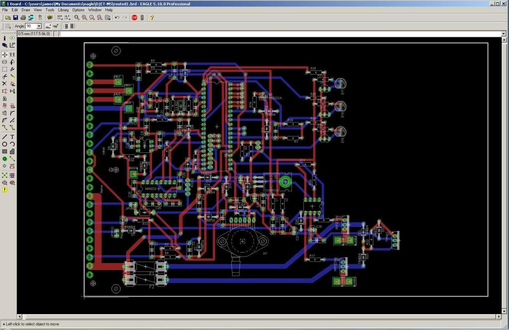
I have a layout done and fully routed. This is really rough, still a ways off before i send it off to get printed. I am still playing around with it, there are a couple symbols that i want to create custom librarys for, and a few other things then i need to double check everything again. Final layout my look nothing like this. But in the mean time for everyones viewing enjoyment...
James...Wow...this is intriguing. I have not followed the whole thread, but what I surmise is that you are developing a MS ECU board, for fuel-only control, that could be mounted into the D-Jet ECU case?
This would utilize the existing 914 FI harness, relay board, fuel injectors TS1 and TS2?
You would eliminate the standard D-Jet MPS and trigger points?
If so, a couple of thoughts/observations you may have considered. Not critical, trying to help your progress, just to be sure:
1. Your efforts are commendable and if it all works out, this could be a windfall for 914 owners. Plug N Play would be the goal.
2. The offering could include standard 1.7, 1.8, 2.0L fuel maps for standard set-ups (reprogrammable of course for those so-inclined), so its a bolt on for most owners.
3. Reusing the existing FI harness would mean the MPS, trigger point branches could simply be cut off. The 3 ground branches would remain - 2 for the injectors and the third for the ECU/TPS ground...is this acceptable? Would a supplemental engine-chassis ground cable be advised? This assumes the FI harness is still viable and functioning after all these years which may be a stretch for some harnesses. New FI harnesses could be fabricated without uneeded circuits or with modifications as you specify.
4. Wasn't it true that for 2.0L injectors/systems, the MS does not have sufficient pulse width resolution, pulses were too rich - has MS changed or is this resolved? Dave Hunt burned up motors because of this and switched to SDS. Would injector changes or PWM be needed?
5. EMI has been a huge issue for several of the 914world members who have tried this conversion, these low volt PEFI systems are notorious for this...does the existing harness accommodate this or is internal shielding needed on certain circuits?
6. D-Jet injectors require power resistors...are these on the new board?
7. Your circuitry suggests that the existing AAR and CSV are used correct? Is the CSV turn-off after the starter quits, ECU controlled?
8. Maybe the four MPS wires, now not needed, could be preassigned on the new board to accommodate an O2 sensor for closed loop? A connector could be mounted to these wires and a supplemental harness run back to the O2 sensor.
Rock-on
Yes plug and play, or at least as close to it as possible is the goal. This board however is just basically the next step in what i have been working on all along.
While i had originally played with the idea of building some extra Mini-MS boards into a plug and play solution for anyone who wanted them, the response i got was greater then I had expected. I had thought originally that the people most intrested in this would be the experimenters but the idea seemed to have a more widespread apeal, and while i would not have minded delivering what i was running in my own car to a small number of people for various i did not want to do it on a large scale. As there seemed to be a desire/need for a product of this sort though I set my sights on solving the problems i saw with delivering on a larger scale the greatest one being the complexity and time involved with the build followed closely by questions of durability specifically of the soldered connections to the main ECU connector.
The problem i see with adapting existing systems into a plug and play solution on a larger scale is all the custom work that needs to go into it. Every extra wire i have to cut and solder just adds that much more time. Having to figure out which wire jumpers which 2 pins really slows you down, especally when you have to do it 10-20 different times per build. I also saw every custom wire as a pontential source of failure and was not happy with that. This board is my solution to that, it takes the custom setup i have been running with and integrates it all into one board that solders directly to the d-jet ecu connector.
As for the details and your comments...
Yes, it does use the existing 914 FI harness, relay board, injectors and temp sensors. I have done away with the relays on the MS board itself and use all the stock ones. Controling the stock fuel pump relay is important because the stock AAR is also powerd by it.
Yes, the stock MPS and trigger points are eliminated but both may remain in place for appearance purposes. Also, i have been thinking about adding jumpers to the board to allow an easier way to take the MAP sensor off the main board and relocate it using the stock MPS wiring in case someone wants to be really sneaky and put it inside a gutted MPS.
2. My idea with fuel maps is to get as many as possible for common engine configurations, and possibly if this thing takes off, start a library of maps for common mods and cam setups. I have both a stock d-jet 2.0 and 1.7 here so those will definatly be first to be done. The 1.8 being a non d-jet motor complicates things a little bit as it was not a stock d-jet car so a decision needs to be made as to which intake parts to use when building the maps. Hopefully i will be able to build maps for a 1911 and some of Jakes setups as well. I spoke with him about Megasquirt a couple weeks ago and will probably be sending him some hardware when it is ready, so if we are lucky we may even get base maps that he tuned himself.
3. Yes, these wires are going to be left unused and can be removed however i do plan on adding extra jumpers in the ECU should anyone come up with their own uses for them such as relocating the MAP sensor or perhaps a custom triggering solution in the base of the dizzy. I would only recomend this with a new or rebuilt harness though due to the issues with the age of the harnesses that you mentioned. A custom harness could be very usefull in running these pins out to other locations in the engine bay as well. Depending on if you are going to run a TPS or not there are 11 wires from the ECU that are unused as well as 2 more unused locations where wires could be added, these could all be setup for custom purposes. So far the stock gorunds have proved to be addiquate however if you dont mind modifying the stock apearance there is always room for improvement. The only time so far i my system as failed was duing an autocross when i managed to lose my ground wires during a hard righthander. Funny that the only failure i have been able to produce so far is one that was a result of the stock systems design.
4. Very true - The 2.0 injectors are HUGE for the motor they came in. With an MS1 chip and standard code variants you will never get a good idle as the pulse width resolution is only .1ms. There are however hi-res code variants for the MS1 that give a resolution of .035ms at the cost of losing the pulse width modulation feature. This is a win-win as far as i am concerned as PWM seems to be where a lot of peoples problems with MS come from in the first place. The MS2 also has increased injector resolution as well increased resolution for everywhere else.
5. EMI - This is one area where i would like to get more testing done. I have yet to encounter it on any of the cars i have converted so i have not been able to personally investigate it. I did originally run a shielded wire for my tach signal but i have since removed the shielding and have still not encountered any problems. As of right now i am not sure if what people have seen is a result of the way they installed the system or possibly another varaible in their car, possibly a bad or nonstock alternator, regulator, coil or any number of things. Also i am not sure if what they saw was even EMI and not some other quirk. There was an older code version that had a bug that produced tach spikes that apeared to be very much like EMI. I encountered this during my first megasquirt install many years ago and tore my hair out trying to find the source of what i thought was EMI.
6.Resistors, yes these are needed in the circuit. These will be in the ECU but as to weither or not they will be on the actual board or mounted to the case is still in debate. For ease of installation i would like to be able to mount them on the board but it depends on how much heat the resistors i am using generate. I have not gotten that far in my testing yet and at this point just have them mounted to a heatsink plate in the case.
7. AAR is used, it is triggered by the stock fuel pump relay which is switched by the ECU. CSV is not used as i prefer to use the megasquirt cold start options and eliminate 2 more d-jet components. Again these can be left in place to appear stock if desired.
8. Yup! I like the way you think. This is why i am putting in jumper pads to the unused pins on the harness. I currently run closed loop on my own car however this is via an extra wire i run out of the ECU. With a custom harness all it would take is a single jumper wire in the ECU and you could have a very clean setup. I think having a custom harness that adds all the extra features like crank trigger and O2 sensor but still hooks into an ECU that apears stock would be really cool. Sort of a stock only better sort of look to it.
Lots of great ideas here and probably a lot more to come. My favorite thing about megasquirt is how it unlocks potential. No longer are we stuck with stock cams and displacement(perfect cheater system). No more injection system with zero feedback when troubleshooting issues. Tons of options.
This post is already insanely long but i will touch on a couple more points here that we have not mentioned yet.
TPS-I am setting up a location for an optional jumper or fixed resistor in order to elimanate the TPS. Stock TPS will not work and its really hard to get any aftermarket TPS to look stock. This will enable leaving the stock TPS in place for appearance but resorting to MAPDOT accell enrichment in the ECU.
Injectors- We will now be able to swap injectors to whatever we can make fit. 1.7 or 2.0 injectors could be run on either engine (1.7 prefered obviously due to the 2.0s being huge) OR even better, 1.8 injectors which have the better connector on them and are still available NEW! I think all the injectors used on flat 4 VW's are pretty much a direct fit physically so anything up through the late vanagons should probably work. Which brings be to another point... the late 2.1 vangons used a throttle body that looks as though it would be easily adapted to the 1.7 or 1.8 style intake, i mention it because of its 50mm stock bore. I am thinking a 2056 with 1.8 plenum and runners and 50mm throttle body might be fun to try. Not being limited by injectors or intake configuration we are free to mix and match as we like.
James...Wow...this is intriguing. I have not followed the whole thread, but what I surmise is that you are developing a MS ECU board, for fuel-only control, that could be mounted into the D-Jet ECU case?
This would utilize the existing 914 FI harness, relay board, fuel injectors TS1 and TS2?
You would eliminate the standard D-Jet MPS and trigger points?
If so, a couple of thoughts/observations you may have considered. Not critical, trying to help your progress, just to be sure:
1. Your efforts are commendable and if it all works out, this could be a windfall for 914 owners. Plug N Play would be the goal.
2. The offering could include standard 1.7, 1.8, 2.0L fuel maps for standard set-ups (reprogrammable of course for those so-inclined), so its a bolt on for most owners.
3. Reusing the existing FI harness would mean the MPS, trigger point branches could simply be cut off. The 3 ground branches would remain - 2 for the injectors and the third for the ECU/TPS ground...is this acceptable? Would a supplemental engine-chassis ground cable be advised? This assumes the FI harness is still viable and functioning after all these years which may be a stretch for some harnesses. New FI harnesses could be fabricated without uneeded circuits or with modifications as you specify.
4. Wasn't it true that for 2.0L injectors/systems, the MS does not have sufficient pulse width resolution, pulses were too rich - has MS changed or is this resolved? Dave Hunt burned up motors because of this and switched to SDS. Would injector changes or PWM be needed?
5. EMI has been a huge issue for several of the 914world members who have tried this conversion, these low volt PEFI systems are notorious for this...does the existing harness accommodate this or is internal shielding needed on certain circuits?
6. D-Jet injectors require power resistors...are these on the new board?
7. Your circuitry suggests that the existing AAR and CSV are used correct? Is the CSV turn-off after the starter quits, ECU controlled?
8. Maybe the four MPS wires, now not needed, could be preassigned on the new board to accommodate an O2 sensor for closed loop? A connector could be mounted to these wires and a supplemental harness run back to the O2 sensor. :thinking:
Rock-on
While i had originally played with the idea of building some extra Mini-MS boards into a plug and play solution for anyone who wanted them, the response i got was greater then I had expected. I had thought originally that the people most intrested in this would be the experimenters but the idea seemed to have a more widespread apeal, and while i would not have minded delivering what i was running in my own car to a small number of people for various i did not want to do it on a large scale. As there seemed to be a desire/need for a product of this sort though I set my sights on solving the problems i saw with delivering on a larger scale the greatest one being the complexity and time involved with the build followed closely by questions of durability specifically of the soldered connections to the main ECU connector.
The problem i see with adapting existing systems into a plug and play solution on a larger scale is all the custom work that needs to go into it. Every extra wire i have to cut and solder just adds that much more time. Having to figure out which wire jumpers which 2 pins really slows you down, especally when you have to do it 10-20 different times per build. I also saw every custom wire as a pontential source of failure and was not happy with that. This board is my solution to that, it takes the custom setup i have been running with and integrates it all into one board that solders directly to the d-jet ecu connector.
As for the details and your comments...
Yes, it does use the existing 914 FI harness, relay board, injectors and temp sensors. I have done away with the relays on the MS board itself and use all the stock ones. Controling the stock fuel pump relay is important because the stock AAR is also powerd by it.
Yes, the stock MPS and trigger points are eliminated but both may remain in place for appearance purposes. Also, i have been thinking about adding jumpers to the board to allow an easier way to take the MAP sensor off the main board and relocate it using the stock MPS wiring in case someone wants to be really sneaky and put it inside a gutted MPS.
2. My idea with fuel maps is to get as many as possible for common engine configurations, and possibly if this thing takes off, start a library of maps for common mods and cam setups. I have both a stock d-jet 2.0 and 1.7 here so those will definatly be first to be done. The 1.8 being a non d-jet motor complicates things a little bit as it was not a stock d-jet car so a decision needs to be made as to which intake parts to use when building the maps. Hopefully i will be able to build maps for a 1911 and some of Jakes setups as well. I spoke with him about Megasquirt a couple weeks ago and will probably be sending him some hardware when it is ready, so if we are lucky we may even get base maps that he tuned himself.
3. Yes, these wires are going to be left unused and can be removed however i do plan on adding extra jumpers in the ECU should anyone come up with their own uses for them such as relocating the MAP sensor or perhaps a custom triggering solution in the base of the dizzy. I would only recomend this with a new or rebuilt harness though due to the issues with the age of the harnesses that you mentioned. A custom harness could be very usefull in running these pins out to other locations in the engine bay as well. Depending on if you are going to run a TPS or not there are 11 wires from the ECU that are unused as well as 2 more unused locations where wires could be added, these could all be setup for custom purposes. So far the stock gorunds have proved to be addiquate however if you dont mind modifying the stock apearance there is always room for improvement. The only time so far i my system as failed was duing an autocross when i managed to lose my ground wires during a hard righthander. Funny that the only failure i have been able to produce so far is one that was a result of the stock systems design.
4. Very true - The 2.0 injectors are HUGE for the motor they came in. With an MS1 chip and standard code variants you will never get a good idle as the pulse width resolution is only .1ms. There are however hi-res code variants for the MS1 that give a resolution of .035ms at the cost of losing the pulse width modulation feature. This is a win-win as far as i am concerned as PWM seems to be where a lot of peoples problems with MS come from in the first place. The MS2 also has increased injector resolution as well increased resolution for everywhere else.
5. EMI - This is one area where i would like to get more testing done. I have yet to encounter it on any of the cars i have converted so i have not been able to personally investigate it. I did originally run a shielded wire for my tach signal but i have since removed the shielding and have still not encountered any problems. As of right now i am not sure if what people have seen is a result of the way they installed the system or possibly another varaible in their car, possibly a bad or nonstock alternator, regulator, coil or any number of things. Also i am not sure if what they saw was even EMI and not some other quirk. There was an older code version that had a bug that produced tach spikes that apeared to be very much like EMI. I encountered this during my first megasquirt install many years ago and tore my hair out trying to find the source of what i thought was EMI.
6.Resistors, yes these are needed in the circuit. These will be in the ECU but as to weither or not they will be on the actual board or mounted to the case is still in debate. For ease of installation i would like to be able to mount them on the board but it depends on how much heat the resistors i am using generate. I have not gotten that far in my testing yet and at this point just have them mounted to a heatsink plate in the case.
7. AAR is used, it is triggered by the stock fuel pump relay which is switched by the ECU. CSV is not used as i prefer to use the megasquirt cold start options and eliminate 2 more d-jet components. Again these can be left in place to appear stock if desired.
8. Yup! I like the way you think. This is why i am putting in jumper pads to the unused pins on the harness. I currently run closed loop on my own car however this is via an extra wire i run out of the ECU. With a custom harness all it would take is a single jumper wire in the ECU and you could have a very clean setup. I think having a custom harness that adds all the extra features like crank trigger and O2 sensor but still hooks into an ECU that apears stock would be really cool. Sort of a stock only better sort of look to it.
Lots of great ideas here and probably a lot more to come. My favorite thing about megasquirt is how it unlocks potential. No longer are we stuck with stock cams and displacement(perfect cheater system). No more injection system with zero feedback when troubleshooting issues. Tons of options.
This post is already insanely long but i will touch on a couple more points here that we have not mentioned yet.
TPS-I am setting up a location for an optional jumper or fixed resistor in order to elimanate the TPS. Stock TPS will not work and its really hard to get any aftermarket TPS to look stock. This will enable leaving the stock TPS in place for appearance but resorting to MAPDOT accell enrichment in the ECU.
Injectors- We will now be able to swap injectors to whatever we can make fit. 1.7 or 2.0 injectors could be run on either engine (1.7 prefered obviously due to the 2.0s being huge) OR even better, 1.8 injectors which have the better connector on them and are still available NEW! I think all the injectors used on flat 4 VW's are pretty much a direct fit physically so anything up through the late vanagons should probably work. Which brings be to another point... the late 2.1 vangons used a throttle body that looks as though it would be easily adapted to the 1.7 or 1.8 style intake, i mention it because of its 50mm stock bore. I am thinking a 2056 with 1.8 plenum and runners and 50mm throttle body might be fun to try. Not being limited by injectors or intake configuration we are free to mix and match as we like.
QUOTE(Jeff Bowlsby @ Sep 29 2010, 05:36 PM)
James...Wow...this is intriguing. I have not followed the whole thread, but what I surmise is that you are developing a MS ECU board, for fuel-only control, that could be mounted into the D-Jet ECU case?
This would utilize the existing 914 FI harness, relay board, fuel injectors TS1 and TS2?
You would eliminate the standard D-Jet MPS and trigger points?
If so, a couple of thoughts/observations you may have considered. Not critical, trying to help your progress, just to be sure:
1. Your efforts are commendable and if it all works out, this could be a windfall for 914 owners. Plug N Play would be the goal.
2. The offering could include standard 1.7, 1.8, 2.0L fuel maps for standard set-ups (reprogrammable of course for those so-inclined), so its a bolt on for most owners.
3. Reusing the existing FI harness would mean the MPS, trigger point branches could simply be cut off. The 3 ground branches would remain - 2 for the injectors and the third for the ECU/TPS ground...is this acceptable? Would a supplemental engine-chassis ground cable be advised? This assumes the FI harness is still viable and functioning after all these years which may be a stretch for some harnesses. New FI harnesses could be fabricated without uneeded circuits or with modifications as you specify.
4. Wasn't it true that for 2.0L injectors/systems, the MS does not have sufficient pulse width resolution, pulses were too rich - has MS changed or is this resolved? Dave Hunt burned up motors because of this and switched to SDS. Would injector changes or PWM be needed?
5. EMI has been a huge issue for several of the 914world members who have tried this conversion, these low volt PEFI systems are notorious for this...does the existing harness accommodate this or is internal shielding needed on certain circuits?
6. D-Jet injectors require power resistors...are these on the new board?
7. Your circuitry suggests that the existing AAR and CSV are used correct? Is the CSV turn-off after the starter quits, ECU controlled?
8. Maybe the four MPS wires, now not needed, could be preassigned on the new board to accommodate an O2 sensor for closed loop? A connector could be mounted to these wires and a supplemental harness run back to the O2 sensor. :thinking:
Rock-on
QUOTE(JamesM @ Sep 30 2010, 07:53 AM)
Yes plug and play, or at least as close to it as possible is the goal. This board however is just basically the next step in what i have been working on all along.
It would be very appealing to make a PCB that completely replaces the D-Jet PCB in the enclosure; meaning that it includes the connector end as well, so you won't have to chop the connector end off the D-Jet PCB and do a lot of soldering. Is this what you are planning?QUOTE
4. Very true - The 2.0 injectors are HUGE for the motor they came in. There are however hi-res code variants for the MS1 that give a resolution of .035ms at the cost of losing the pulse width modulation feature. This is a win-win as far as i am concerned as PWM seems to be where a lot of peoples problems with MS come from in the first place. The MS2 also has increased injector resolution as well increased resolution for everywhere else.
I have completely abandoned the MS1 CPUs. MS2 extra has better resolution and I find it to be easier to tune. I'm testing the MS3 CPU now, and it appears to be even better in this aspect, if not a bit more expensive.QUOTE
5. EMI - This is one area where i would like to get more testing done.
I've not had problems with EMI in my installs. The primary issue with EMI is incorrect power and grounds, more of an issue if you have to fashion the entire harness yourself. I've put my MS in the D-Jet enclosure and hooked it up to the stock wiring harness, and that seems to work just fine.- Karl
EMI, this isn't car related. I worked for ncr, ibm and eastman kodak on electro mechanical and electronic equipment for a long time. Usually emi was the result of a low amperage signal wire being placed next to a higher amperage wire that operated a solenoid or large coil whether it's a relay or solenoid of some type. The coil energizing and dropping out will cause the magnetic field around the coil wire to rise and fall and would be induced into the signal wire. Heat changes the way things happen in electronics a lot, the higher the heat the more the resistance. In my case if emi was suspected I would look back at the history card and see what had recently been repaired or messed with and that would be a good starting place. Sometimes it would just be a loose connector that had not been fully seated or the pins had gotten loose.
Most of my recent experience has been with suby stuff and they do use shielding.
I'm just reading along though and the guys with experience are good teachers. I wouldn't worry about emi if a long time experienced ms user hasn't found it to be a problem. EMI has probably been blamed on many problems that are really just poor wiring or cheap connectors.
Yup, pretty muchwhat i am planning. As you know megasquirt can be put inside the stock ECU case however it is very labor intensive. It will still require the connector be removed from the d-jet board as i have not found a source for them however the connector will then be directly soldered to the new board rather then a bunch of jumper wires, which will make the process a lot easier.
The one advantage i see to the MS1 is cost, it is the most affordable option and with the hi-res code it works just fine, especally when you are doing a fuel only install. The MS2 resolution is nice though and sure does make the datalogs look pretty. The MS3 seems like overkill to me for our cars as the MS1-extra already has more features then most of us will ever wind up using. The MS3 is insane, i like the idea but most of the features seem to be geared more towards the hardcore modder.
EMI - I think most people have not had a problem with this when installing MS in 914's. I have not seen it in my installes or know personally of anyone that has. I would just like to see a case where it has occured though so i could investigate it further. So far i feel fine about the way i have been doing things, i would just like to be extra sure. I have used both the stock wiring, and the stock wiring with suplemental power and grounds and never had an issue.
QUOTE(karlo @ Sep 30 2010, 03:45 AM)
QUOTE(JamesM @ Sep 30 2010, 07:53 AM)
Yes plug and play, or at least as close to it as possible is the goal. This board however is just basically the next step in what i have been working on all along.
It would be very appealing to make a PCB that completely replaces the D-Jet PCB in the enclosure; meaning that it includes the connector end as well, so you won't have to chop the connector end off the D-Jet PCB and do a lot of soldering. Is this what you are planning?QUOTE
4. Very true - The 2.0 injectors are HUGE for the motor they came in. There are however hi-res code variants for the MS1 that give a resolution of .035ms at the cost of losing the pulse width modulation feature. This is a win-win as far as i am concerned as PWM seems to be where a lot of peoples problems with MS come from in the first place. The MS2 also has increased injector resolution as well increased resolution for everywhere else.
I have completely abandoned the MS1 CPUs. MS2 extra has better resolution and I find it to be easier to tune. I'm testing the MS3 CPU now, and it appears to be even better in this aspect, if not a bit more expensive.QUOTE
5. EMI - This is one area where i would like to get more testing done.
I've not had problems with EMI in my installs. The primary issue with EMI is incorrect power and grounds, more of an issue if you have to fashion the entire harness yourself. I've put my MS in the D-Jet enclosure and hooked it up to the stock wiring harness, and that seems to work just fine.- Karl
I have used MS since very eary on and never had a problem with EMI so it does not really worry me a whole lot. I would just like to investigte it more in order to put other peoples fears to rest.
This is good information to have in case i ever do run into it. If anyone out there has personally had an issue with EMI and megasquirt on their 914 i would like to hear about it.
EMI, this isn't car related. I worked for ncr, ibm and eastman kodak on electro mechanical and electronic equipment for a long time. Usually emi was the result of a low amperage signal wire being placed next to a higher amperage wire that operated a solenoid or large coil whether it's a relay or solenoid of some type. The coil energizing and dropping out will cause the magnetic field around the coil wire to rise and fall and would be induced into the signal wire. Heat changes the way things happen in electronics a lot, the higher the heat the more the resistance. In my case if emi was suspected I would look back at the history card and see what had recently been repaired or messed with and that would be a good starting place. Sometimes it would just be a loose connector that had not been fully seated or the pins had gotten loose.
Most of my recent experience has been with suby stuff and they do use shielding.
I'm just reading along though and the guys with experience are good teachers. I wouldn't worry about emi if a long time experienced ms user hasn't found it to be a problem. EMI has probably been blamed on many problems that are really just poor wiring or cheap connectors.
This is good information to have in case i ever do run into it. If anyone out there has personally had an issue with EMI and megasquirt on their 914 i would like to hear about it.
QUOTE(charliew @ Sep 30 2010, 07:36 AM)
EMI, this isn't car related. I worked for ncr, ibm and eastman kodak on electro mechanical and electronic equipment for a long time. Usually emi was the result of a low amperage signal wire being placed next to a higher amperage wire that operated a solenoid or large coil whether it's a relay or solenoid of some type. The coil energizing and dropping out will cause the magnetic field around the coil wire to rise and fall and would be induced into the signal wire. Heat changes the way things happen in electronics a lot, the higher the heat the more the resistance. In my case if emi was suspected I would look back at the history card and see what had recently been repaired or messed with and that would be a good starting place. Sometimes it would just be a loose connector that had not been fully seated or the pins had gotten loose.
Most of my recent experience has been with suby stuff and they do use shielding.
I'm just reading along though and the guys with experience are good teachers. I wouldn't worry about emi if a long time experienced ms user hasn't found it to be a problem. EMI has probably been blamed on many problems that are really just poor wiring or cheap connectors.
Hopefully McMark, Jeff Keyzer (mightyohm) or maybe Dave Hunt will chime in with their personal MS experiences, they all had what they described as significant EMI issues. You could also search for their posts here on this board.
I have just finished a megasquirt DIYPNP install on my subaru conversion. I used all of the stock sensors and this worked great with only a few problems with mistakes that I made myself.
You just need to use good wiring practices on your signal wiring making sure the shield grds. are used .
The guys at Diyautotune have just written a book on aftermarket fuel injection. Anyone doing a install should read this. Best $10 I spent on the car.
Bob
You just need to use good wiring practices on your signal wiring making sure the shield grds. are used .
The guys at Diyautotune have just written a book on aftermarket fuel injection. Anyone doing a install should read this. Best $10 I spent on the car.
Bob
QUOTE(BIGKAT_83 @ Oct 8 2010, 05:56 AM)
The guys at Diyautotune have just written a book on aftermarket fuel injection. Anyone doing a install should read this. Best $10 I spent on the car.
Can you provide a link to that book? The only book link I can find goes to Amazon and the book doesn't sound like it matches your description.
QUOTE(ThinAir @ Jan 31 2011, 12:27 AM)
QUOTE(BIGKAT_83 @ Oct 8 2010, 05:56 AM)
The guys at Diyautotune have just written a book on aftermarket fuel injection. Anyone doing a install should read this. Best $10 I spent on the car.
Can you provide a link to that book? The only book link I can find goes to Amazon and the book doesn't sound like it matches your description.
Try THIS
Bob
QUOTE(BIGKAT_83 @ Oct 8 2010, 04:56 AM)
I have just finished a megasquirt DIYPNP install on my subaru conversion. I used all of the stock sensors and this worked great with only a few problems with mistakes that I made myself.
You just need to use good wiring practices on your signal wiring making sure the shield grds. are used .
The guys at Diyautotune have just written a book on aftermarket fuel injection. Anyone doing a install should read this. Best $10 I spent on the car.
Bob
 I have the book and it's a great read if you are entering the EFI area. In addtion, for the std. setup I would highly recommend:
http://www.amazon.com/Bosch-Fuel-Injection...2960&sr=1-1
dragan
This is an awesome thread. What ever became of this product development?
I'm not really sure that i would apply for needing one as i need a v3 based board with a squirt 2 processor to run my subie but dear god that is a sweet setup, It makes me wish i had a concourse car to put that in and try and pull a fast one on some concourse judges.
Well done!
Well done!
I think a hopped up stock looking engine would be cool! make a CW car with a bad ass stealth engine.
QUOTE(rick 918-S @ Aug 30 2011, 06:24 PM)
This is an awesome thread. What ever became of this product development?
I was wondering that myself. James? QUOTE(Gint @ Sep 1 2011, 07:09 AM)
QUOTE(rick 918-S @ Aug 30 2011, 06:24 PM)
This is an awesome thread. What ever became of this product development?
I was wondering that myself. James? Bueler?
Saw the new MS thread and thought I would go looking for this one, sorry for being late on the response guys, I missed your posts back in September.
This is not dead, just on hold for life at the moment. I have been working 7 days a week for the last 3 years now, Last year involved me changing jobs twice as better opportunities presented themselves, though I am still working 7 days a week. In addition to that my daughter was born in Feb of last year which has kept me pretty busy as well.
To top it off (and this is the worst part) I had a power supply blow up in my file server and burned out the boards on all 4 hard drives (in RAID arrays) attached to it. They literally started smoking when I hooked them up to a good system afterwards. This happened to be where I had all my PCB designs and most of my notes stored. Ironic that I was working for the cloud backup division of Seagate at the time AND NOT BACKING UP MY DATA....stupid.
Took me a couple months but I was able to get the burned out controller boards cloned and the RAID online and recover about 1TB worth of data which included my MS work, and more importantly all the pics I had taken of my daughter since the day she was born.
Life is settling down a bit now and I gotten into a the flow of the new job I took back in September so I am looking to start working on this again. Just got an environment setup for running the Eagle PCB software and all my old data imported this weekend so I am just about good to go. Still very busy though as I have lots of other projects so all I can say is progress will be made when it is made. Been building a lilac 72 1.7 over the winter that I will use to test stock 1.7 fuel maps when it is done. My bone stock 2.0 D-Jet car that I was going to use for testing I need to pull the heads on as found a PO had jacked up one of the exhaust stud bosses.
Lots to keep me busy...
Glad your back. Now get off your butt and give us what we need. 

QUOTE(JamesM @ Feb 6 2012, 10:15 PM)
Saw the new MS thread and thought I would go looking for this one, sorry for being late on the response guys, I missed your posts back in September.
This is not dead, just on hold for life at the moment. I have been working 7 days a week for the last 3 years now, Last year involved me changing jobs twice as better opportunities presented themselves, though I am still working 7 days a week. In addition to that my daughter was born in Feb of last year which has kept me pretty busy as well.
To top it off (and this is the worst part) I had a power supply blow up in my file server and burned out the boards on all 4 hard drives (in RAID arrays) attached to it. They literally started smoking when I hooked them up to a good system afterwards. This happened to be where I had all my PCB designs and most of my notes stored. Ironic that I was working for the cloud backup division of Seagate at the time AND NOT BACKING UP MY DATA....stupid.
Took me a couple months but I was able to get the burned out controller boards cloned and the RAID online and recover about 1TB worth of data which included my MS work, and more importantly all the pics I had taken of my daughter since the day she was born.
Life is settling down a bit now and I gotten into a the flow of the new job I took back in September so I am looking to start working on this again. Just got an environment setup for running the Eagle PCB software and all my old data imported this weekend so I am just about good to go. Still very busy though as I have lots of other projects so all I can say is progress will be made when it is made. Been building a lilac 72 1.7 over the winter that I will use to test stock 1.7 fuel maps when it is done. My bone stock 2.0 D-Jet car that I was going to use for testing I need to pull the heads on as found a PO had jacked up one of the exhaust stud bosses.
Lots to keep me busy...
Congrats on the daughter
 and welcome back
QUOTE(Racer Chris @ Apr 14 2010, 03:15 AM)
QUOTE(zx-niner @ Apr 13 2010, 09:42 PM)
. . I'm already tired of hard starts at 50 degrees and lousy mileage.
I have more trouble starrting the SDS injected cars in my shop during cold weather than I do my own carbed cars.

They don't have a high idle circuit for initial warmup, the cold start enrichment isn't enough by itself, and the stock type head temp sensor (thermistor) isn't accurate enough at low temps too provide the computer with good information.
Mine does... On the advice of Dave Hunt, McMark incorporated an AAR we sourced from Mark Heard. It appeared to be new old stock but proved to be a bit stiff when installed. Mark tells me (the car is still at his shop for flares) that it has loosened up and gives perfect high idle till warm...
Voila! Integrated AAR goodness... Thanks to Dave Hunt.
That looks pretty nice. Who built that vacuum manifold? Mark?
I have a aftermarket FI I purchased with a 1.7 engine to replace the carbs on my current setup. This consists of 48mm trottle bodies with I believe are Ford injectors, with most of the wiring, and a controller of unkown origin. Think it is a old CB Performance set up. I was considering MS but don't know anything about FI, so on a learning curve (as with eveything else). So good support would be really key. CB sell an upgrade with O2 sensor and self tune, but whatever I get would operates in day to day driving, which is what I am looking for. So I am interested if it can be pretty much plug and play.
QUOTE(Gint @ Feb 13 2012, 05:17 PM)
That looks pretty nice. Who built that vacuum manifold? Mark?
The bare bones of the vacuum manifold is commercially available from the company with the logo on the plenum. Mark assembled and plumbed everything. We put the logo backward because of the "cheese factor"
This is a real interesting thread so I'm bumping it up to see anything going on with this still?
Car came with a 1.7 that was said to be running 20 years ago before putting away in storage. But missing EFI system was thinking about doing carbs and cam but will want to swap in a 2L in the next year or two.. So I want something i can change or motify at a later date to fit my needs.
Car came with a 1.7 that was said to be running 20 years ago before putting away in storage. But missing EFI system was thinking about doing carbs and cam but will want to swap in a 2L in the next year or two.. So I want something i can change or motify at a later date to fit my needs.
This has been on hold for a long time due to a series of life events and me making this a lower priority. It started with a power supply blowing up and literally burning up 2 hard drives in a raid array I had all the data for this project stored on, smoke and all. 3 months, multiple attempts at cloning the HDD controller boards and a bit of work getting the RAID running on 1 drive and I was able to recover the data, but at that point I had lost a bit of the momentum. That was followed by changing jobs twice that resulted in no longer having 40 hours a week of downtime in front of a computer where I can work on this. Add to all that a new baby and a wife that requires a lot of maintenance and bottom line is I just have had not had the time.
The other half of the time issue on this would be one of supporting the product. This is the reason I have made it lower priority. Even if I did produce the boards I would not want to widely distribute them without being able to support it, which again, I just don't have the time for at the moment. I have considered the idea of finishing the design and handing it over to someone for production/support just so it's available, I have a couple people in mind but have not started any discussions with them yet to see if they would be interested.
As it stands right now I have 2 running prototypes that could be swapped into any d-jet injected car, so I know it can be done. These are built on MiniMS boards that I applied my hacks to. I have the circuits laid out for the custom boards in my board design software, I just need to finish component arangement and get them printed. Thats pretty much where it has been sitting for the last 2 years. One of the boards I modified even further to do full ignition control and have been running that one at autocross for a few years now with no failures yet.
So to summarize, no time, low priority for me, support issues to work out. that being said, this is still something that I want to make happen even if just to run on my own cars. Once it does happen if I don't have the time to support it I would probably still hand over some boards unsupported to qualified people.
What about this?
where i can buy a PCB or get a gerber/excellon file for build it?
I have a blog, where i translate and regroup information about this PCB
Thanks for all guys
where i can buy a PCB or get a gerber/excellon file for build it?
I have a blog, where i translate and regroup information about this PCB
Thanks for all guys
what would it take to capitalize this project? I think this really fills a necessary niche.
QUOTE(Beebo Kanelle @ Nov 11 2015, 06:39 PM)
what would it take to capitalize this project? I think this really fills a necessary niche.
It would take someone with the time to get it done. Unfortunately I took a job with a startup a few years ago and the abundance of free time I had completely disappeared.
Technically, its not that hard to accomplish, I have had a couple prototypes running for the last 10 or so years, the challenge is more the time investment needed for production and support. I had played with the idea of a fully custom PCB, but with the time required to hand solder a single unit being 6-8 hours it was just not feasible. I have a couple other ideas that would reduce the amount of labor for production but all of them result in higher cost. I have toyed with the idea of finding an EE student who wants a project to do some of the heavylifting here, but again have not had the time to pursue it. Another idea might be to approach one of the larger players (thinking DIYautotune) and see if they would take up production and support, but there would need to be a large enough market and I am not sure there is.
A while back someone (cant remember if it was a VW guy or a Volvo guy) started producing d-jet adapter boards while not fully plug and play it would simplify the process for someone looking to go down this road.
On second thought....
You just got me looking at the DIYautotune site again as I have not even thought about this project in some time. It looks like there is an available product now that didn't exist when I started down this road, but would most likely simplify this project quite a bit, as well as address some of the legal grey areas of using a custom board.
http://www.diyautotune.com/catalog/microsq...-v22-p-381.html
Pre assembled, single board solution, but more importantly, unlike every other MS product out there it looks like the injector drivers on this new board are logic level which would greatly simplify the process of using this with a stock D-Jet harness.
Basically all you would need at this point is an adapter board to the d-jet main harness connector that includes the high current injector circuit and MAP sensor which would be a pretty simple board to design and produce. It would increase cost over a custom single board solution, guessing someone would probably need to price an assembled PnP solution in the $600 range, but this is way more feasible than it has been previously.
Damn, I may need to cough up the ~$350 in core components needed and work on a new prototype now that you got me thinking about this again.
https://www.youtube.com/watch?v=qztuEucrNBc
Yes you can.
The other guy.
http://rusefi.com/wiki/index.php?title=Main_Page
Progress.
Yes you can.
The other guy.
http://rusefi.com/wiki/index.php?title=Main_Page
Progress.
The DubShop for all your MS needs.
I'm enjoying mine!!
I'm enjoying mine!!
QUOTE(BeemerSteve @ Nov 12 2015, 11:56 AM)
The DubShop for all your MS needs.
I'm enjoying mine!!
Mario at thedubshop.net is not sitting on his laurels and just putting together great kits that are custom for your application. He's not even satisfied manufacturing most of the ancillary components associated with his kits. He's designed his own licensed MS ECU that incorporates most of the features everyone wants. It even has an on-board O2 sensor controller!! Here's a couple shots of the new ECU that's about to begin testing. . .
Click to view attachment
Click to view attachment
Click to view attachment
"So I've been working on a new MS module based ECU to use with my EFI packages. My focus was on our 4 cylinder engines and I really wanted something that was ready to run sequential out of the box including boost control, launch control + constant baro as the standard setup. The ignition drivers are capable of running smart or dumb coils for COP/CNP or wasted spark applications. Of course you can run larger engines with it as well, just not sequential. On top of all that it has an incorporated wideband controller for a Bosch LSU 4.9 sensor or a jumper to use your currently installed 02 system. All this will be cased in a compact cast aluminum enclosure with an OEM type slide lock connector."
Here is the feature list running in sequential mode:
4 Cyl Seq Fuel / Spark
- High impedance Injector drivers
- Passive Ignition drivers for smart and dumb coils (COP / CNP)
Crank and Cam Inputs
- VR or Hall
Dedicated Tacho Output
Idle Control
- 2 or 3 wire PWM
Launch Control
Boost Control
Table Switching
Onboard Realtime Baro
- 1 ADC input with onboard baro enabled
- 2 ADC inputs with onboard baro disabled
Onboard LSU4.9 Wideband Controller
- with 0-5volt output for dash gauge
- Can be bypasses for use with out board controllers
Interchangeable map sensor modules
- 1bar
- 2.5bar
- 4bar
It's soon going to be going to a whole new level for those that want to run a real tuneable modern EFI system in our old cars!!

Sounds trite but..."subscribing!"
This is a "lo-fi" version of our main content. To view the full version with more information, formatting and images, please click here.