Help - Search - Members - Calendar
Full Version: New 'Hobby' Project
914World.com > The 914 Forums > 914World Garage
Pages: 1, 2
McMark
EDIT: I know about tube-and-water setups. You can't drive with those. I'm building some different.

I've been pondering this project for awhile, and now I'm finally getting ready to start. Every time I synch carbs I think about how terrible and approximate the process is. What I'm going to try is using a small, programmable computer called an Arduino. There are add-ons called Shields to expand the functionality, and I'm using a LCD screen shield. I'm going to hook up 4 to 6 MAP sensors to the Arduino and output their readings on the screen. Using this tool, I'll be able to numerically evaluate the relative balance of the carb throats.

One possible shortcoming is that the intake pulses may create fluctuating values that are difficult to interpret. Although, I have some ideas that may deal with this. Some sort of averaging could help. idea.gif

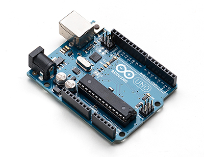
Here's what the Arduino looks like (this is the Uno version)
IPB Image

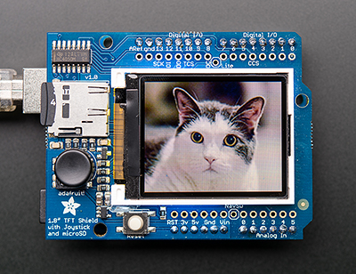
Here's the screen shield
IPB Image

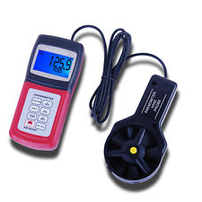
Here's the MAP sensors I'm going to start with.
IPB Image

I'm also probably going to have to make some plates that will go between the carb and manifold with a vacuum port on it. This would be the easiest way to access manifold vacuum since I can't count on carbs to have vacuum ports. Oh, and this will also be useable while driving to evaluate dynamic synch.
stugray
If you are interested in Arduino, checkout sparkfun

I drive by their warehouse every morning. Let me know if you need any code help.
euro911
Click to view attachment

So, is this like a CAT scan for carbs? laugh.gif
McMark
av-943.gif
rick 918-S
Sound is how I used to tune my triple Holley's on my big block. I wonder if you can add a mic function with a oscilloscope type output to the screen as a veri-able. Ya, I have no clue what I'm purposing. screwy.gif wacko.gif blink.gif
pcar916
QUOTE(rick 918-S @ Oct 16 2013, 01:13 AM) *

Sound is how I used to tune my triple Holley's on my big block. I wonder if you can add a mic function with a oscilloscope type output to the screen as a veri-able. Ya, I have no clue what I'm purposing. screwy.gif wacko.gif blink.gif


This will be interesting to see if you can get all 4 or 6 outputs on the same screen. Or are you going to use a numerical index if the screen won't print nice lines?

The Arduino microcontroller works at 16MHz. I don't remember the video resolution on that shield's screen. If that shield can't keep up with all 4 or 6 simultaneously ...

If you used the Arduino and output the screen info to a Raspberry Pi (faster and HDMI video output) or BeagleBone (faster yet). Both are Linux single-boards. The RPi has the best video resolution by far.

Or you could remote into either of the Linux boards with JuiceSSH (or something like it) and get the output on your laptop/notebook. I've only used the Arduino for stepper/servo/motor control and basic inputs like temperature, vibration, joysticks etc, and never played with a screen output directly from the Arduino.

Very cool project on a really fun platform! Let us know.

Good Luck

The Arduino
914forme
QUOTE(McMark @ Oct 16 2013, 12:39 AM) *


I'm also probably going to have to make some plates that will go between the carb and manifold with a vacuum port on it. This would be the easiest way to access manifold vacuum since I can't count on carbs to have vacuum ports. Oh, and this will also be useable while driving to evaluate dynamic synch.


Small feeds or offices much like you do when using a single map and ITBs. It will be interesting. What ever happened to large water draw vacuum tubes. to measure balance?

Click to view attachment

The small tubes in this example means its extremely sensitive. Larger Tubes would cut down on the sensitivity. Also larger decrease accuracy a little. I had one of these once, worked great.

Don't get me wrong cool project, I just would rather spend my time and $$ doing other items that benefited my time and $$$. If its is just for your enjoyment then carry on.
JStroud
Sounds like a good idea, Surprised nothing like that already exists, carbs have been around awhile, and the better synced the better they run.
Putting a plate between the carb and manifold seems like it would work to get a vacuum port....but when cars come in to be tuned, you would have to put a plate under each carb first, seems like something that could clamp/attach to the top with a vacuum port would be more universal and easier to use on all cars, just a thought....what do I know....I hate carbs. shades.gif

Jeff
Matt Romanowski
Why do you feel the regular methods are not accurate enough?
jaxdream
I say go for it !!! You seem to be always looking to come up with something usefull and incorparating some of the latest technology , heck if this stuff was around when the idea of measured data started to be used ,THEY would have used it . Nothing ventured , nothing gained . Perhaps some kind of vacum resiviour for the MAP sensors to eliviate the pulses , or a vacum check valve . Experiment away to your heart's desire (or wallet ) !!!! piratenanner.gif aktion035.gif

Jack
SirAndy
QUOTE(McMark @ Oct 15 2013, 09:39 PM) *
Some sort of averaging could help. idea.gif

If you need some help with that let me know, we do that sort of thing on a daily basis.

Besides just averaging out your samples you also want to throw away your high and low spikes.

Just don't trow away your good data if you are oscillating between high and low.
shades.gif
McMark
QUOTE(pcar916 @ Oct 16 2013, 06:50 AM) *
This will be interesting to see if you can get all 4 or 6 outputs on the same screen. Or are you going to use a numerical index if the screen won't print nice lines?

The Arduino microcontroller works at 16MHz. I don't remember the video resolution on that shield's screen. If that shield can't keep up with all 4 or 6 simultaneously ...
I'll have to deal with this as it comes up. Not worth speculating. There also may be some old school efficiency tricks out there as well. Once upon a time coders had to be really creative writing their code to optimize for the platform restrictions.

QUOTE(914forme @ Oct 16 2013, 06:50 AM) *
What ever happened to large water draw vacuum tubes. to measure balance?

Don't get me wrong cool project, I just would rather spend my time and $$ doing other items that benefited my time and $$$. If its is just for your enjoyment then carry on.
I have one of those I've never used because it's so impractical. I'm sure it would work just fine, but I'm hoping for something that can be used while driving as well.

QUOTE(jsconst @ Oct 16 2013, 06:51 AM) *
Putting a plate between the carb and manifold seems like it would work to get a vacuum port....but when cars come in to be tuned, you would have to put a plate under each carb first,
That's the idea. I very often weld in O2 sensor bungs on cars that come in. Installing plates permanently underneath the carbs would be my approach. I could even make them out of some phenolic material to help with heat transfer.

QUOTE(Matt Romanowski @ Oct 16 2013, 08:12 AM) *
Why do you feel the regular methods are not accurate enough?
I guess to be clear, they are accurate enough but again, this info can't be assessed while driving.

QUOTE(SirAndy @ Oct 16 2013, 10:23 AM) *
If you need some help with that let me know, we do that sort of thing on a daily basis.
Will do. I'm planning on keeping this thread up to date including code. I know we have a lot of coders here and I'm looking at this as a bit of an open source project. Hopefully with more eyes the code can evolve in efficiency and accuracy.
OU8AVW
Your set up is real nice, but I'm way ahead of you....

ADMIN EDIT: Yer boobs belong to the Sandbox!
Harpo
Nice and I'm not even in the sand box!
bfrymire
This looks like fun. Couple of comments. I think that a flow meter would work much better rather than a MAP sensor. I did a quick search and could not find the ones i have encountered before. So, I looked at MAFs, which were way too expensive.

Hum. Well, all a MAF is, is a wire heated to temperature and as air flows over it, the temperature of the wire fluctuates and hence its resistance. So, if you used the Arduino ADCs to measure a voltage across the wire, you could sense the air flow. So, it is possible to build your own MAF. Just a thought.

As far as averaging, you have to determine the type of signal you are trying to measure. Signals will have a low frequncy content (Usually what you are trying to measure) and a high frequency content (noise in this case.) Well, if you use standard averaging, you will get a flat line response and loose all of the low frequency content, such as air flow fluctuation. However, using box car averaging you will get some noise rejection, and still retain the low frequency content.

Have you thought about how to display to data to make it easy to adjust? This is me is similar to leveling signals, so, I have used a contour plot to display the data and put a "leveling bubble" on it to represent the center of all four corners, and then you adjust to "bubble" to center. Again, just a thought.

BUt, it sure looks like fun!

-- brett
Mike Bellis
QUOTE(bfrymire @ Oct 16 2013, 06:40 PM) *

This looks like fun. Couple of comments. I think that a flow meter would work much better rather than a MAP sensor. I did a quick search and could not find the ones i have encountered before. So, I looked at MAFs, which were way too expensive.

Hum. Well, all a MAF is, is a wire heated to temperature and as air flows over it, the temperature of the wire fluctuates and hence its resistance. So, if you used the Arduino ADCs to measure a voltage across the wire, you could sense the air flow. So, it is possible to build your own MAF. Just a thought.

As far as averaging, you have to determine the type of signal you are trying to measure. Signals will have a low frequncy content (Usually what you are trying to measure) and a high frequency content (noise in this case.) Well, if you use standard averaging, you will get a flat line response and loose all of the low frequency content, such as air flow fluctuation. However, using box car averaging you will get some noise rejection, and still retain the low frequency content.

Have you thought about how to display to data to make it easy to adjust? This is me is similar to leveling signals, so, I have used a contour plot to display the data and put a "leveling bubble" on it to represent the center of all four corners, and then you adjust to "bubble" to center. Again, just a thought.

BUt, it sure looks like fun!

-- brett

agree.gif
with the MAF's. This way you could see flow at high rpm too. A MAP will loose signal off idle unless it is a pressurized system. VW/Bosch (type) MAF's are pretty cheap and are voltage based. GM MAF's are frequency based if you want to go that route.
stugray
You dont need to overthink this one.

Since these are not being used to measure an absolute value for flow (like used in FI), but a relative flow between cylinders.

As long as the sensors are all mounted the same and calibrated simultaneously for the no-flow case (atmospheric pressure for baseline), they should work well for showing balance between cylinders with fairly simple averaging.

If you need fancy, then a "simple" Kalman Filter would be fun
McMark
QUOTE
A MAP will loose signal off idle unless it is a pressurized system.
They don't lose signal. They only drop to "zero" at WOT. But even then if there were a difference you would see different values close to "zero".

McMark
Started working on this project this weekend. Got the board soldered, ran the test code to make sure it worked, then started working out the layout. Runs pretty fast and seems like it'll work well.

This is just with random values.

https://www.youtube.com/watch?v=3pBbAG4x0P0


Now I need to start working on averaging. Feel free to post detailed averaging formula/code/links.
bulitt
Another alternative -purchase a used flow bench (small for motorcyle heads), or buy this flowquick from Audietech.com and build a bench with a vacuum motor. You would probably have to remove each carb to test on the bench though.


Nice!-
IPB Image
ww914
I love gauges. The more the merrier, but I m running out of room. Good work Mark!

Click to view attachment
McMark
headbang.gif

I can't believe I'm still getting the 'use the tube and water method' posts. I thought I was pretty clear. I'm not asking how to sync carbs. I'm sharing my project that I've already decided to build and am nearly halfway done with. rolleyes.gif

From Post #12
QUOTE
I have one of those I've never used because it's so impractical. I'm sure it would work just fine, but I'm hoping for something that can be used while driving as well.
euro911
Stick to your guns, Mark aktion035.gif
ConeDodger
QUOTE(McMark @ Nov 17 2013, 08:33 AM) *

headbang.gif

I can't believe I'm still getting the 'use the tube and water method' posts. I thought I was pretty clear. I'm not asking how to sync carbs. I'm sharing my project that I've already decided to build and am nearly halfway done with. rolleyes.gif

From Post #12
QUOTE
I have one of those I've never used because it's so impractical. I'm sure it would work just fine, but I'm hoping for something that can be used while driving as well.


For the record, Mark has one of those tube and water methods leaning against the wall. He's been there, done that... dry.gif
SirAndy
QUOTE(McMark @ Nov 17 2013, 08:33 AM) *
I can't believe I'm still getting the 'use the tube and water method' posts.

Can't you just sprinkle some water on your circuit board? That should work ...
rolleyes.gif
gothspeed
QUOTE(McMark @ Nov 16 2013, 09:28 PM) *

Started working on this project this weekend. Got the board soldered, ran the test code to make sure it worked, then started working out the layout. Runs pretty fast and seems like it'll work well.

This is just with random values.

https://www.youtube.com/watch?v=3pBbAG4x0P0


Now I need to start working on averaging. Feel free to post detailed averaging formula/code/links.

This is a great idea McMark smilie_pokal.gif ! It would be useful for any engine using individual butterflies per cylinder or per cylinder bank not just carbs smile.gif.

I currently use individual vacuum gauges for each cylinder but I know there is some variation to each of the bellows inside of each gauge. So something like this should theoretically have less variation. What do you think the price point would be on a 4 channel sensor system? idea.gif
02loftsmoor
I used Mercury Sticks to balance my Motor cycle carbs works great.. it's only about 24" long
r_towle
Cool project.
To bad the sensors are so large...
Would be nice to have the whole system hidden.
ConeDodger
QUOTE(r_towle @ Nov 17 2013, 08:00 PM) *

Cool project.
To bad the sensors are so large...
Would be nice to have the whole system hidden.


He plans on hiding it in a tool cabinet. Tuning tool... smile.gif
Dave_Darling
I'm still really liking Mike B's idea of using multiple air-flow meters...

--DD
gothspeed
QUOTE(ww914 @ Nov 17 2013, 07:00 AM) *

I love gauges. The more the merrier, but I m running out of room. Good work Mark!

Click to view attachment

Are those 4 temp readings air intake temps?
Andyrew
That is awesome! Would be great for bikes... Hard to do many things at once, especially with 4 carbs..
McMark
QUOTE(r_towle @ Nov 17 2013, 08:00 PM) *

Cool project.
To bad the sensors are so large...
Would be nice to have the whole system hidden.

I found small sensors I'm going to try.
Not my hands. icon8.gif
r_towle
Can you use an airflow sensor for what you are doing?
At the end of the day, it's a wire suspended across a tube/cylinder.
Seems you could cut that down to an inch or less in height..
Or incorporate it into a velocity stack.

I do love the idea...
Spoke
Looks pretty cool.

We've used Arduino for several projects. I did an interface board to Arduino for a customer.

Let me know if you need any help with a design or a PCB.
ww914
QUOTE
Are those 4 temp readings air intake temps?
No they are aircraft cylinder head temps gauges with a sensor under each spark plug. This is an old photo. I now have an oil temp gauge as well on the bottom. Sorry, I messed this post up.
stugray
Mark,

I thought about another excellent use for your arduino project:

http://www.arduino.cc/en/Tutorial/KnockSensor

&

http://www.ebay.com/itm/E46-bmw-m3-s54-kno...093&vxp=mtr

Your arduino should have 6 Analog inputs.
SO you should have two left.
You could put one knock sensor on each head.

I am also playing with a arduino that could be used for variable ignition timing. It would have a programmable advance curve based on RPM.
Then you could make it change timing based on:RPM Manifold pressure (load) and input air temperature.
If you had the knock sensor, it could retard timing if knock is detected.
AE354803
QUOTE(McMark @ Nov 17 2013, 09:15 PM) *

QUOTE(r_towle @ Nov 17 2013, 08:00 PM) *

Cool project.
To bad the sensors are so large...
Would be nice to have the whole system hidden.

I found small sensors I'm going to try.
Not my hands. icon8.gif


Nice project. I'm surprised how well it is reading the individual vacuum pulses.

Just a thought, if you are having issues with filtering/averaging the vacuum waveform into a stable value, adding a length of tubing between the manifold and the sensors should help equalize the pulse, especially if there is a reservoir of some sort in that line.
jfort
interesting. and I had as a winter project an attempt to tune the Webers on my six. Now I think I should wait and watch this thread.
McMark
Haven't had a carb'd car in to do any more testing with it. I added some filtering by throwing out values that are some percentage different than the last 'real' value. So it would basically limit the indication from moving beyond a relatively small range.

I really need a daily driver with carbs on it to really test this out.
Dr Evil
Liking this a lot smile.gif popcorn[1].gif

I am with the MAF idea. Place on the stacks, cut to fit length.
bulitt
I agree, this Arduino stuff is a cool concept.
Read where some MAF's output acceptable voltage for the Arduino.

I understand your quest to learn and build a tuning tool, for the rest of us not so technically gifted-
How about an airflow anemometer (@ 48$ on Ebay). Slip it over the carb somehow. It reads air velocity, but more importantly CFM.

IPB Image
biosurfer1
QUOTE(McMark @ Feb 10 2014, 02:52 PM) *

I really need a daily driver with carbs on it to really test this out.


I'd love for you to use my car as much as you'd like to test this out. I'm pretty sure my carb's are way out of whack anyways.
McMark
Brett, sounds like a good plan. I'll get two more sensors set up and then get in touch. Then you can come down and we'll install it semi-permanently. Do some testing and then you can keep it in your car and we'll upgrade the code over time.

It's not doing any good here on my desk. wink.gif
McMark
QUOTE(bulitt @ Feb 11 2014, 06:34 AM) *

I agree, this Arduino stuff is a cool concept.
Read where some MAF's output acceptable voltage for the Arduino.

I understand your quest to learn and build a tuning tool, for the rest of us not so technically gifted-
How about an airflow anemometer (@ 48$ on Ebay). Slip it over the carb somehow. It reads air velocity, but more importantly CFM.

IPB Image

It might work. Only one way to find out. wink.gif
This CFM reading is essentially what the 'snail' Synchrometer does, so it should work just fine and your idea will give you a numeric reading whereas the Synchrometer is much more ambiguous.
ClayPerrine
QUOTE(McMark @ Feb 11 2014, 10:19 AM) *

QUOTE(bulitt @ Feb 11 2014, 06:34 AM) *

I agree, this Arduino stuff is a cool concept.
Read where some MAF's output acceptable voltage for the Arduino.

I understand your quest to learn and build a tuning tool, for the rest of us not so technically gifted-
How about an airflow anemometer (@ 48$ on Ebay). Slip it over the carb somehow. It reads air velocity, but more importantly CFM.

IPB Image

It might work. Only one way to find out. wink.gif
This CFM reading is essentially what the 'snail' Synchrometer does, so it should work just fine and your idea will give you a numeric reading whereas the Synchrometer is much more ambiguous.


One problem with that...... the reversion caused by a big, lumpy cam will cause backflow pulses. And that will foul up a fan type anemometer the same way a big cam fouls up L-jet injection. You need a hot wire type anemometer. and those are about 500 bucks.
Dr Evil
Junk yard MAF not an option? I bet you find 4-6 of the same model and get them for about $30 ea
McMark
Not for me. At least at this time. I've picked my path and I'm gonna see it through until I get something I consider a working setup. Then I may move on to MAF. But MAP is so much easier to set up in the car and I can't imagine how to make a MAF setup that even comes close to that simplicity.

Although, maybe if I built the MAF into a package that would bolt onto the top of the carbs in place of an air cleaner... idea.gif
bulitt
QUOTE(ClayPerrine @ Feb 11 2014, 11:29 AM) *

QUOTE(McMark @ Feb 11 2014, 10:19 AM) *

QUOTE(bulitt @ Feb 11 2014, 06:34 AM) *

I agree, this Arduino stuff is a cool concept.
Read where some MAF's output acceptable voltage for the Arduino.

I understand your quest to learn and build a tuning tool, for the rest of us not so technically gifted-
How about an airflow anemometer (@ 48$ on Ebay). Slip it over the carb somehow. It reads air velocity, but more importantly CFM.

IPB Image

It might work. Only one way to find out. wink.gif
This CFM reading is essentially what the 'snail' Synchrometer does, so it should work just fine and your idea will give you a numeric reading whereas the Synchrometer is much more ambiguous.


One problem with that...... the reversion caused by a big, lumpy cam will cause backflow pulses. And that will foul up a fan type anemometer the same way a big cam fouls up L-jet injection. You need a hot wire type anemometer. and those are about 500 bucks.


I think I read these units take an "average" measurement so possibly the lumps would be smoothed out? Possibly inserting it into a pvc pipe about 18" from the carb may help ???

Now I am seeing "hot wire probe anemometers" on Ebay @230$ idea.gif
Dr Evil
QUOTE(McMark @ Feb 11 2014, 11:50 AM) *

Not for me. At least at this time. I've picked my path and I'm gonna see it through until I get something I consider a working setup. Then I may move on to MAF. But MAP is so much easier to set up in the car and I can't imagine how to make a MAF setup that even comes close to that simplicity.

Although, maybe if I built the MAF into a package that would bolt onto the top of the carbs in place of an air cleaner... idea.gif


That is what I envision. Either on tubes angles centrally from the carbs, or just sticking straight up on shorter stacks. I typed MAF and Bosche into ebay and found some deals among the new parts that are much more. I do respect the MAP approach as it is cheaper and stupid simple.
This is a "lo-fi" version of our main content. To view the full version with more information, formatting and images, please click here.
Invision Power Board © 2001-2024 Invision Power Services, Inc.