Help - Search - Members - Calendar
Full Version: 2270 Build thread
914World.com > The 914 Forums > 914World Garage
Pages: 1, 2
vjb206
Hey folks! I've got...
  • Case halves from an old 1.7 (cleaned as best I could)
  • 2270 crank + P&C kit
  • #163/86b Web Cam
  • 2.0 heads with 44X36 valves, where I'll be installing dual springs and 38mm exhaust valves
  • Upgraded oil pump and other goodies
So my first question for the community has to do with ensuring the rotating mass is spinning freely/correctly…

I started by measuring all of the the main journals on the crank and I got a range from 2.358” - 2.360” (I used a digital caliper and I'm pretty sure I did this correctly).

Then I “dry-fit” Silverline STD/STD main bearings into the case (sans crank), torqued everything down, and got 0.003” in radial play (I used a cylinder bore dial gauge for the first time, and I think I did it correctly).

The spec-sheet says radial play should be between 0.06” - 0.10” (0.03” - 0.09” for #2); and I have 0.003." I'm a MINIMUM of 0.057" off, is that normal? What's my next step?
  1. Stop pretending I know what I'm doing and take it to a machinist for test-fitting and honing (I'd like to keep cost down so this is my less preferred option)
  2. DIY: hone 0.06" off all bearings (what's the right honing tool / approach here?)
  3. Order different bearings (if so, which?)
930cabman
Did you get the rotating components balanced?

Not sure of "radial" are you meaning axial? crankshaft end float?

I generally assemble the case/bearings/crank/plasti gage, torque every down and disassemble and read the plasti gage

Are all the oil passages clean, really clean

Sounds like she will be a great build
Superhawk996
Hopefully this doesn’t come off as condescending - that is not my intent .

Slow down - you’re not ready to do that build yourself based on what you’ve written and the questions you’re asking.

I’m not saying you can’t do it. Just that you’re not ready.

Read Tom Wilson book. Watch Raby DVD. Keep asking questions.

1st - Don’t measure crank journals with a caliper. It doesn’t have the accuracy and repeatability for the job. A Micrometer is the proper tool, is repeatable, and is 10 times more accurate than a caliper. You shouldn’t be getting a variance of 0.002” when measuring journals. Not within a single journal nor .002” across all journals. If you had .002” of variance across journals - the crank would need to be reground in order to get proper bearing clearance.

Sanity check: rule of thumb for automotive main bearing clearance is 0.001” per inch of journal diameter. So about 0.0024” - 0.0025” would be the expected target clearance based on that rule of thumb.

Edit: a digital caliper is only accurate to about .001” which is almost 1/2 of the target clearance. Not accurate enough for the job. A micrometer is accurate to about 0.0001”. This is the “why” behind the need to use a micrometer for journal measurements.

2nd - you are confusing bearing clearance with some other radial play measurement.

3rd - no automotive engine bearings are run with 0.06” - 0.1” of clearance. Not sure what the “spec sheet” is that you are referring to. Are you confusing specs between inches and millimeters? Post details of where you are getting info from and make sure it is correct information before proceeding.

I would suggest having machinist confirm measurements if you don’t have proper tools.

4th - any talk of honing bearings and what tool to use is crazy talk.

Slow down - learn more. Props for coming here with the questions before doing anything rash. beerchug.gif

You’ll find help and lots of folks here willing to help you succeed. I’ll apologize in advance if it seems I’m being harsh and not trying to help.
Montreal914
To measure the crank, I would use a micrometer, not a caliper.

You will want to check the cylinder spigot on the case for flatness (they get hammered down). You want to check everything on that case and do the galley plugs. You will want to check your oil pump fit too, and the interference with the cam shaft, but you probably know that and aren't there yet. Be prepared to dry fit open and close that case many times.

With your case torqued on your bearings, check to make sure the case halves are actually closed using a back light. On my 2056 assembly, when I did that step, I could see light between the two halves. The bearing halves were in contact, but not the case.

I doubt you can do the line bore without the proper boring bar and the milling that will allow you this setup.

Obviously many more verification steps to come, but the case, line bore, spigot flatness, spigot distance to center line, etc...

Rod interference check is another important one. Rods to case depending which rod you are using. Also rod to cam.

Van Svenson has nice videos on his build including issues he had. There used to be a website with his step by step process but the link seems to be broken. If someone has it, please share it. smile.gif

This was it: http://www.ephotomotion.com/914engine/

Share your progress! smile.gif

vjb206
Great responses! Thank you for the engagement.

@930cabman
  • Balancing is next, as I'd like to know if I need to take material off of anything before taking it back to the machinist. I will not balance myself.
  • I hope the oil passages are clean - I did have a machinist clean the case halves. They're not as clean as I've had done in the past because, evidently, the "good stuff" caustic solutions aren't allowed in NJ any more. ¯\_(ツ)_/¯

@Superhawk996 :
  • I have Jake's DVD and have watched it several times, he doesn't cover bearing play/tolerances.
  • "Crank journal measurement should not have variance in the thousandths." Got it! I will re-measure with a mechanical outside micrometer. I just happen to have a digital caliper so I started there.
  • "about 0.0024” - 0.0025” would be the expected target clearance." This is more like what I measured! Thank you for the gut-check there. Once I re-measure the crank mains with a micrometer, I'll re-measure the torqued case with the cylinder bore dial gauge to re-verify (Side-bar: that central groove in the middle of the bearings sure makes it hard to rock the bore dial gauge back-and-forth without catching).
  • As for my spec-sheet, it's my fault for trusting the internet... It was from this thread a while back: http://www.914world.com/bbs2/index.php?showtopic=191442 You can see the "radial play" under the "crankshaft and connecting rods" section. The numbers are from there. I guess that image looked legit and I just assumed it was accurate. Thanks for setting me straight.

@Montreal914 :
  • Case halves were rubber-mallet-hammered and through-bolts torqued to 25 ft. lbs. No daylight, so I think I'm good there.
  • I'm not checking line bore yet. I'm just making sure my clearances are correct. One I assemble with the crank I'll check for binding on the rotation to indicate the need for a line bore.
  • Thanks for the link! Doesn't work for me but I'll check back.

To all: THANK YOU SO MUCH. I've been reading this forum for a while trying to self-educate, but there's nothing like posting and receiving several responses within minutes. You all rock.
Montreal914
Van Svenson still has his YouTube videos on his channel though. But the written document was nice to follow. Tried reaching him on Hackracing.com but the mail bounced back… sad.gif
I’d like to have that written reference blog/text.
Superhawk996
Regarding info in the link you provided - all those measurements are in millimeters


.06 mm x .0394”/mm = .002364”. Suspiciously close to our rule of thumb target clearance.
vjb206
Measurements are in MM. Excuse me while I––––

IPB Image
Superhawk996
QUOTE(vjb206 @ Dec 11 2023, 01:21 PM) *

Measurements are in MM. Excuse me while I––––

IPB Image


lol-2.gif Trust me I've done that too. Just gotta' be sure you know what the spec is and how its measured.

Here's a tip: If the measurement is only two significant digits (.06) it's probably in metric. Three or Four significant digits (.024 or .02364) is probably inches. This is because a miilimeter is such a small fraction of an inch, it only takes two significant digits to get you into very small numbers with high precision.
930cabman
hate to ask, but have you built engines in the past?

There are many things going on with the guts and it's easy to make a mess, especially with all the cool parts you have.
rhodyguy
I did not note this in the intro. Remove, tap and replace galley plugs (excellent op to get clean passage ways ultra clean), ensure align bore is not required, ensure the case halves don't need decking. What is the plan to feed this engine?
rhodyguy
Admin delete please.
914sgofast2
I would suggest you read the post named "Cheap, Junk rebuild" over on the Samba.com in the 411/412 forum or over on the Type4Forum websites, if you haven't done so already. He goes through the entire rebuild on a budget process in great detail and tells you where to save money and where to spend money when rebuilding a Type 4 engine. He has an excellent tutorial on how to properly clean your engine case with commonly available soaps and degreasing agents, as well as how to clean all the oil galleries and install new oil gallery plugs. It sounds like you are building a high performance engine and you need to do the best job you can. I just saw on the "4th Dimension Type 4 Porsche/VW Performance" Facebook page for high performance Type 4 engines that Jake Raby is going to be giving several classes online on how to build a high performance Type 4 engine using his tips and tricks at a very affordable price next year.
technicalninja
QUOTE(914sgofast2 @ Dec 11 2023, 01:08 PM) *

I would suggest you read the post named "Cheap, Junk rebuild" over on the Samba.com in the 411/412 forum or over on the Type4Forum websites, if you haven't done so already. He goes through the entire rebuild on a budget process in great detail and tells you where to save money and where to spend money when rebuilding a Type 4 engine. He has an excellent tutorial on how to properly clean your engine case with commonly available soaps and degreasing agents, as well as how to clean all the oil galleries and install new oil gallery plugs. It sounds like you are building a high performance engine and you need to do the best job you can. I just saw on the "4th Dimension Type 4 Porsche/VW Performance" Facebook page for high performance Type 4 engines that Jake Raby is going to be giving several classes online on how to build a high performance Type 4 engine using his tips and tricks at a very affordable price next year.


That is the type of information that makes looking at ALL the posts worth it...

To the OP.
I know what I'm doing...
I've been building standard and high-performance motors all of my professional life.
I'll be wrenching a week before I die...

That's GOLD!

I'll be looking into that.

Thanks for posting that tidbit. first.gif first.gif
vjb206
QUOTE(vjb206 @ Dec 11 2023, 01:21 PM) *

Measurements are in MM. Excuse me while I––––

IPB Image

lol-2.gif Trust me I've done that too. Just gotta' be sure you know what the spec is and how its measured.

Here's a tip: If the measurement is only two significant digits (.06) it's probably in metric. Three or Four significant digits (.024 or .02364) is probably inches. This is because a miilimeter is such a small fraction of an inch, it only takes two significant digits to get you into very small numbers with high precision.


Hey folks - Merry Christmas and a Happy New Year! I'm back at measuring and have some more accurate figures (see below on method). Bottom-line is that for all of the bearings I have either zero clearance (like literally 0.00mm radial play), or at most I have 0.03mm.

IPB Image

Bearings as follows:
  • #1: 0.01mm radial play
  • #2: 0.03mm radial play
  • #3: 0.00mm radial play
  • #4: 0.00mm radial play

@Superhawk996 , @Montreal914 , @930cabman : Assuming this is normal, my next step will be to call my friendly neighborhood machinist to take the required amount of material off each bearing so that the tolerance sits on the low end of the radial play spec. Does this sound right to you?

Thanks for everyone's input so far, I truly appreciate it.

///// Process /////
  1. Measure main journals. They all came in on-spec: #1=59.98mm, #2=59.99mm, #3=59.98mm, #4=39.95mm. Call this A
  2. Set bore dial gauge to nearest constant. Mine worked out to be 61.13mm. Call this C
  3. Dry fit bearings and torque case
  4. Measure how far "in" the dial bore gauge measured for each of the bearings. Call this D
  5. Radial play for each was (C-D)-A
  6. Note: For #4 my dial bore gauge didn't fit (was too big even at its smallest setting), so I didn't get torqued figures, but it all came out to 0.00mm play so ¯\_(ツ)_/¯


technicalninja
I'm a big believer when making a "comparison" measurement try to keep all of the readings on a single tool.

here's how to do bearing to journal comparisons the normal way.

Bearings installed in block dry, torqued up.
Use "snap expanding" gauge set to find inner diameter. You have to be stupid centered and straight. Lock gauge. Measure with micrometer. Measure crank journal with same micrometer.

Even if you have a low-quality tool the difference between the two readings on that singular tool will be more accurate than using both a dial indicator and a micrometer together any day.

How to do it with a floating bore gauge: Mic crank, lock mic. carefully affix in vice and zero dial indicator to the micrometer. You have now zeroed your dial indicator to the crank journal and what you read inside the bearings bores is your actual clearance.

Both methods are using a single tool to actually take the measurement.

Hope this helps.

Never in my life have I had to have a set of main/rod bearings honed to size.
I've used specific +/- .00025 stuff to blueprint.
I'm hunting tenths at that point. PIA!

You're way off IMO. Too far off for a bearing screw up.

Try different techniques.

I wouldn't take that to the machine shop yet...


mepstein
“: Assuming this is normal, my next step will be to call my friendly neighborhood machinist to take the required amount of material off each bearing so that the tolerance sits on the low end of the radial play spec. Does this sound right to you?“

Hell No
technicalninja
I'd also convert everything to US standard instead of metric.

You might create chaos with a machine shop here in the USA.

Automotive Machine, a shop I use, specialized in air-cooled VW stuff first, has NEVER given me a reading back in metric...

They're making oil field equipment out of Type1s now...


https://www.automotivemachine.com/
Superhawk996
Yeah - hit pause. Something is wacko - probably measurements.

Technicalninja’s technique suggestion is good to minimize error swapping back and forth between devices.

There is also an aspect of these methods (snap gauges, dial indicator bore gage) that is overkill. The main reason to use gauges like you are is to determine roundness of the main bearing bore.

At this stage in the game - let’s just focus on bearing clearance.

Since you have all parts, you can use Plastigage. Plastigauge is a more direct measurement and avoids the math and multiple gage use issues.This method will give you a good rationality check on the math you’ve done. Plastigage will measure clearance very precisely but won’t tell you much about roundness. For now, that’s fine.

I’m not going to spell out the whole process to plastigage parts here. Google and YouTube will fill in the details. Get a couple strips each of Plastigage in red and green from your local flaps. The only trick to using Plastigage is to make sure the crank doesn’t move while you’re tightening the case or re-splitting the case. If the crank moves, it will smear the Plastigage and you’ll get an erroneous measurement. Overall, a much simpler, direct way of measuring bearing clearance.

Green =.001” - .003”
Red = .002” - .006”

This will cover any plausible range of clearances you should be playing with. If you truly have zero clearance, you’ll squish out the green to a width way wider than the .001” marking on the paper package / gage.

Under no circumstance will you ever hone a T4 bearing to size.
Superhawk996
Also I want to take a second and commend you for learning how to do this. Don’t want these posts to come off as any sort of chastisement.

Learning to use micrometers and snap gages takes time to use them accurately and repeatably. There is a great deal of “feel” to it. You have to have the same feel for each measurement. Otherwise, you can easily be off 0.0005” when using micrometers. Snap gauges even more so. As Ninja said, the snap gage has to be held perpendicular to the bore and can’t be bumped while you lock it or while you remove it from the bore.

Dial bore gages seem easy to use but again as Ninja outlined, you have to have a solid process to “master” to otherwise you’re just adding measurement error.

You are playing in the deep end of the pool and maybe just treading water at the moment. Don’t give up. Keep measuring, learning, and compare results against Plastigage. You’ll be swimming soon!

aktion035.gif
technicalninja
agree.gif agree.gif agree.gif agree.gif agree.gif


SuperHawk gives good advice.

I, too, use Plasti-gauge in EVERY SINGLE BUILD.

I do all the mic measuring, math, the freaking hard way FIRST.

I then (should!) know what my clearances are to the fourth decimal point.

I'm BAD-ASSED at this...

I then use the Plasti-gauge as a "quality control check".

I'm backing myself up with a completely different way of taking the same measurement!

If the Plasti-gauge show different than what I expected I'm a HONKED DONKEY!

Complete re-check from the start to see where I made a FATAL mistake...
Self-flagellate as required.


One SUPER important tip regarding Plasti-gauge!

As it ages it shrinks FAST.

6 months down the line it's not very accurate and it's useless at 1 year.

With time it will shrink down to sewing string width...

I know this from personal experience.


Buy brand new Plasti-gauge only!

I worry "how long has that been siitting on the parts house shelf" so I always buy from a mass retailer. Summit is my go-to for PG.
It always looks new and fat...

Lots of techs and machine shops have negative experience with PG and it's a bit like POR15, either you like it, or you don't. I'm betting most of the "failed when used" troubles are more self-generated than a defect in the product.

It shouldn't be used alone in my book but it's a part of it all.


cgnj
I built my motor in around y2k. The choices were VW or Buick rod journals, VW length rods.

I find it hard to believe that you have standard size main bearing journals on your crank. A German crank would typically be the first oversize. Is it Chinese? I would be running that over to the machine shop to be measured and magnafluxed. I just paid about $100 for that service.

I saw a video of the process that EMS uses to check line bore. They check with the cam in a cam installed. I assume it would be the same to check the main bearings

Get you case decked. If you find someone on the East Coats without an 8 week backlog, please share.

1163/86b with duals. The springs will have to be checked for coil bind. Typically, they will have to relieve the bosses so you can fit dual springs and cut a small relief so you can get the lift without coil bind.

If you have Cr moly h beam rods, 3/8 bolts may clear the cam lobes, otherwise you will be relieving the end caps and shortening the bolts.

If you are running a Shadek oil pump measure the bore. It is typically undersized. CB performance pump is right in the middle of the spec.

I ran my motor for a while with HEs and a Triad exhaust. You will need headers.

Buy stroker pushrod tubes. I ran stock with spacers. I always had weeping.

Don't buy cylinder shims till your heads are done. I used JE pistons. They stuck out of my Jugs. Plus my chamber volume was only 54cc's so it to a while to get that sorted.

Balance everything.


Good luck
vjb206
Again, really, really great advice. Thank you @technicalninja , @Superhawk996 , and @cgnj

I went to my FLAPS and picked up PG. Since I'm checking the mains I needed to thread it in between the crank and the bearings (on all but #2 obvi) but I couldn't get it to go through without breaking. Perhaps there's some trick to "par-flatten" it just enough to get it in between the mating parts, but I couldn't do it.

So I called my local machinist and he said that he wouldn't take any material off the crank because it's chromoly and it'll lose some sort of protective coating. He told me to call the folks I got the parts from (AA Pistons).

Then I called AA and spoke to a very helpful person on the phone and he reassured me that the STD/STD Silverlines are the right bearings for the crank in the 2270 kit. He recommended I wet-fit it and "feel" if it spun freely and/or if there were any binding spots.

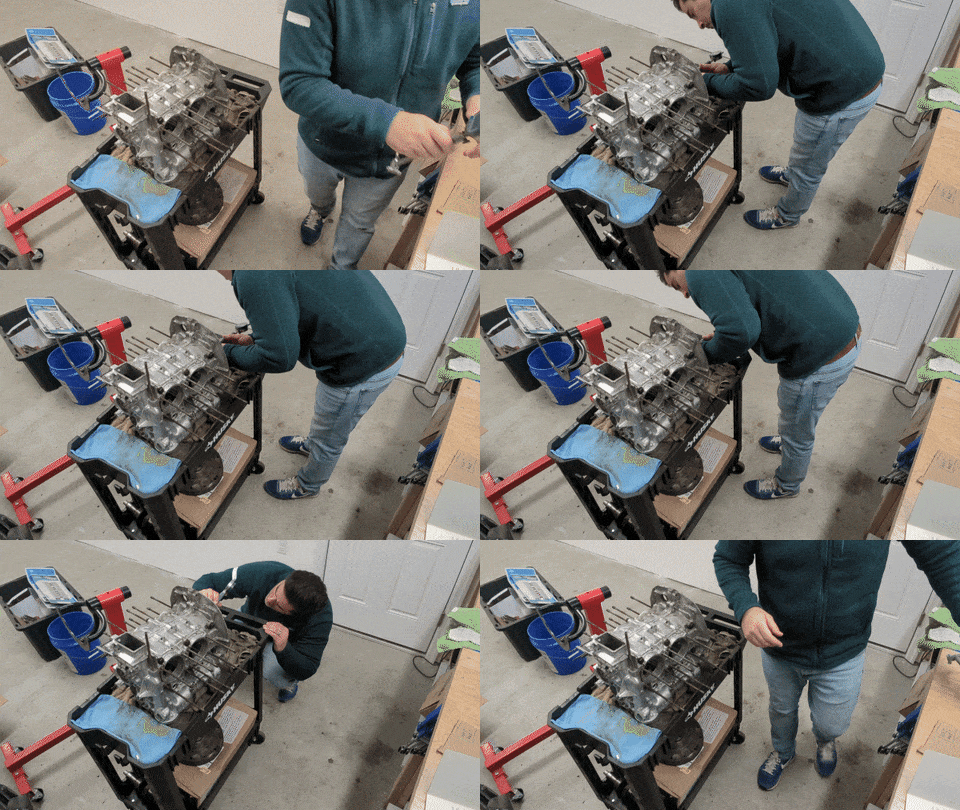
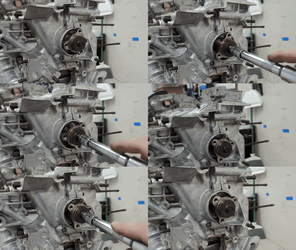
So.... I just did a wet fit and stopped futzing about ¯\_(ツ)_/¯

Here's the result:
IPB Image

I mean... the darn thing spins that's for sure. I still have no idea whether I need to do anything to the crank/bearings/line bore/etc. since I don't have reliable measurements to backstop me.

FWIW my machinist really doesn't want to be bothered with this job so perhaps I'll call around for someone how does? I did want to do this myself (and learn in the process), but I'm just not sure what my next step is other than to send it and hope.
technicalninja
Google search "how to properly use Plasti-gauge.

You're doing it wrong...
technicalninja
I have maybe a better suggestion for you right now.

Halt your build.

Educate yourself.

Purchase a type 4 rebuild manual. I don't know which one's best but someone else might chime in with good suggestions for "reading material".

Watch ALL of Ian Karrs videos.

I haven't watched them all. I don't need them nearly as much as the next guy due to my experience base but, the ones I have watched are GREAT. Very detailed in a manner that a novice can easily understand.

Watch them TWICE. Subscribe to his channel! Thank him profusely if they help.

I think they will...

Others are going to come up with more suggestions.

They may know better than me! Listen to the suggestions.

PMB sells 2255 for 16K!
Raby sells then for much more.
The parts themselves are really not that expensive. It's the experience that is required to make those not only run but run for years/decades that is the expensive part.

These cannot be assembled like a modern GM LS engine kit.

You are starting out your exploration into ICE engines on an engine that is "finnicky" to build and most of the aftermarket parts require more than just simple assembly.

Right now, I would advise you to become more educated in the basics before spending bucks going to Raby's class.

When I decide I want to tackle an un-known to me skill I'll spend many nights searching the internet and self-educate to a point I can ask specific questions and hopefully I will have figured out which questions are important.

In college, a classmate came up and said, "Boy do I like having classes with you!"
As we were not close, I asked "WTF?"
He said "you will ask the questions that are on everyone's mind, you will pester and make the instructor explain stuff in far greater detail. It's AWESOME!"

To which I reply "I'm paying BIG money to have access to the instructor's brain. It's a bit like prostitution; I get access, they have to answer, and I lose money. You're paying too, but you don't partake..."
His answer "I'd be embarrassed!"
And mine "we are NEVER going to see each other again after college. I don't care what you think about me and, hopefully, you feel exactly the same."

Educate yourself!
Don't ever miss an opportunity for greater knowledge for appearance sake.

If I am allowed to interact with Jake (IE: ask questions) during his class he's going to remember me!

I wish "Vulcan mind meld" wasn't a fantasy...
Superhawk996
I should have been more clear. You can only use Plastigage on the split bearing.

However, it is pretty reasonable to use that single split bearing as a proxy for the others while still being able to use it as a double check to your measurements.

Here’s the problem with assuming a free spinning crank equals success, too much clearance is as bad as too little clearance. Too much clearance results in low oil pressure.

Since you assembled and spun it here’s what we do know. You don’t have a zero clearance condition as your 2nd set of measurements was indicating.

What to do next?

I’d suggest going back and learning how to get your bore gage, micrometer measurements to agree with what Plastigage indicates on the split bearing.

I’d also spend some time measuring and Plastigage’ing the connecting rods.

At this point it’s just time to assemble & disassemble parts. The opportunity to learn here being the primary goal. The secondary goal is that you should eventually be confident that you know what your bearing and rod clearances are.
Superhawk996
QUOTE(vjb206 @ Dec 28 2023, 05:52 PM) *


So I called my local machinist and he said that he wouldn't take any material off the crank because it's chromoly and it'll lose some sort of protective coating. He told me to call the folks I got the parts from (AA Pistons).


FWIW my machinist really doesn't want to be bothered with this job so perhaps I'll call around for someone how does? I did want to do this myself (and learn in the process), but I'm just not sure what my next step is other than to send it and hope.

Time to find a real machinist

chromoly cranks can be ground if needed. How exactly does he think it was made in the first place?

If the crank needs to be heat treated and / or nitrided that’s a whole different ballgame typical of Porsche 911 crankshafts but to say it cant be done is moronic and I wouldn’t trust that guy at all.

The fact that he doesn’t want to be bothered with the job of measuring - fitting doesn’t bode well for him either. I wouldn’t expect it to be done for free but that’s different than doesn’t want to be bothered. Jeesh! ar15.gif
cgnj
@vjb206

I don't know where you are getting your numbers. I attached the table from the factory manual.

I used Fonse Performance in Sicklerville. It was serendipitous. Father was old school VW engine builder. Jr did all my parts. I was able to watch and see most of the operations used for my heads and rods. They did the balancing. They are still open.
Here is a link Fonse

Tools you still need. Deck height plate, dial indicator with magnetic stand, adjustable pushrod tube micrometer.

What size rod journals are you using? If you are using 2.0 with 5/16 bolt you may not have to clear the cam lobes or the web on 4/2.

Factory bearing clearance
Click to view attachment
Superhawk996
Duplicate
Superhawk996
QUOTE(technicalninja @ Dec 28 2023, 07:53 PM) *


Purchase a type 4 rebuild manual. I don't know which one's best but someone else might chime in with good suggestions for "reading material".


Tom Wilson book was / is indispensable in the pre-internet era. It was what I learned from prior to my 1st T4 rebuild way back around 1989!!

Click to view attachment the
Eric_Ciampa
First time engine builder here. Building a 2270 and I am about at the same spot. Got most of the parts. Working on oil galley plugs and sending parts off for balancing. Was reading Tom Wilson’s book and came across this section on using plastigage.
technicalninja
That's the way...


Plasti-gauge can only be used on split bearings. The single piece bearings have to be measured.


It's HARD to properly torque up a rod without moving it.

The tiniest movement destroys the accuracy.

They missed some important tips.

Make your length of plasti-gauge that you're inserting in the journal slightly narrower than the bearing width. It's best to have .020" (.5mm) on either side of the strip or you will have a harder time cleaning the PG off of the bearing and the crank. The radius corners squish the piss out of plasti-gauge; try to keep it out of the corners.

It is IMPORTANT to carefully remove the plasti-gauge after testing completely.
I use soft rags, WD/40, alcohol, and a soft touch. The inner surface of an engine bearing is extremely soft. You can scratch it with your fingernail.
Don't damage this surface when cleaning.
Superhawk996
QUOTE(technicalninja @ Dec 29 2023, 03:45 AM) *

It's HARD to properly torque up a rod without moving it.

The tiniest movement destroys the accuracy.

@technicalninja

Much easier if done between centers where you can alllow the rod to sit against something to prevent inadvertent rotation on the journals. In this photo, I would allow the small end to rest on the ways which have cardboard on them to prevent damage to the rod while being torqued. Unfortunately I don’t have a photo in that position but I trust you get the jist of the setup.

Click to view attachment

Not a hint of smearing

Click to view attachment

When I did my first engine I didn’t have fancy tools. Just put crank on a soft surface to protect it (cardboard, shop towel, etc.). Assemble rod horizontally, while laying against bench top, again so the rod can’t rotate.

I’ve also had good luck doing it while case is mounted in engine stand, rods hanging down. Use something soft (wood dowel, cardboard, etc) to jamb the small end of the rod so it can’t rotate while torquing the fasteners.
technicalninja
@Superhawk996

I'm guessing you're like me and by the time the PG is being used we already know what our clearances will be...

Both you and I will always be able to overcome roadblocks in the technical world as we have the "gotta rip it apart" mental illness!
I've had it forever.
I'll have active projects in process when I die.
I'd bet you are similar.

And here's yet another shortcoming in the horizontally opposed engine design...

All my 4/6/8 cylinder builds that are not opposed are capable at PGing all bearings main and rod together with a single crankshaft install.

No blocking or limiting rotation needed on anything...

This is one of the reasons I advised the OP "stop and learn" as enough "T4s do it this way/everyone else does not" exist to be critical. The T4 is not really harder than others to rebuild, just has some "non-standard" strangeness to understand.

Today, with all the different oil pump diameters, I'll check my cases for proper oil pump bore/clearance as well as main and cam bores.
I've NEVER done that on ANYTHING else in my life!

If I have to have cases line bored, I'll request a specific oil pump bore diameter based on the oil pump I purchase. This is weird in my book...

Edit: WOW! that crank is dirty for taking measurements. I hope your cleaning off each individual journal before...
beerchug.gif
Front yard mechanic
Holy cow if Vbj listens to all this expert advice it will be 20 years before he gets to drive the thing not everyone is a premadona. I say build it fill it with oil and run the crap out of it confused24.gif
vjb206
Ok we're in business and you guys are to thank. @cgnj you're right, my "spec sheet" was bunk. @Superhawk996 I ordered the Tom Wilson book - will be here in a few days.

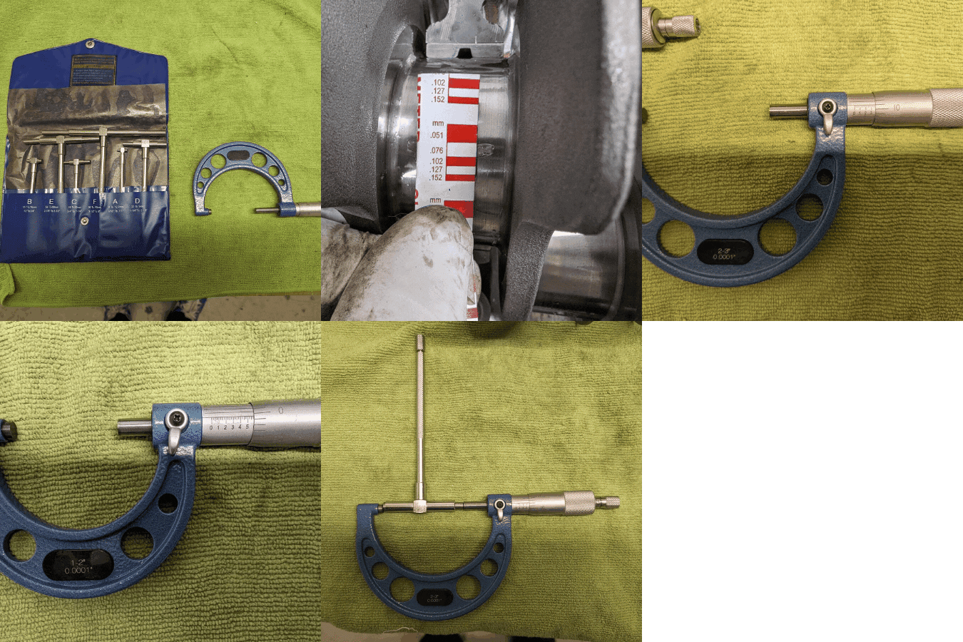
Today I went to HF (I know, I know) to pick up a set of micrometers and a telescoping gauge set. I measured the main journals, and #1 bearing torqued in the case (all I had time for). I also plastigage'd #2 with the case torqued to spec. And I'm definitely in the ballpark.

IPB Image

I got:
  • Main journals came in at 2.361" for #1-3 and 1.574" on #4, which is right on-spec
  • Plastigage on #2 came in at around 0.076 (or 0.0029") which is within the 0.0012" - 0.0035" spec that @cgnj posted
  • My telescoping gauge measured #1 just over 2.362" which represents a gap of just over 0.002" which, again, is within the spec @cgnj posted of 0.0016" - 0.0039"

So all-in-all today's gut-check felt good. Thank you all again.

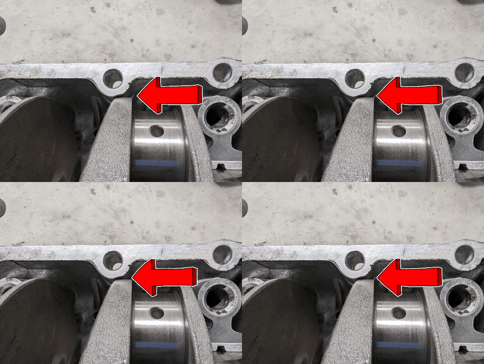
Also (I'll probably catch a lot of flak from you all on this) my stroker crank wasn't clearancing the case so I ground a bit of it off so that it clears ¯\_(ツ)_/¯

IPB Image

I'm going to spend more time this weekend measuring the clearances on #2, #3, and #4, as well as roundness on all bearings in the torqued case with my dial bore gauge.

Once the Tom Wilson book arrives, I'll have some light reading to occupy my time :-)

Next step: More measuring, reading, and finding a machinist for balancing the rotating assembly!
930cabman
Two comments, hoping you removed material from the case and not the crank to provide clearance and a machinist and a balancing tech are different skill sets generally not the same guy.
Superhawk996
smilie_pokal.gif

Congrats - while it’s apart don’t be afraid to play with the tools - all about feel.

Measure the same journal a couple times (no cheating by looking) by feel without watching the mic numbers. Write down the results. Get an idea of what your repeatability is.

Seriously - so glad it’s starting to make sense and that the numbers are plausible. aktion035.gif
technicalninja
Even today I'll make three distinct measurements for a "am I doing this right" check.

I have a set of the inexpensive snap gauges too.

I found a problem with mine.

As you tighten up the lock they tend to get slightly "looser" in the drag feel they produce.

I barely lock them to combat this. I trust them less than my bore indicator.

You might check if yours do the same.

Maybe it's just a glitch in my tools.

I lubed the piss out of my set. Ran them in and out.
It helped a little bit, but I don't trust mine...

The lasts set of numbers are decent. Keep practicing your measuring technique.

Massive improvement!
Superhawk996
QUOTE(technicalninja @ Dec 29 2023, 03:59 PM) *


And here's yet another shortcoming in the horizontally opposed engine design...

All my 4/6/8 cylinder builds that are not opposed are capable at PGing all bearings main and rod together with a single crankshaft install.

agree - those inline and V engines are weird. av-943.gif

Today, with all the different oil pump diameters, I'll check my cases for proper oil pump bore/clearance as well as main and cam bores.
I've NEVER done that on ANYTHING else in my life!

If I have to have cases line bored, I'll request a specific oil pump bore diameter based on the oil pump I purchase. This is weird in my book...

The oil pump OD size problem is due to using T1 parts in a T4 engine for which they were never intended. Using a T1 pump is just trading two flaws (size of pump OD & gears in single shear) for one T4 flaw (pump idler shaft migrates if engine is over heated). Personally, I’d rather address the single T4 pump flaw and pin the idler shaft. The engine shouldn’t be over heated in the 1st place but of course it can happen accidentally. Pinning the T4 idler shaft is cheap insurance. That’s my opinion and I’m sticking to it! shades.gif

Edit: WOW! that crank is dirty for taking measurements. I hope your cleaning off each individual journal before...

good eye! You’re seeing tool and die protector on the journals. This engine hasn’t been assembled yet so it has been doused in tool and die protector to make sure it doesn’t get any corrosion. That was cleaned off before measurements were made and reapplied after clearances were documented. aktion035.gif


@technicalninja
Superhawk996
QUOTE(Front yard mechanic @ Dec 29 2023, 09:02 PM) *

Holy cow if Vbj listens to all this expert advice it will be 20 years before he gets to drive the thing not everyone is a premadona. I say build it fill it with oil and run the crap out of it confused24.gif


idea.gif

Or . . . Don’t fill it with oil and run the crap out of it. Could end in the same result.

blowup.gif

stirthepot.gif laugh.gif
Montreal914
QUOTE(vjb206 @ Dec 29 2023, 05:26 PM) *

Next step: More measuring, reading, and finding a machinist for balancing the rotating assembly!


Looks like you case is good on the crank bearing side. Need to check its decking (cylinders seating surfaces). They get hammered in with time. Obviously needs to be perpendicular with crank axis and same distance from cylinder seating surface to crank axis. smile.gif
Jack Standz
QUOTE(technicalninja @ Dec 30 2023, 02:59 AM) *

@Superhawk996

I'm guessing you're like me and by the time the PG is being used we already know what our clearances will be...

Both you and I will always be able to overcome roadblocks in the technical world as we have the "gotta rip it apart" mental illness!
I've had it forever.
I'll have active projects in process when I die.
I'd bet you are similar.

And here's yet another shortcoming in the horizontally opposed engine design...

All my 4/6/8 cylinder builds that are not opposed are capable at PGing all bearings main and rod together with a single crankshaft install.

No blocking or limiting rotation needed on anything...

This is one of the reasons I advised the OP "stop and learn" as enough "T4s do it this way/everyone else does not" exist to be critical. The T4 is not really harder than others to rebuild, just has some "non-standard" strangeness to understand.

Today, with all the different oil pump diameters, I'll check my cases for proper oil pump bore/clearance as well as main and cam bores.
I've NEVER done that on ANYTHING else in my life!

If I have to have cases line bored, I'll request a specific oil pump bore diameter based on the oil pump I purchase. This is weird in my book...

Edit: WOW! that crank is dirty for taking measurements. I hope your cleaning off each individual journal before...
beerchug.gif


Yes, Type IV oil pumps are an area to spend some time on during any build project. The oil galley hole on a type 1 versus a type IV pump are shown in the photo, so you might want to address that too. Leaking around the oil pump housing to case seal can cause lower oil pressure and cooling issues (oil not going through the cooler). CB Performance sells/sold(?) an o-ringed pump. And going bigger on the gears may just cause the oil to bypass the cooler resulting in a hot-running motor. This can be addressed with adjustments to the relief spring, but maybe not over size the pump to begin with is a better plan. Might want to check out Tangerine Racing for a new relief valve fix.

But, there are other options: http://tp-technologie.com/products_dry_sump_oil_pump.htm
technicalninja
I've read many of the oil pressure/problems with oil pump installation threads on this forum.

I WOULD NOT build a T4 without Tangerine's upgrades, especially the "rebushed, modified relief valve".

https://tangerineracing.com/shop/ols/produc...re-relief-valve

One thing that I haven't seen yet is improving sealing of the suction side of the oil system. The pickup is fine, especially with a tuna can or larger sump set up.

https://914werke.com/shop/ols/products/mini...p/v/OIL-SMP-ASM

Where the oil pump slides into the case is completely "interference fit" on both the suction and pressure side.

I don't give a rat's ass about a small amount of seepage on the pressure side.
Sucking ANY air into the system is the "Kiss of Death" on pretty much any hydraulic system in my book.

EVERY SINGLE Honda ever built will suck air into its power steering FIRST before the system dies horribly. The suction line fitting at the pump has a 70-cent O-ring that allows air to enter the system as it ages.
Damages the pump slowly and the debris from the pump takes out the steering rack.
Changing this O-ring (easy!) is a PM that I always include if I'm doing anything that is close by.
It's included on every single PS flush job I do. New reservoir as well (stupid cheap-even from Honda) and it has a filter in it.

The T4 oil pump has the same weakness (without the O-ring!) and I wonder how many of the "trouble with OP threads" could be traced back to this.

I'm either going to be a pin-headed-bitch regarding pump to housing clearance OR
(if I can!) machining an O-ring register on the outside of the pump and fitting O-rings to the pump. This might make assembly "finicky".

To the OP. If the above mods I listed are new to you, you need to educate yourself on oil mods for your engine. Depending on use and where you're at an auxiliary oil cooler could be called for. An aux cooler, streetcar based, should have thermostatic control in my book. It is as important to get your oil above the boiling point of water as it is to keep temperatures below a specific temp. I prefer my oil temps to be in the 220-230 range. 250 is getting too hot for me.
My experience come from a basically water-cooled world (little bit of air-cooled, long time ago). The more experienced members may have better input on temps, sometimes the AC stuff has surprised me!
I learn new shit all of the time too, that's one of the reasons I post.


You SHOULD triple stock HP. You ARE tripling heat as well, maybe more...
With what I have read regarding the Tangerine valve I would include that upgrade on EVERY SINGLE T4 build I do. Even if I was going full "cheapest build" possible.


technicalninja
Target Down!
This is why I get into threads.
This is how I learn...

Machining hemispherical O-ring seats in oil pump housings has already been done by someone else and might be available.

Thank you!
I was going to research available oil pumps soon.
I've seen snippets regarding a custom T4 pump builder (maybe it was on the samba) that requires more investigation for me.

I've got so many more pressing things to do that have to come first...

Like bending/reshaping the front fender on my once "never damaged" MSM Miata to allow passenger door actuation after trashing it on a friend's trailer. headbang.gif headbang.gif
Superhawk996
I started a T4 pump thread a while back but have never really closed it out with pictures of how to pin the pump and build up of a pressure test rig.


http://www.914world.com/bbs2/index.php?showtopic=338311

Since I’ve moved, am building a shop, and have all my machine tools in storage, it’s gonna be a while.

It does have a review of the 30mm CNC type 4 pump that was offered up on Samba a while back. Spoiler: they didn’t pin the idler shaft. dry.gif Post #20.

Maybe someone will find value in this anyway.

There is a great T4 rebuild thread on Samba too - sorry no link at my fingertips.
technicalninja
Life gets in the way...

Just before we moved to Granbury, I was DEEP into a E36 BMW M3 coupe restoration.
I had to put the car on hold when we up-ended our world with the move.
This was 10 years ago.

Life happened!
Career with TELCOM ended due to poor management practices.
That got closer to killing me than anything else I've ever encountered.
Dad got cancer.
I had to open the shop.
"Doesn't work well FOR others" applies to me, especially after TELCO.

I have an extremely nice 98 M3 that's just waiting for me to get back at it.
Important lesson with M3: Don't purchase new tires UNTIL you have the car through initial functional testing. Run and Drive BEFORE tires.
I have a NEW set of DWS Contis on restored wheels on shelves now.
Dates are 11 years old...

I understand your dilemma SuperHawk!

You still need to finish it, however.

Enquiring minds want to know...

Ninja HUNGRY! ninja.gif
Jack Standz
https://pmbperformance.com/products/jaycee-...w-oil-pump-26mm

Currently out of stock at PMB, but I did see it available from another vendor. This one is setup for full flow. If that's not your plan, this one could be made to work for non-full-flow. Otherwise maybe someone else knows where to get one?

Montreal914
Jorge (George) at European Motor Works in Hawthorne, CA was making sure Shaedek pumps were to spec. I think these type 1 pumps tend to be on the smaller size OD creating loss of pressure as mentioned. If I recall, George was removing material on the OD and sleeving it to get to spec. I think he might have done the o-ring mod too, but I forget.

He’s just a call away, nice guy! smile.gif

http://www.europeanmotorworks.com/

technicalninja
@Jack Standz

Thank you for posting!

Once again, changed my outlook a little bit.

I was planning on two individual O-rings directly around the two ports in the pump.

You would have to bend the O-rings while inserting and you might cut the O-rings on the ports in the case hence my "finicky" install.

Just putting a single O-ring around the entire pump should work great!

Easier to machine, easier to install, more "robust", Fewer parts usually means more reliable!

Ninja STUPID!

Thanks for educating me...

Now I need education on how to tag a user with a space in their user name.

Solve one issue, create another...

Probably just Ninja stupid again!
This is a "lo-fi" version of our main content. To view the full version with more information, formatting and images, please click here.
Invision Power Board © 2001-2024 Invision Power Services, Inc.