OK so I couldn't take it any longer and I thought I'd give this Manton adj. pushrod a shot. Can't really use the locking nut on it due to its location, but I think I got it to work. Pics of my setup, (and as is the norm now my pics are rotated by 914world to ensure confusion of reader)...
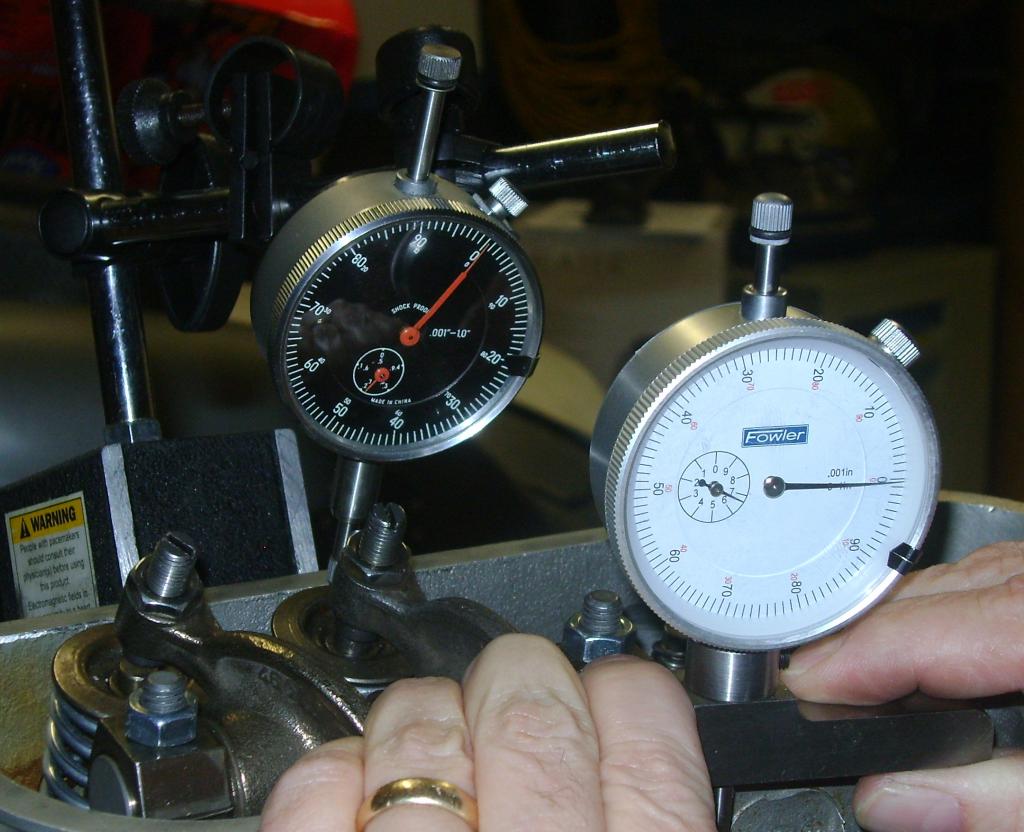
Click to view attachment I used a piece of angle and drilled it to fit the rocker shaft studs. It is mounted very securely and the dial indicator is affixed to that. I ensured that the dial indicator returns to zero (the same zero) after turning the engine and even just from jiggling the engine stand. It is quite solid.
Some math (I'm not a math teacher but I did go to engineering school - but please feel free to double check my numbers if you are hugely bored):
Advertised cam lift = .435"
5% of advertised lift (.435 *.05) = .0218" (rounded to .022 below)
Max measured lift can be .435+.022 = .457"
Min measured lift can be .435-.022 = .413"
I managed to get a measured lift of 11.55mm = .454" after just a few adjustments to the pushrod. That number is very repeatable and is just under max measured lift value from above. So it seems I got this right?
This is all on the intake valve on #1.
With that measured lift, and with one spacer under the rocker shaft mounts (not measured yet), I get the following geometry at half measured lift (again pic rotated by 914world for some inane reason):
Click to view attachmentThat geometry looks pretty good to me. I think I could get the adjuster only slightly better lined up with the valve, but I would lose some lift. A very - very small amount of lift.
Wondering if I should do this measurement and setup for all valves individually? Would love someone that has actually been down this road to chime in if possible.


 No science involved. My goal was to stay as stock as possible and when I set up the pushrods, came out with measurements within .001 to stock pushrods, so I am guessing my deck height at least as it relates to valve train was pretty close to stock.