Full Version: Jamie's 914-H6 Subaru Swap, Palm Springs California
Sounds great!
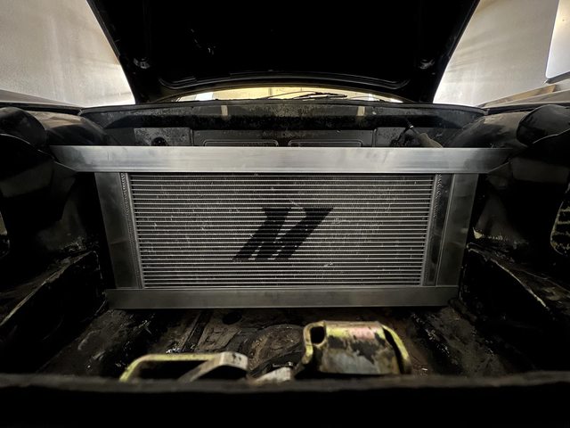
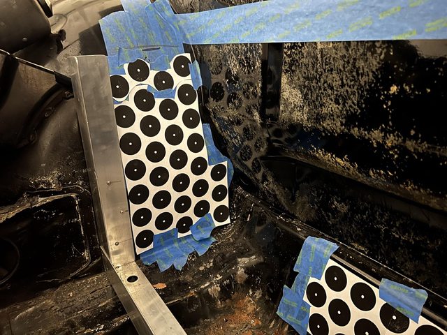
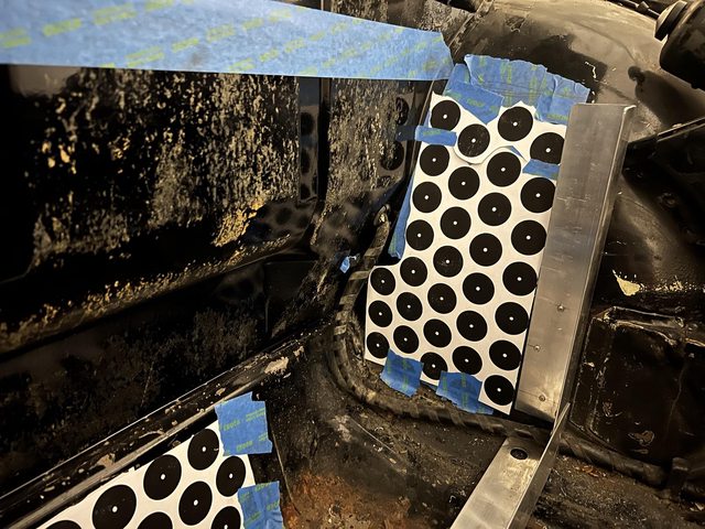
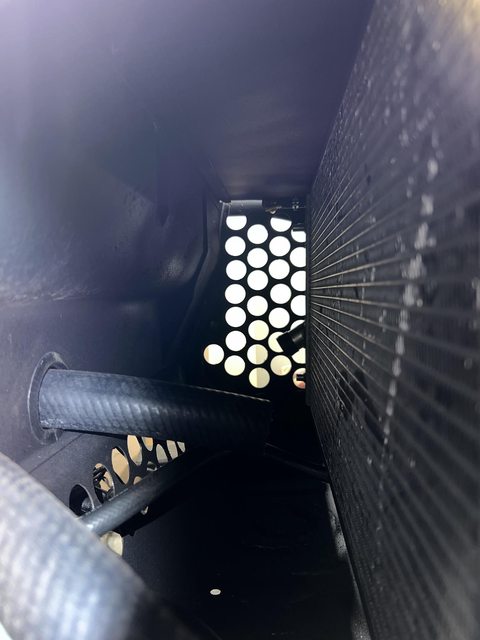
Trial-fitted the radiator. I want to try positioning it at the back of the frunk to keep the weight as inboard as possible.
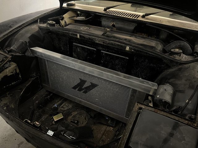
I will add a top cover behind the radiator to form a plenum to stop heated air venting to the cabin, and also aid the low pressure in the wheel wheels draw the air through from the front.
Keeping the rad towards the back also opens up the possibility of a retaining a small amount of storage in the frunk, but I'll test this setup before I commit to that.
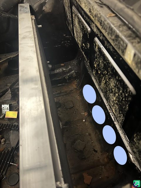
In addition to the wheel well holes, has anyone ever tried cutting holes like this at the steering rack recess to draw air? I feel like this space would create a good low-pressure area from air moving under the car.
I will add a top cover behind the radiator to form a plenum to stop heated air venting to the cabin, and also aid the low pressure in the wheel wheels draw the air through from the front.
Keeping the rad towards the back also opens up the possibility of a retaining a small amount of storage in the frunk, but I'll test this setup before I commit to that.
In addition to the wheel well holes, has anyone ever tried cutting holes like this at the steering rack recess to draw air? I feel like this space would create a good low-pressure area from air moving under the car.
QUOTE(jamlip @ Mar 6 2024, 11:10 PM) 
Trial-fitted the radiator. I want to try positioning it at the back of the frunk to keep the weight as inboard as possible.
I will add a top cover behind the radiator to form a plenum to stop heated air venting to the cabin, and also aid the low pressure in the wheel wheels draw the air through from the front.
Keeping the rad towards the back also opens up the possibility of a retaining a small amount of storage in the frunk, but I'll test this setup before I commit to that.
In addition to the wheel well holes, has anyone ever tried cutting holes like this at the steering rack recess to draw air? I feel like this space would create a good low-pressure area from air moving under the car.
How fast do plan on driving Jamie. These cars get pretty light around 125mph. Any added air beneath will have its effect.

In addition to the wheel well holes, has anyone ever tried cutting holes like this at the steering rack recess to draw air? I feel like this space would create a good low-pressure area from air moving under the car.
Yes.. This is mine..
Click to view attachment
Yes.. This is mine..
Click to view attachment
Interesting, thank you. Do you have the fenders cut out as well?
In addition to the wheel well holes, has anyone ever tried cutting holes like this at the steering rack recess to draw air? I feel like this space would create a good low-pressure area from air moving under the car.
Yes.. This is mine..
Click to view attachment
QUOTE(slowrodent @ Mar 7 2024, 07:14 AM)
In addition to the wheel well holes, has anyone ever tried cutting holes like this at the steering rack recess to draw air? I feel like this space would create a good low-pressure area from air moving under the car.
Yes.. This is mine..
Click to view attachment
No.. I just have these as exit holes, and I have opened/connected the front holes as inlets. My radiator sits to the rear of the frunk. It;s a bit unorthodox I suppose. We'll see how it flows once its moving  My goal was to be able to fit a spare tire in the frunk.
Kevin
My goal was to be able to fit a spare tire in the frunk.Kevin
Right-o. Any thoughts on this arrangement before I drill a bazillion holes in the car?
Under-cooled, over-cooled, structurally unsound, etc...
Under-cooled, over-cooled, structurally unsound, etc...
QUOTE(slowrodent @ Mar 7 2024, 09:10 PM)
No.. I just have these as exit holes, and I have opened/connected the front holes as inlets. My radiator sits to the rear of the frunk. It;s a bit unorthodox I suppose. We'll see how it flows once its moving
My goal was to be able to fit a spare tire in the frunk.Kevin
@slowrodent , Can you share details of how/where the spare tire fits? Is it a regular size spare or one of those collapsible deals?
QUOTE(jamlip @ Mar 9 2024, 12:11 AM)
Right-o. Any thoughts on this arrangement before I drill a bazillion holes in the car?
Under-cooled, over-cooled, structurally unsound, etc...
Nah. Just do it. We learn from both achievements and mistakes. Besides, you'll fix anything that doesn't work out, right?
QUOTE(jamlip @ Mar 9 2024, 03:11 AM)
Right-o. Any thoughts on this arrangement before I drill a bazillion holes in the car?
Under-cooled, over-cooled, structurally unsound, etc...
@jamlip , that looks interesting. I like the new approach to radiator mounting. If nothing else, all those holes should create a nice soft crush zone during front collision!
 I’ll be watching to see where you go with this.
Just FYI gents, as Im not trying to hijack... This is mine. And I may not have adequate "holes", but I can add more as I learn more. My theory is mount skinny full-diameter spare on the frame I built, and then allow air to flow through the front under the spare tire.. (Ignore blue coolant hose presently blocking flow ) I have test fit the tire and it works quite well. I will add air-directing ductwork as required.
Click to view attachment Click to view attachment
) I have test fit the tire and it works quite well. I will add air-directing ductwork as required.Click to view attachment Click to view attachment
That's a fantastic color on the 912. What is it?
QUOTE(krazykonrad @ Mar 9 2024, 04:31 PM)
That's a fantastic color on the 912. What is it?
Thx. Bahama Yellow.
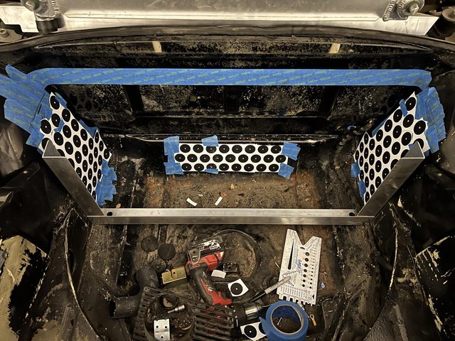
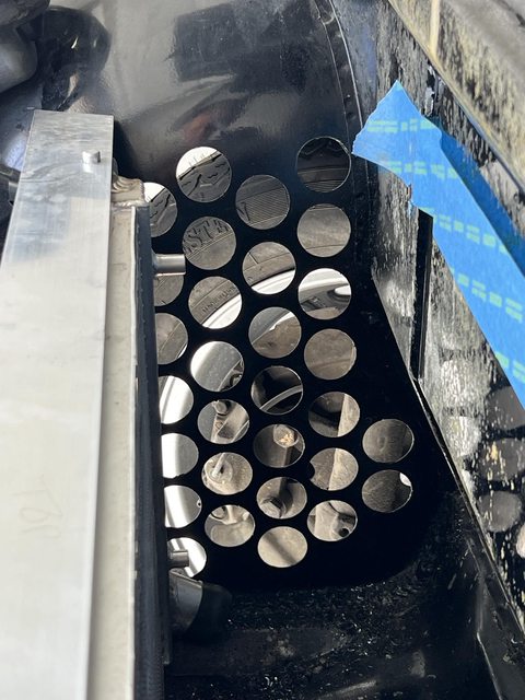
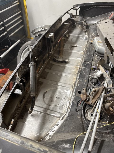
OK, went ahead with the holes as templated…
Dang you been busy Jamie! Let me know if you need anything.
Randy
Randy
The frunk radiator box now has a top cover, and I routed pipes from the engine through to the front.
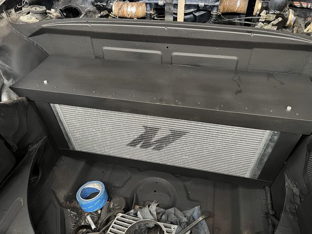
Against my better judgement I decided to put the heater pipes inside the cabin, on top of the tunnel - my reasoning being that I do occasionally like a good thrash on some of the dirt roads out here in the desert.
(Still waiting on Amazon for the connectors to get the hoses to the radiator inlet / outlet)
I've wrapped the pipes with fiberglass pipe wrap to help contain heat and am in the process of building a secondary tunnel structure around them to raise the shifter to around the same height as it would be in the MR2 which it came from. I'll then sheath it with FRP and cover it in charcoal Perlon so it looks somewhat factory.
I'm wondering if I could somehow use the tunnel to stiffen the chassis a touch at the same time, although I'm simultaneously not that keen to add more weight than necessary to this thing.
QUOTE(jamlip @ Mar 27 2024, 09:28 AM)
I'm wondering if I could somehow use the tunnel to stiffen the chassis a touch at the same time, although I'm simultaneously not that keen to add more weight than necessary to this thing.
Hi James I do not think it will help twist but you could build a truss from small square tubing to serve as a frame for your extention. Wouldn’t weigh much but would be strong. Welded or bolted to the existing tunnel would give you some extra anti flex protection.
I have this square tube framework I made but decided not to use. It already has the mount points for the MR2 shifter. I’d be willing to let it go to a good cause.
Click to view attachment
Click to view attachment
Really appreciate it but we're on opposite coasts and it's so easy just to make one.
I have this square tube framework I made but decided not to use. It already has the mount points for the MR2 shifter. I’d be willing to let it go to a good cause.
Click to view attachment
QUOTE(East coaster @ Mar 27 2024, 06:21 PM)
I have this square tube framework I made but decided not to use. It already has the mount points for the MR2 shifter. I’d be willing to let it go to a good cause.
Click to view attachment
QUOTE(jamlip @ Mar 29 2024, 01:40 PM)
Really appreciate it but we're on opposite coasts and it's so easy just to make one.
QUOTE(East coaster @ Mar 27 2024, 06:21 PM)
I have this square tube framework I made but decided not to use. It already has the mount points for the MR2 shifter. I’d be willing to let it go to a good cause.
Understood, just thought I’d offer since it will collect dust in my shop and ultimately be cut up for some other use of the tubing. Good luck with your project!
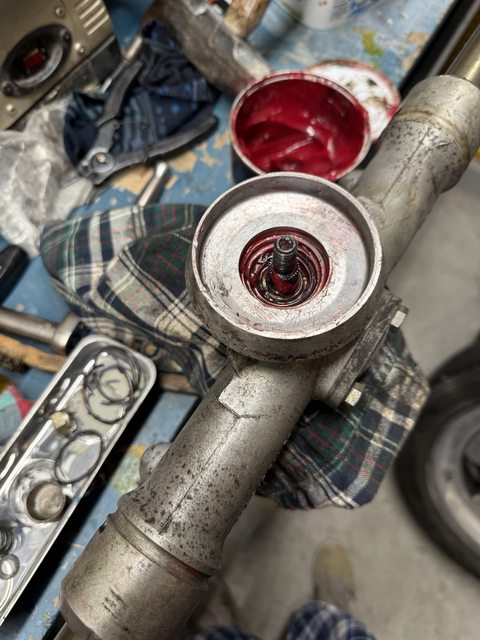
Pulled-apart steering rack and am waiting on bearings and seals so I can rebuild.
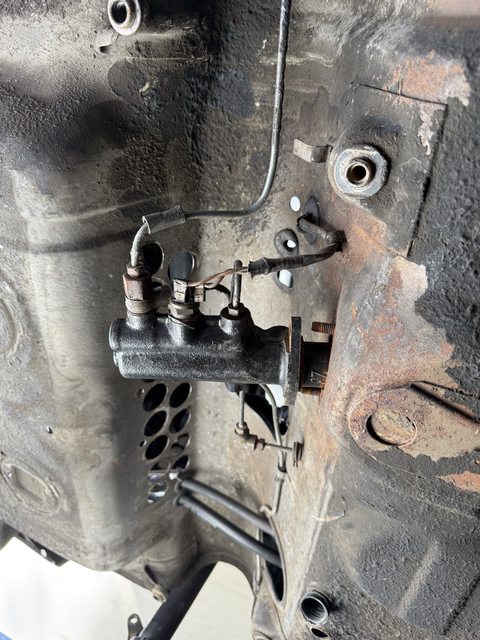
Discovered that the car had a 23mm master cylinder (think the front brakes were Volvo), so I pulled that. I have a spare 19mm master cylinder in my Box of Stuff, which I will use. Front brakes will be 3.2 calipers, which I've ordered and am waiting on.

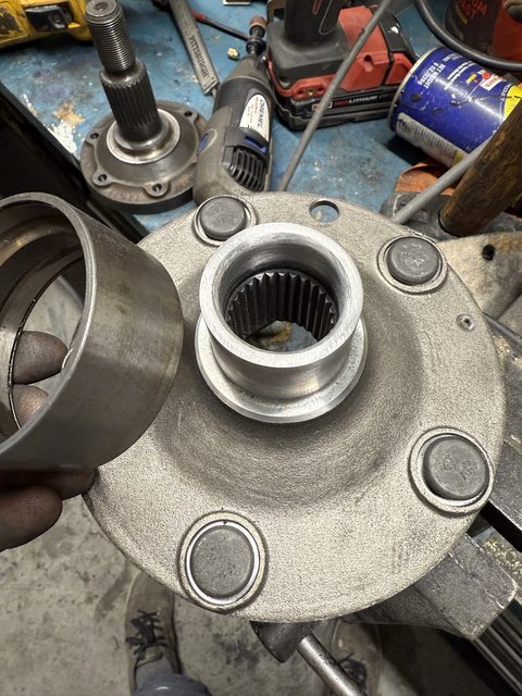
Cut down my rear hubs. I didn't want to use a 5mm spacer on the outside. Used the stub axel as a reference to grind the cut square, and old bearing race to make sure I had cut off enough to grip the bearing properly. I went about 0.8mm undersize.
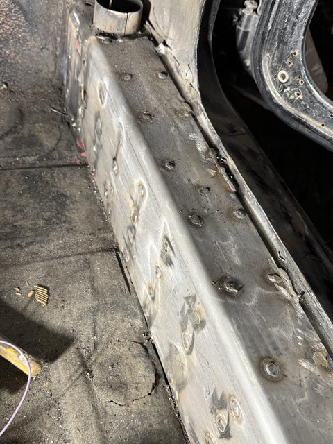
Welded in a new tray. After this I need to drop the engine and do the hellhole. Can't wait.
Made a little bracket for the hydraulic master cylinder. Came out nice - will get a photo.
Discovered that the car had a 23mm master cylinder (think the front brakes were Volvo), so I pulled that. I have a spare 19mm master cylinder in my Box of Stuff, which I will use. Front brakes will be 3.2 calipers, which I've ordered and am waiting on.
Cut down my rear hubs. I didn't want to use a 5mm spacer on the outside. Used the stub axel as a reference to grind the cut square, and old bearing race to make sure I had cut off enough to grip the bearing properly. I went about 0.8mm undersize.
Welded in a new tray. After this I need to drop the engine and do the hellhole. Can't wait.
Made a little bracket for the hydraulic master cylinder. Came out nice - will get a photo.
Latest updates. Progress is molasses-slow.
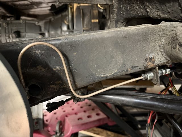
Made up some new cunifer brake lines.
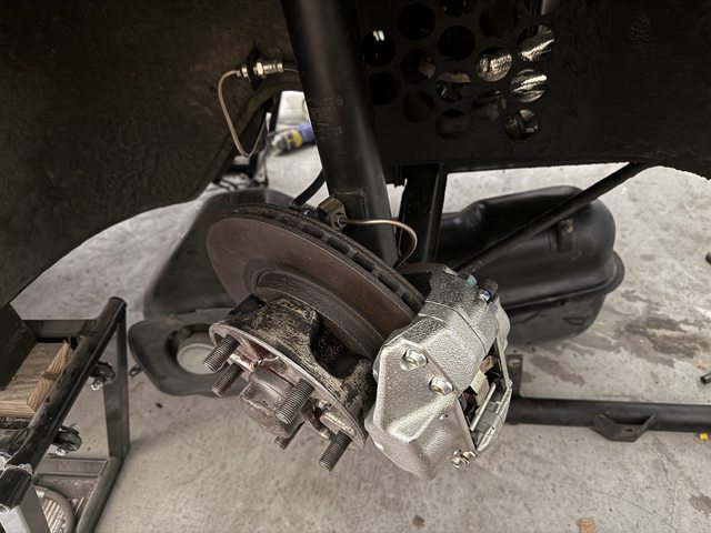
Cleaned the front hubs and fitted new bearings.
Fitted new front brakes. They're SC / 3.2 Carrera units, but I wonder now if I should have gone with Boxster calipers.
Started on the stiffening kit (then ran out of gas halfway through).
Here's the bracket I made for the clutch slave cylinder...
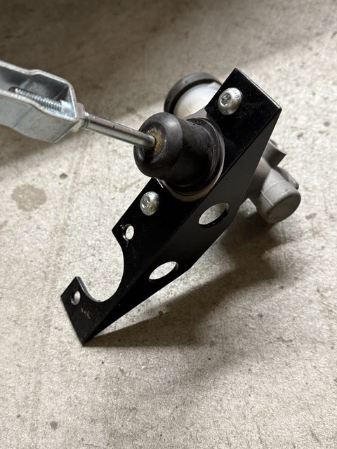
... the hardware needed some adaptation to make it fit...
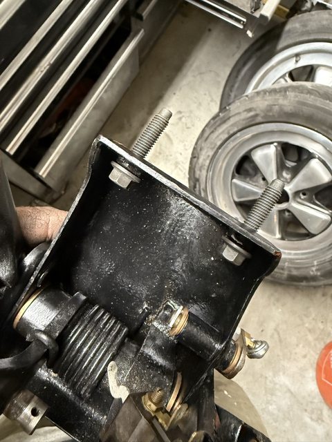
.... and the through-bolts on the pedal cluster needed lengthening. Because I was out of welding gas, I cut off the old bolts and drilled and tapped them to hold these new bolts in place.
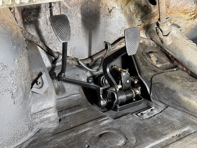
Here's the pedal cluster in place. I cleaned it up, painted it and fitted new bronze bushings. I've done four of these in my life, and I'm a lot more efficient now than my first attempt.
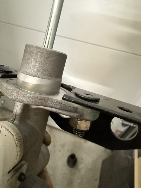
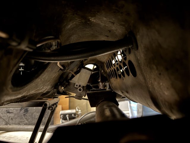
Clutch master cylinder bracket in place on the underside.
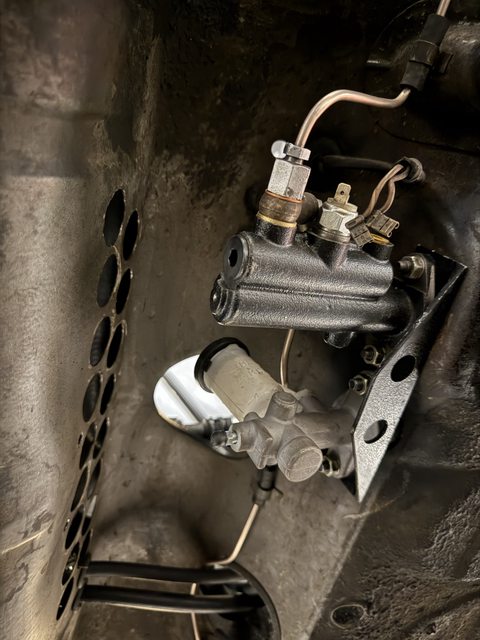
Realizing that I won't be able to fit the steering rack because that reservoir is in the way
Made up some new cunifer brake lines.
Cleaned the front hubs and fitted new bearings.
Fitted new front brakes. They're SC / 3.2 Carrera units, but I wonder now if I should have gone with Boxster calipers.
Started on the stiffening kit (then ran out of gas halfway through).
Here's the bracket I made for the clutch slave cylinder...
... the hardware needed some adaptation to make it fit...
.... and the through-bolts on the pedal cluster needed lengthening. Because I was out of welding gas, I cut off the old bolts and drilled and tapped them to hold these new bolts in place.
Here's the pedal cluster in place. I cleaned it up, painted it and fitted new bronze bushings. I've done four of these in my life, and I'm a lot more efficient now than my first attempt.
Clutch master cylinder bracket in place on the underside.
Realizing that I won't be able to fit the steering rack because that reservoir is in the way
QUOTE(jamlip @ Jan 28 2025, 03:31 PM)
Realizing that I won't be able to fit the steering rack because that reservoir is in the way
I used a Wilwood clutch master cylinder and a remote reservoir. The reservoir is from a RHD 924 S. I mounted it right behind the brake master cylinder.
Thanks Clay, I’ll look into it
Can anyone help me find a starter that will fit?
The solenoid on the current one is in a position that means it hits the underside of the trunk floor. I can't raise the engine into place.
I'm looking for something with the solenoid clocked like this…
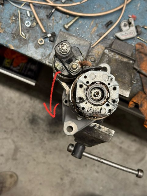
A while back Kent mentioned there was one that works, but he couldn’t remember which car it was for.
The solenoid on the current one is in a position that means it hits the underside of the trunk floor. I can't raise the engine into place.
I'm looking for something with the solenoid clocked like this…
A while back Kent mentioned there was one that works, but he couldn’t remember which car it was for.
QUOTE(East coaster @ Jan 29 2025, 04:31 AM)
Thank you! Subaru 17717, apparently. eBay came through with a remanufactured unit at $40
Jamie, check Rock Auto. I bought the Denso reman which was available in 1kw or 1.2kw. Still works great after 11 yrs. That 1.2kw really spins the 6 quickly.
Thanks! I did - it was $20 more for a different (or perhaps even the same?) no-name reman (plus a mail-in core charge of $30), so I decided to roll the dice.
A Denso reman was $110. That’s fine, but Denso use 3P suppliers for their remanufactured parts, so it could be the same thing anyway.
I wouldn’t exercise this logic on set of crank bearings or a clutch, but this is part is easy to swap out if there’s a problem later.
A Denso reman was $110. That’s fine, but Denso use 3P suppliers for their remanufactured parts, so it could be the same thing anyway.
I wouldn’t exercise this logic on set of crank bearings or a clutch, but this is part is easy to swap out if there’s a problem later.
This is a "lo-fi" version of our main content. To view the full version with more information, formatting and images, please click here.