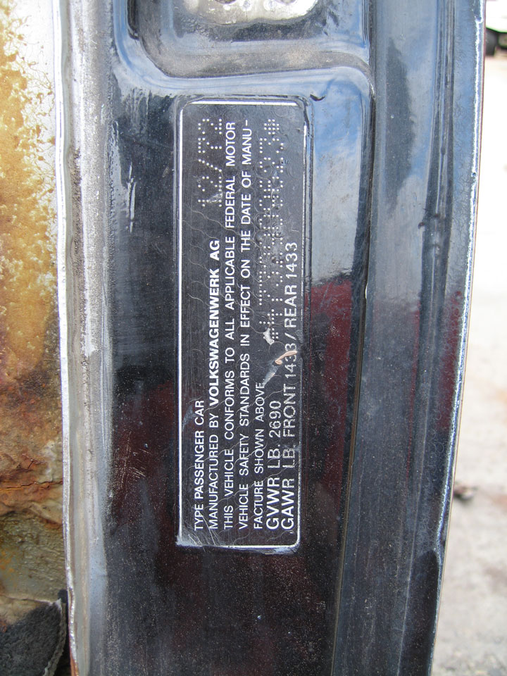
I've been working on the rotisserie for about 3-4 weeks now. I went to Guelph, Ontario for about a week with Kirsten to see the family's old farmhouse which is amazing.
I haven't gotten to assembling the hoist cages yet - I'm concentrating on what I am calling the "yokes" - the parts that attach to the car (like the yoke of an engine stand only bigger). The drawing posted above is pretty small, but here are close ups to show the pivots that have taken a lot of my time the past few weeks. I call the individual pieces of the pivots, "leaves" as they are interleaved for strength, 1/4" plate x 4", they are.
Click to view attachmentClick to view attachmentIt would likely have been easier to grind the shapes from rectangles cut from a strip, but I made them from 4" squares and circles that I cut in half on the band saw and welded to each other. The ones on the far right are for the pivot at the car to yoke; there are 8 for now but I need to do still eight more.
The bigger ones to the left are for the spanning beams to the pivot plate. -I've got names for all the parts, I suppose.

I changed the design to make the outers longer halfway through making them so those pieces have 2 beads on them. There are 4 outers - 2 for the 2 yokes, and a total of 20. So 4 and 20 black birds baked in a pie.

You can see one of my 12" filter fans with re-useable aluminum mesh filter - I have 3 going as it is hot here, even still.
Click to view attachmentSome of my favorite clamps. The aluminum is way too thin a backer for what I am about to do here, and ends up seriously warped.
Click to view attachment2-3 passes each, cooling between, they still warp a little with the heat. I maybe should have preheated them. I beat them flat with a hammer though. The circles ended up being a marginal bit thicker than the squares. It would be nice to have a mill, but I have a grinder. Derek, you should remember that verysame bell grinder wheel that we used on the lathe table. It has slowly got shorter.
The big plates are to be mounts for the casters. An odd size, I had to make them from cut 8" squares of 1/4 inch plate.
The smaller pieces with the 3/4" holes marked on the left are to be backing plates for where the car is attached, 3/16 plate. I made 4 But realize I have to use just washers in back as the trunk floor divides the top and bottom bumper mount holes. This would prove to be just the first complication presented by the cars rear end.
DOM tube for the main pivots, ready to be faced at right.
Click to view attachment 
That is some gnarly stuff there, the edges on the circles I mean, My grinder will fix them.
Click to view attachmentDrilled the holes first this time. These will be the mounts to the car. The saw gets its own fan.
Click to view attachmentThe drawing doesn't have them, but I added spacers to the design of the pivots, so the leaves don't bend under side load. The assembly just behind the flap wheel is 2 leaves joined by the spacer. To the left of that is similar with a base, and the process there in the vice.
Click to view attachment3/4" shoulder bolts.

4" long for the beam pivots and a 2.5" at each end. Got these from McMaster car, all grade eight or equivalent, I got everything in socket head cap screw, black oxide finish for the hardware.
Click to view attachmentThe "forearms" of the yoke are longer than in the drawing to allow greater access.
Click to view attachmentThe other setback at the rear, the mounts point out by10 degrees of straight. I got this all jigged up and even tacked together before realizing the error in my thinking here. That is a box of 3 of the 15" version of the filter fans there. They do like twice the cfm's as the 12", so 750 and 1500 cfms for the 12 and 15 inch respectively, 3 of each, plus the crazy contraption seen on the bench above, I hope will be adequate for the paint booth.
Click to view attachmentABout the rear bumper, the plan is to do both to fit to the front which is straight on, and to make adaptor plates to fit the back, which is also closer together by a bit iirc. The outer pivots will have another set of leaves at the outers at all 4 corners - those other 8 leaves I've yet to make. I plan to triangulate, a 4" x 1/4" triangle plate at the inner of the elbows also, a web elbow for strength. I've got both ends welded, a bit more than in this pic now, and soon to mount the leaves right to the middles there.
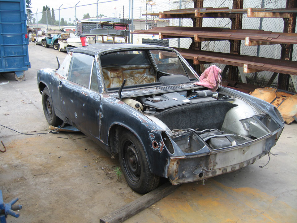
Click to view attachmentMy little bandsaw has been busy. I was able to straighten out the tabs to get it to cut straight again. For a bit I was having to grind them straight, ever piece. I had to weld the vertical there and 1 of the horizontals, too as it is all remnants. With the car on the dolly, the adriatic jack stands have procreated. ... proud papa there in back.
 Click to view attachment
It is coming along, working on it this weekend, I will start attaching the span pivot leaves with spacers which I'll need to cut and then attach those to yokes directly.
I'm hoping that once the yokes, with the labor-intensive pivots are done, that the rest of the thing will go far more quickly

.


![popcorn[1].gif](http://www.914world.com/bbs2/style_emoticons/default/popcorn[1].gif)


 Sorry to get back so late
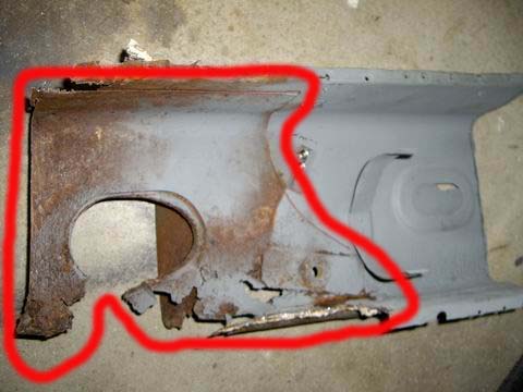
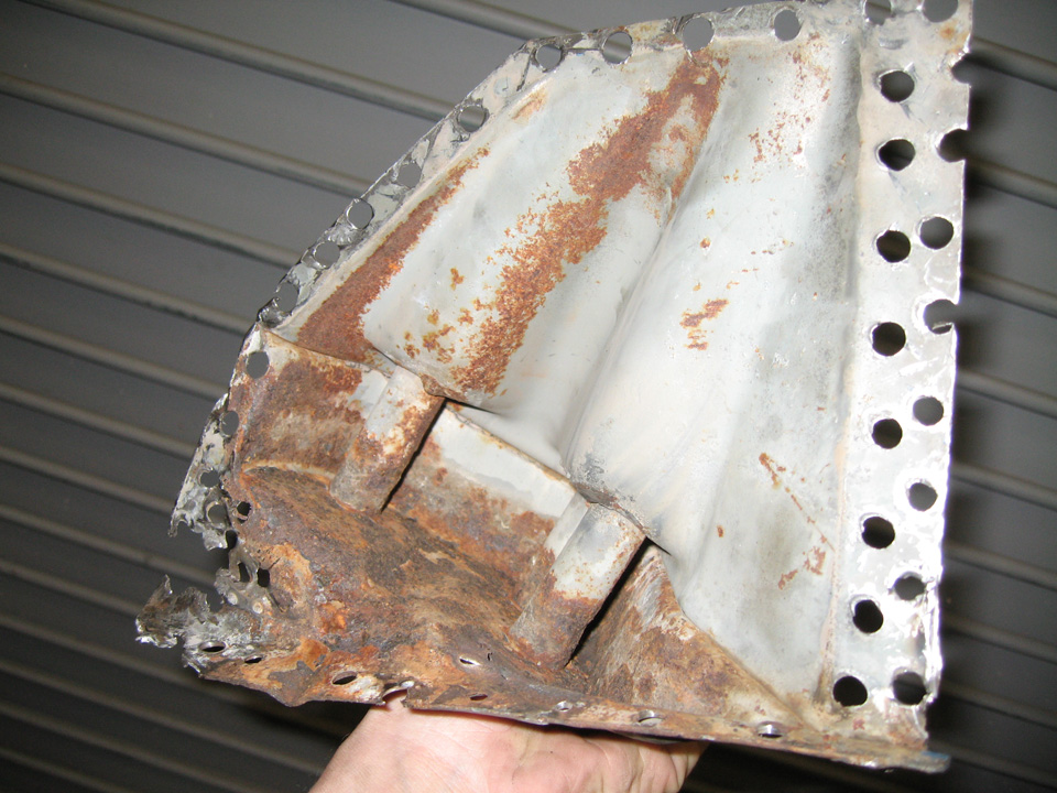
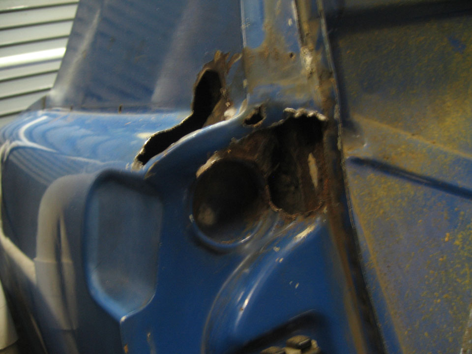
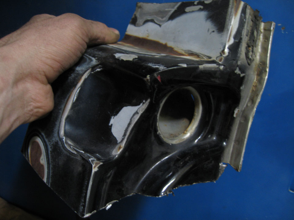
 It bothered me for a bit, but I hope it will be ok. It is a learning experience for me here.
  Not pleased with the results of a screw driver test there.
 I've got the metal to fix it, thought I might have had to before, so maybe I can make short work of this. I won't post more pics of it until the sight of what I have done does not induce vomiting.

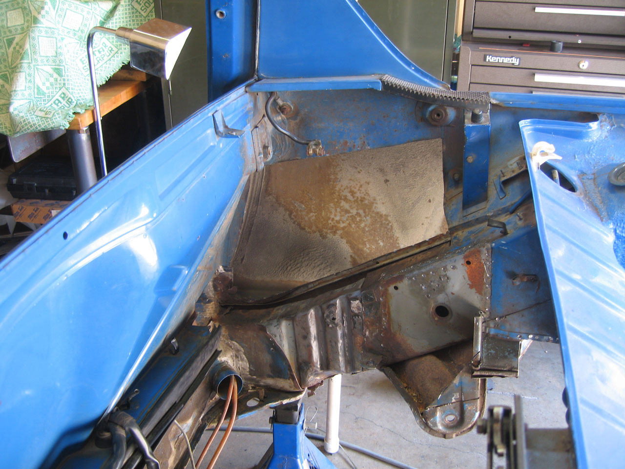
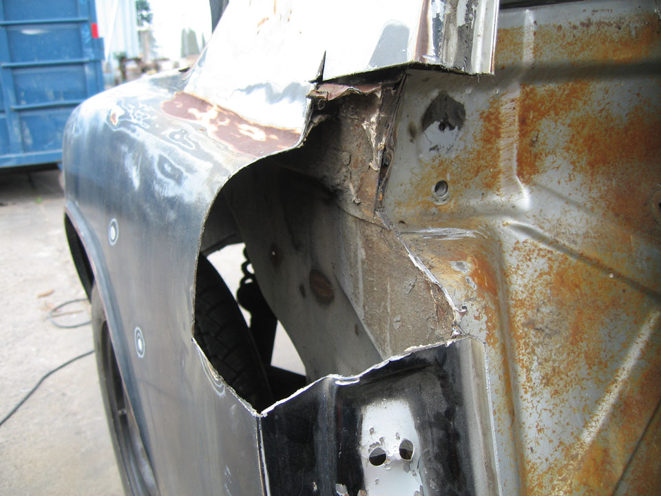
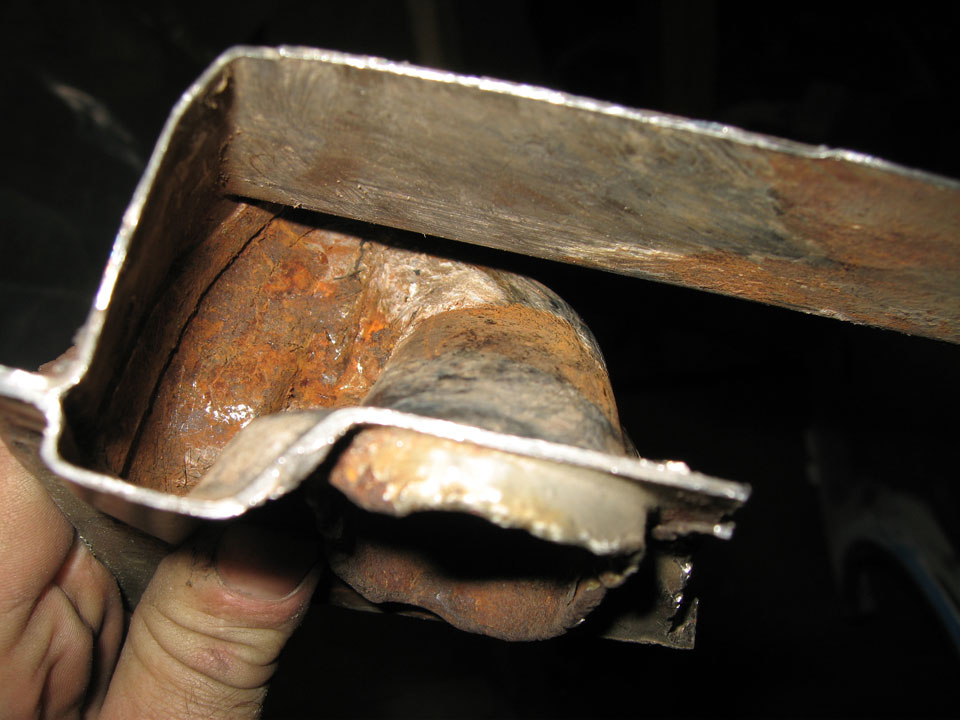
 . I'll get to some of the work I did on that in a post later. For now I'll catch up with the jack point repair.
  so..
so..

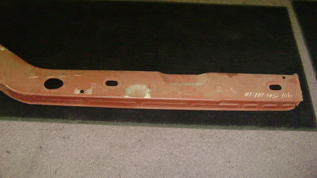
 Very productive, I know, but they are somehow different, like in there temper or something because they weigh about the same, but they are just different..
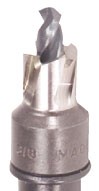
  I started out just using a regular drill bit, but it does make extra work. There are few options for spot weld drills, even just at Eastwood, but I went with the expensive ones. I got replacement guide bits and cutting tips, but I'm still using the same one after a ridiculous amount of welds drilled. I use cutting oil fanatically. The drawback to spot weld drills is they are all huge, the hole they make.
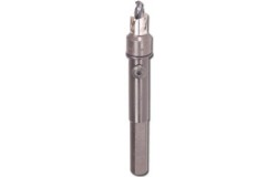


![yellowsleep[1].gif](http://www.914world.com/bbs2/style_emoticons/default/yellowsleep[1].gif)
 :clampsandbolts: