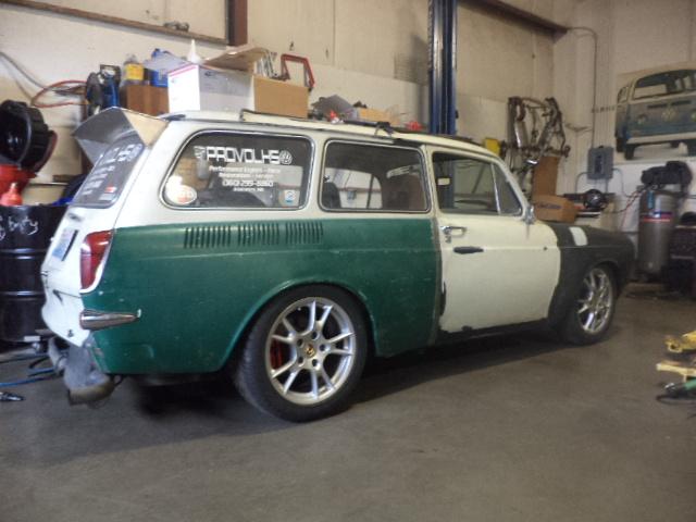
So I'm basically finished with most of the widening process and I thought I would come clean with it and confess my sins. . .
I began going a different route entirely and I plan to make a set like originally planned, but I have planned for later this year. So in the K.I.S.S. vein, I merely kept is simple stupid.
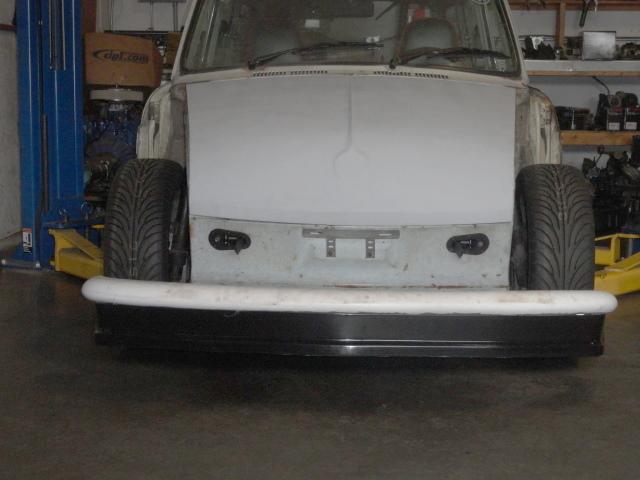
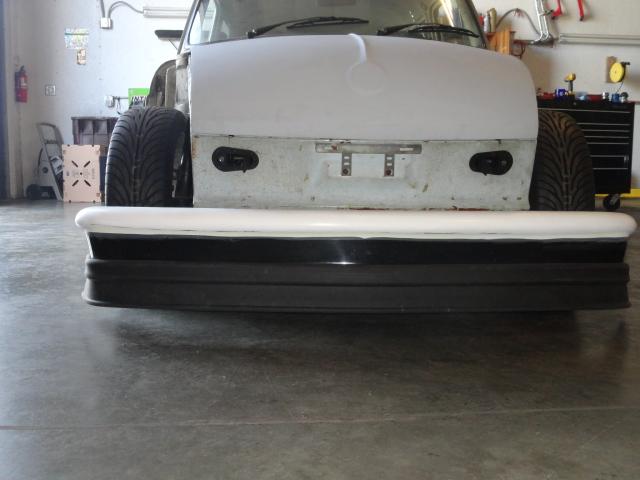
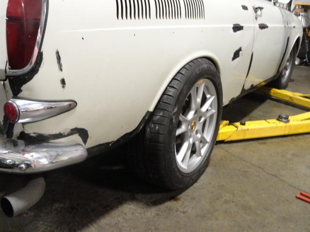
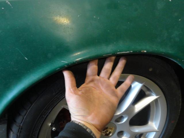
For the front, that was easy. I removed my wheel spacers and the longer studs and threw on the shorter studs and mounted the wheels directly to the hubs. Then with a few vigorous pulls, I was able to massage the lips out about 1/2" from stock and there are currently no rubbing issues. Now, I will need to re-set the rear door gap, but that should be pretty easy.
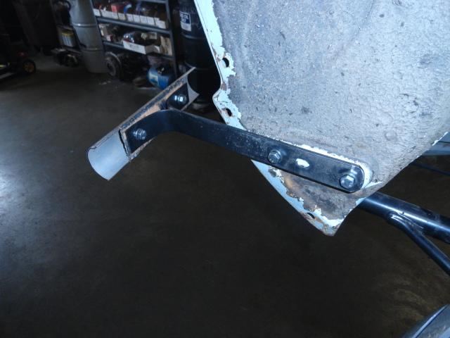
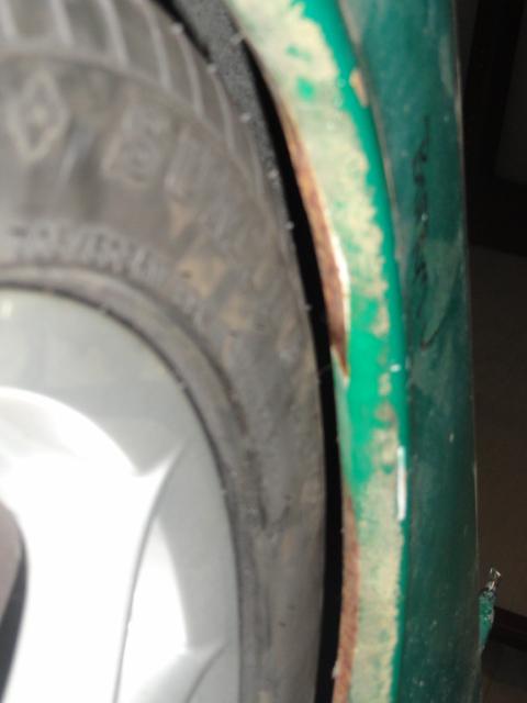
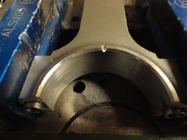
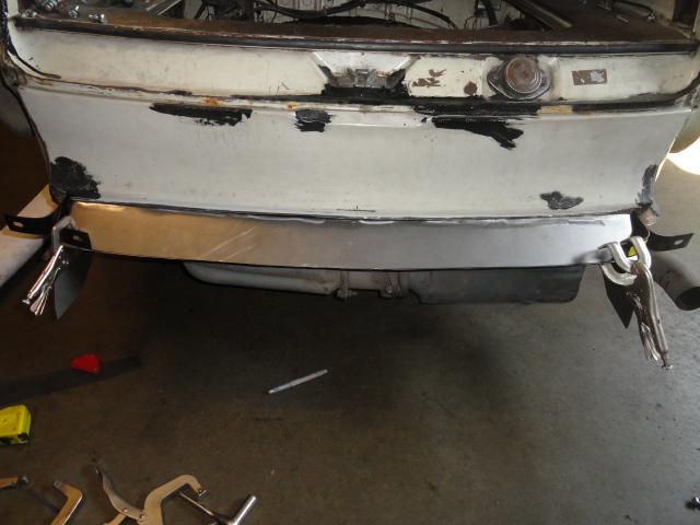
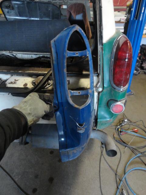
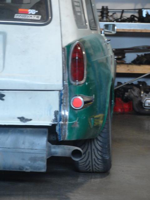
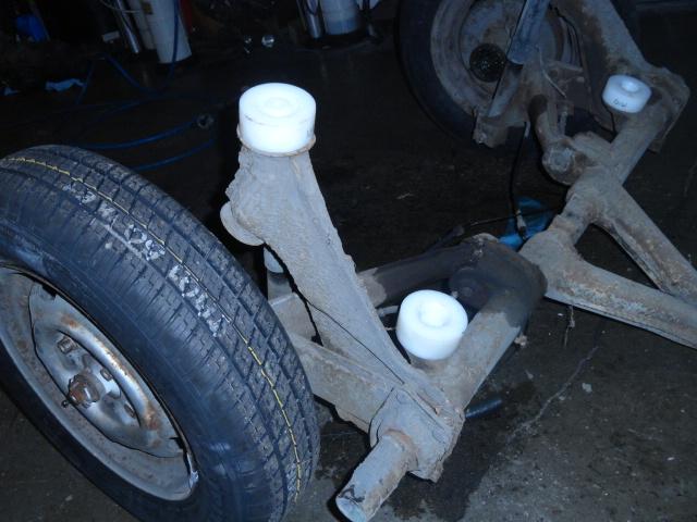
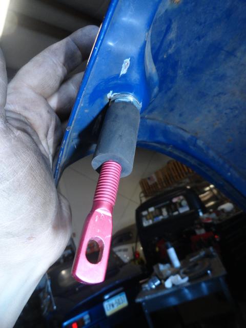
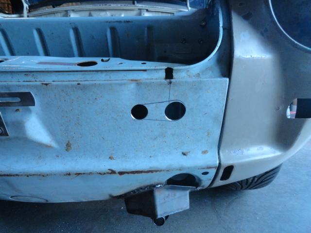
The rears were another story. I had to overcome this. . .
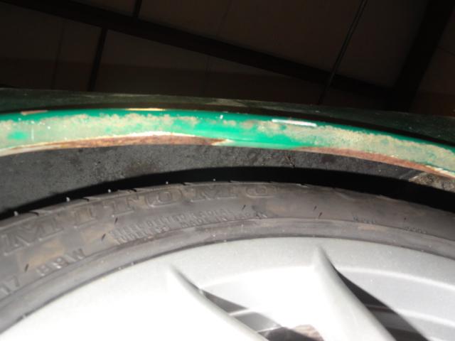
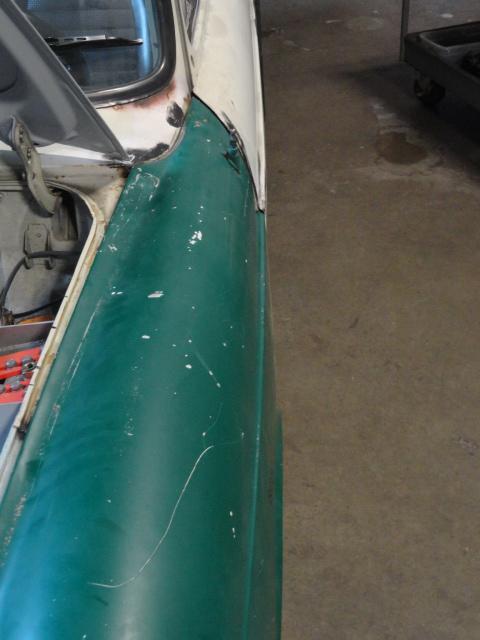
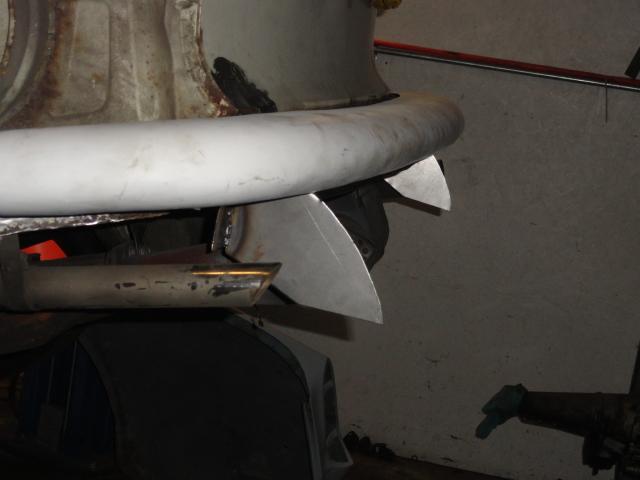
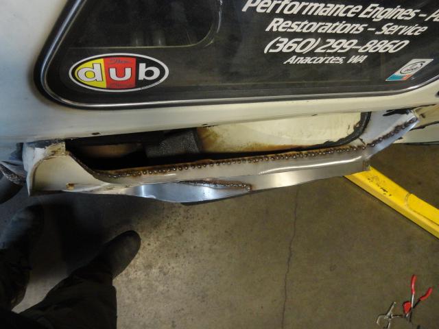
I decided that I wanted to be more subtle with this set, so I bumped out the fender arches 3". This also forced me to have to extend the engine cooling air duct lip as well. The front bottom edge had to come out 3" or so to ensure and angled to the factory rocker width. The rear bottom edge had to be extended so that the rear edge of the wheel arch would cover the tire.
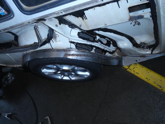
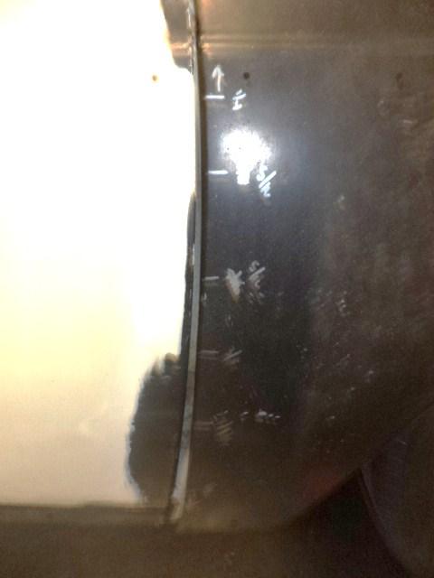
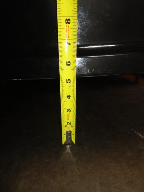
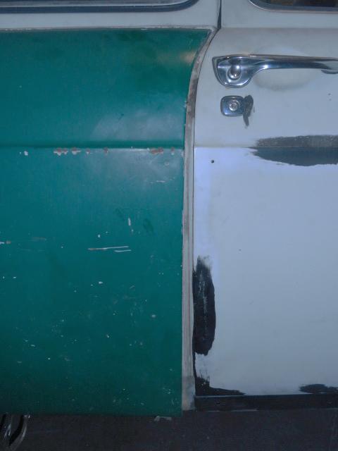
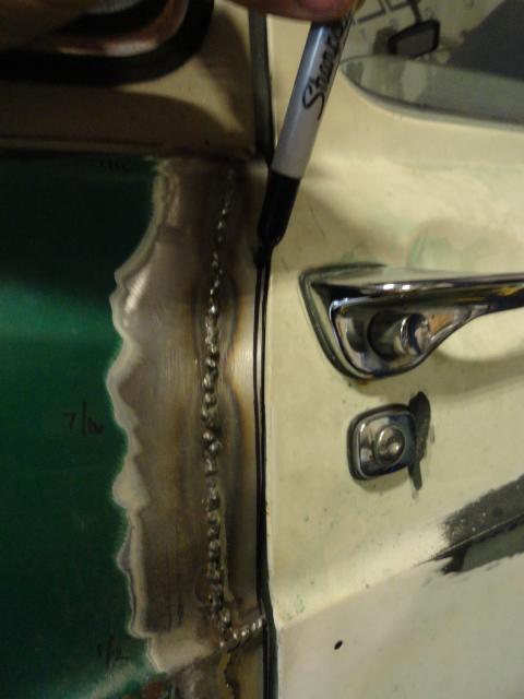
Once this was done, the rear door gap was HUGE. It went from a sloppy 7/16" at the top to a portly 1.25" at the bottom.
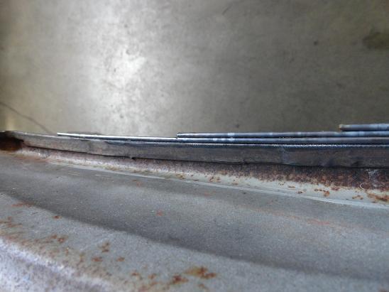
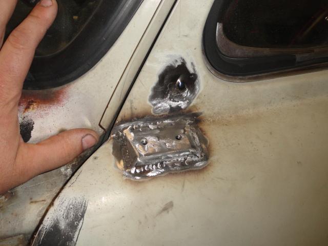
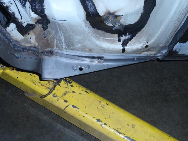
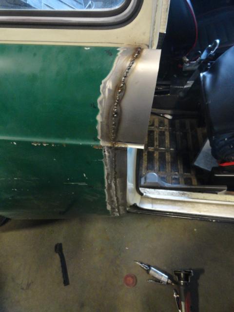
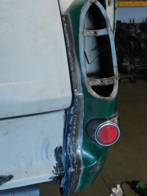
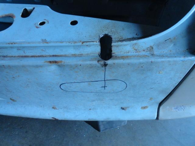
To correct this was pretty simple. Once the fender was installed, I marked a line 3/8" from the fwd edge with a Sharpie and used a cut-off wheel to cut the front edge off the fender.
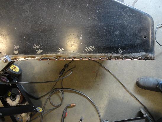
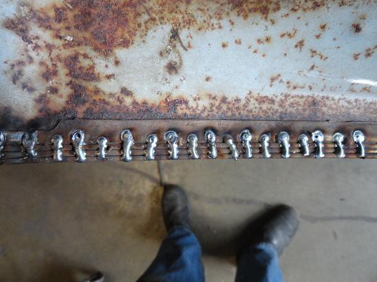
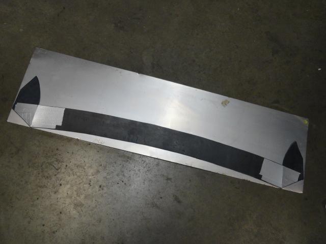
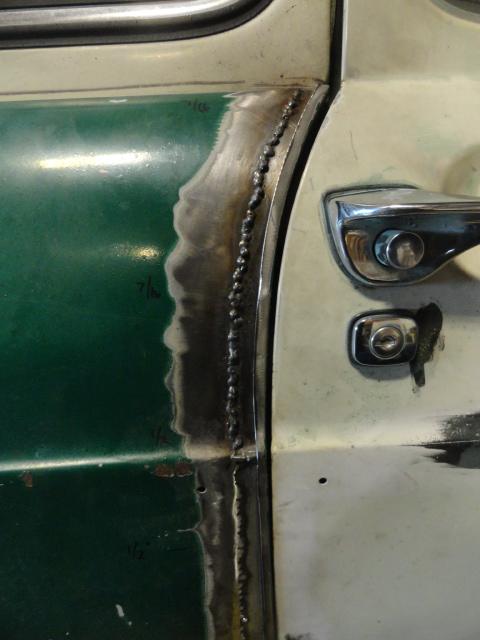
Then I bent some metal in the shape of the top section so that t fit tightly and welded it in. Then I made a strip for the bottom section and welded it in.
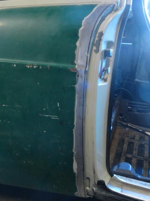
After that I cut the sections down enough that I was almost able to shut the door and used a Sharpie to mark a cut line. Then I placed the front strip on the filler, set the gap to 3/16" and tacked it in place.
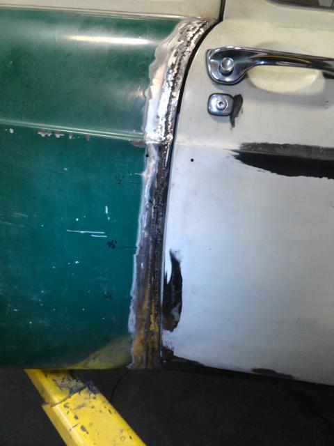
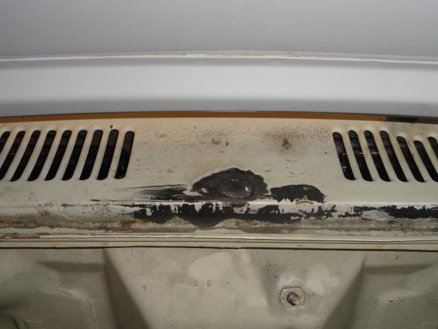
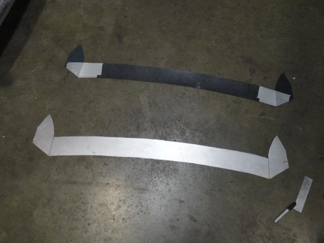
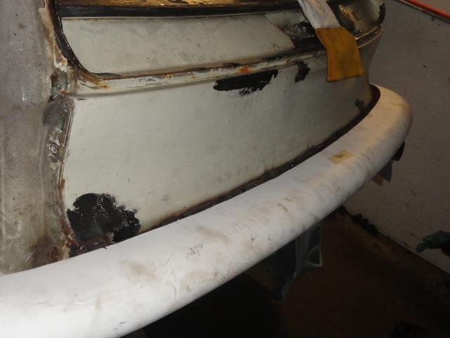
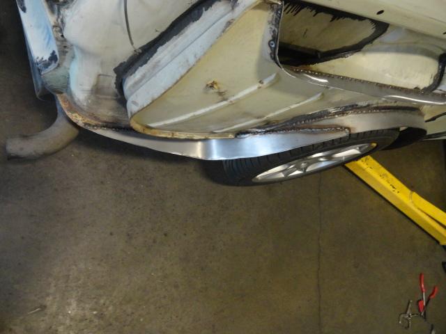
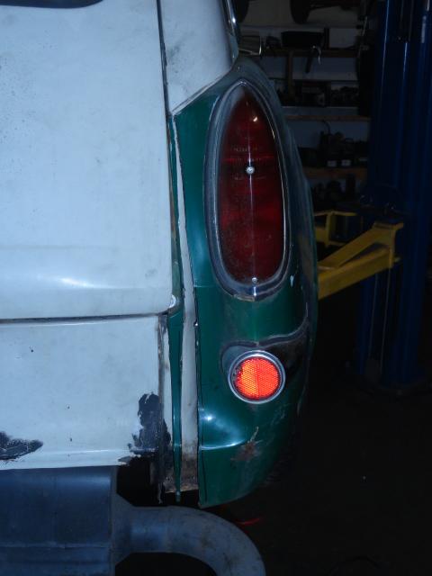
The rear seam had issues as well. The gap was too small at the top, normal in the middle and about 3/4" at the bottom.
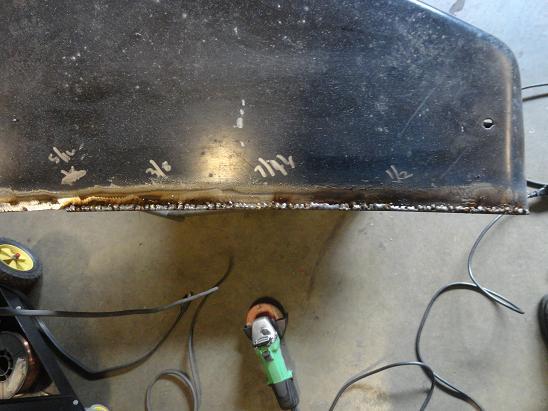
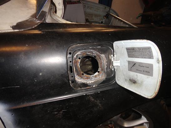
The rear was easy. I cut a section out of a donor fender that was about 1/2" at the top and about 1" at the bottom. Then I marked a cut line on the fender and cut just the edge off. Then I mounted the donor strip to the car and pushed the fender over the donor. Once it was in place, I tacked it in place.
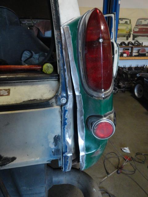
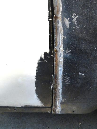
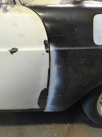
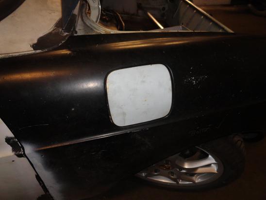
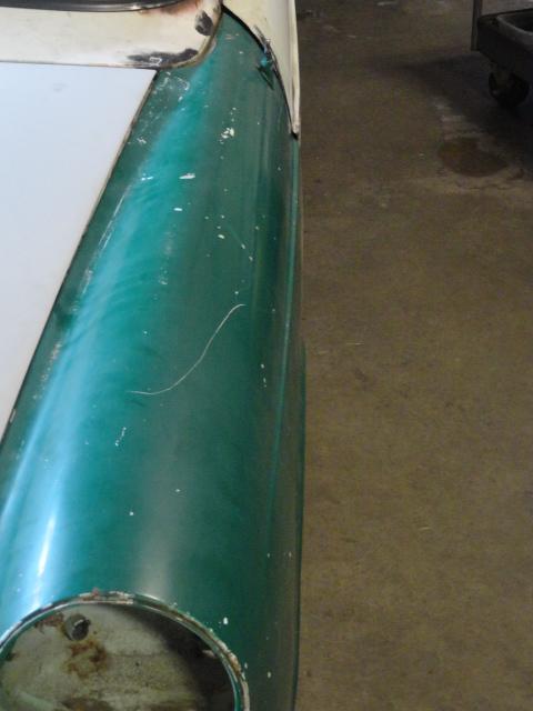
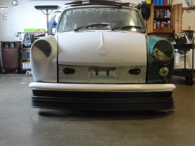
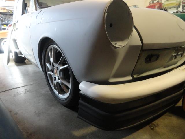
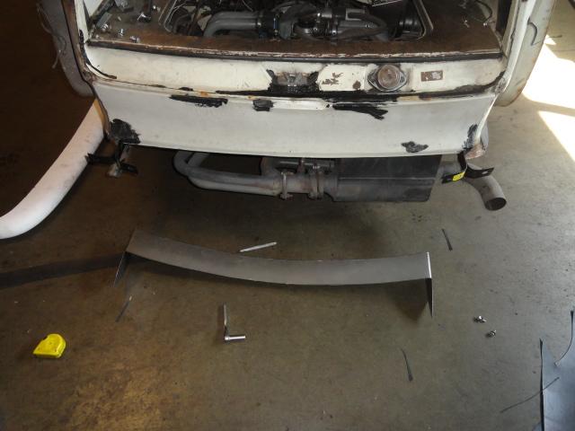
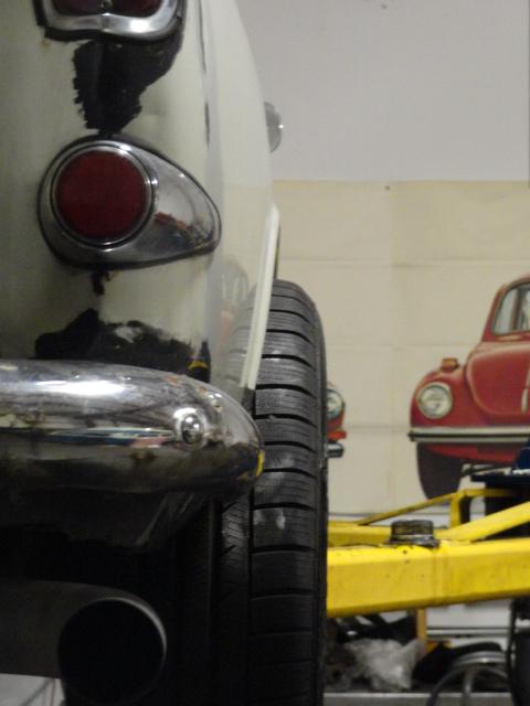
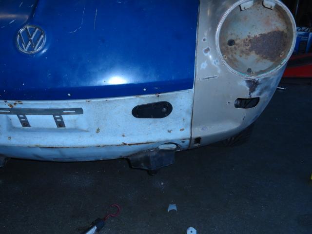
Here's the results. . .
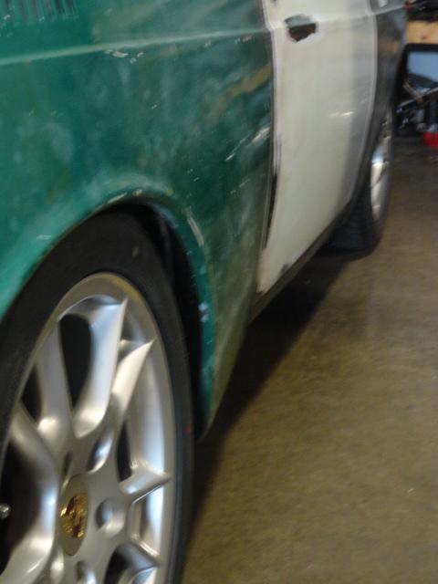
Now that I have the passenger side done and can use it as a pattern, the drivers side will be much quicker. Unfortunately, the drivers side has a bit of rust repair as well.
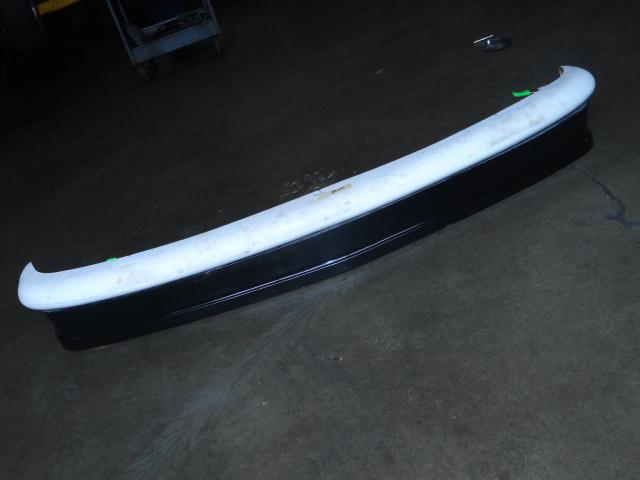
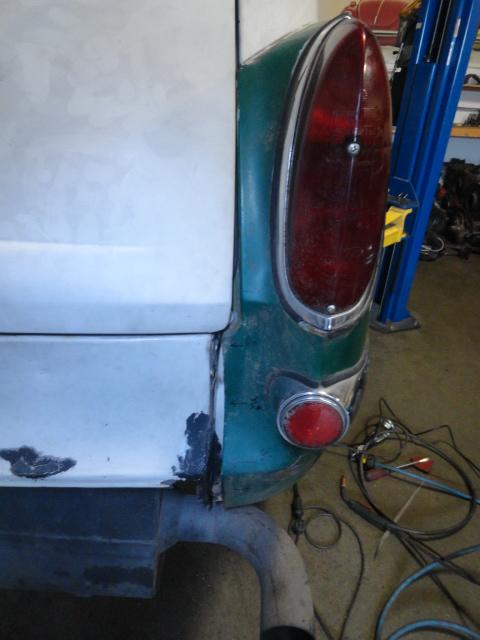
This rear fender is not totally done though as I have some rear ducting to fabricate but the fender is basically a done.
 shouldn't be an issue with 255/40/17 tires stuffed in.

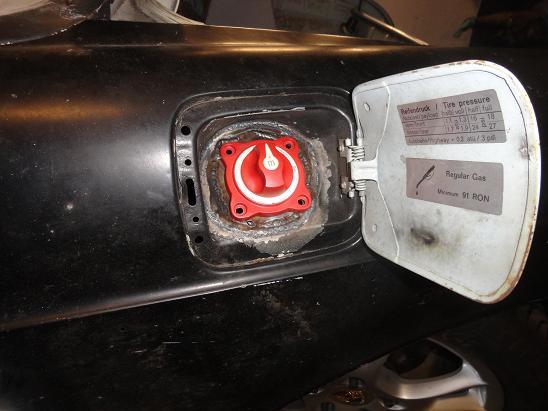
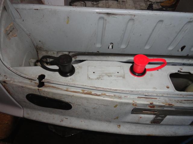
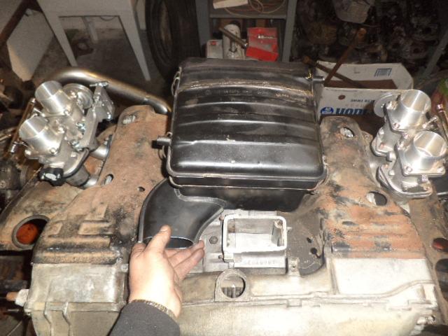
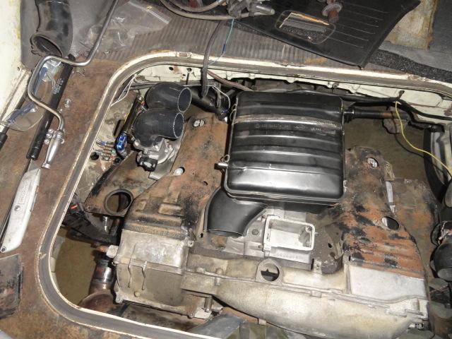
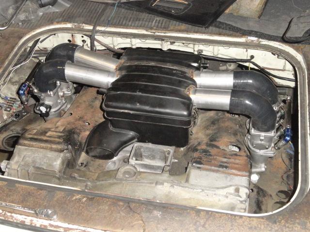
 At least my mods will all be functional. . . I'm keepin' a tight lid on this until they are finished. . .


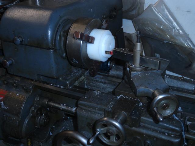
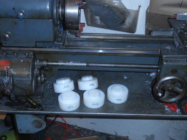
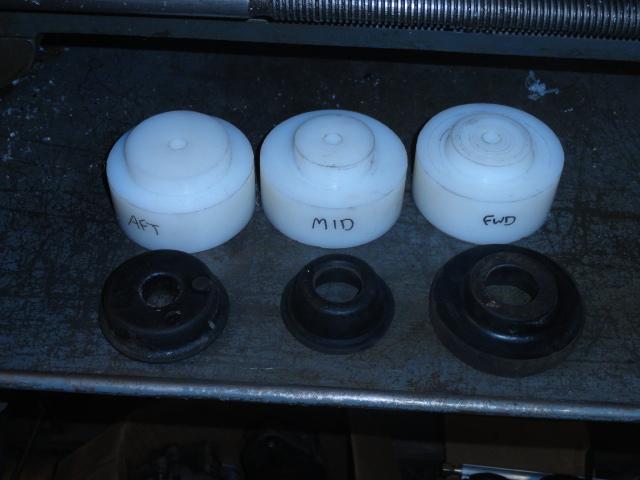
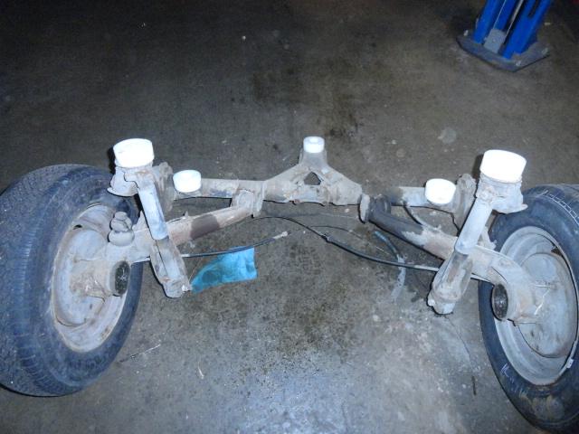


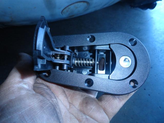
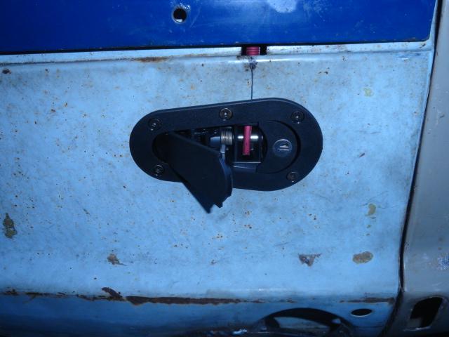
 Money down the tubes. . . obviously!


 Please keep going , very interesting thread as in the past I let 2 squares slip away from me and have always liked them .
 Just wow!!