Help - Search - Members - Calendar
Full Version: I was given a Metal Lathe.
914World.com > The 914 Forums > 914World Garage
Pages: 1, 2, 3, 4, 5
porschetub
[quote name='Mueller' post='2285347' date='Jan 5 2016, 09:23 AM']
[quote name='Series9' post='2285343' date='Jan 4 2016, 12:14 PM']
[quote name='veekry9' post='2285327' date='Jan 4 2016, 02:19 PM']

The machine you have for cheap must be supported by the acquiring of tools of telemetry,500$ basically to start.
Electric drills and saws may be your experience to date,and if so,a period of training is needed,because it's the right thing to do.
smile.gif

[/quote]

So funny but not ,the same thing happened in our machine shop the apprentice started the lathe with 3 jaw chuck key in and the guy next door wore it in the nose,blood everywhere...he had a few days off to recover.
Seen some nasty accidents with hot swarf (turnings) sticking to faces or people clearing swarf and receiving nasty cuts to the bone,this stuff can be very hot and super sharp.
Enjoy your lathe ,there is so much you can do with them,but safety is foremost
veekry9
Well,a trick to the key is:
Every time you engage the spindle,

"Say Key Please"

rhymes with "say cheese please".
Getting a chuck key in the eye is a harsh first lesson.
Danger will robinson,Danger.
Series9
QUOTE(veekry9 @ Feb 10 2016, 01:57 AM) *

Well,a trick to the key is:
Every time you engage the spindle,

"Say Key Please"

rhymes with "say cheese please".
Getting a chuck key in the eye is a harsh first lesson.
Danger will robinson,Danger.


There's something I can use. I don't respond to 90% of your posts because most are so far beyond my current skill level that I just say WTF.gif

I have walked up to the lathe and witnessed the key in the chuck and then thought about the consequences. hide.gif
veekry9
Click to view attachment

Try this,turn your crossfeed handle into the tailstock or chuck(off).
Be certain neither of those immovable objects move.
Use medium pressure.
With a felt pen ,mark the dial at 0.
Gently,turn out until you get movement indicated.
Read off the difference,that is your backlash clearance on the crossfeed acme screw.
0.005" is like new,0.030" is buggered,the crossfeed saddle must be linear in movement to .0005".
Don't worry,it,the aluminum-bronze threaded crossfeed nut may be replaced or repaired.

https://en.wikipedia.org/wiki/Trapezoidal_thread_forms

Fun isn't it?
jd74914
They actually make self-ejecting keys; the machine shops at school have them to keep kids from throwing keys. They are the most frustrating things in the world when you're trying to delicately clamp something though. laugh.gif

http://www.ebay.com/itm/like/181249515436?...=ps&lpid=82
veekry9
See?
Someone is always coming up with a better mousetrap.
Not once did the idea come to mind,because we always remove it before turning.
An idiot proof chuck key would be a hot seller.
Kudos.
nathansnathan
When I first got my South Bend, it was a whole new experience for me as I'd only used production lathes with carbide insert quick change tooling and cnc controls - it's very different with a home lathe using hss bits that can be sharpened. I often use the 4 way switching tool holder seen below. Sometimes the old school tool holders can be more versatile, but I can only use 1/4" bits that way, where the 4 way can handle 3/8" bits.

The most important aspect to forming bits is the end clearance angle. If there is not enough, the tool will ride on the part, bit gets hot and dulls quick. Too much angle and you also have a bit that will dull prematurely.

IPB Image

It's helpful to get preformed bits if you're just starting out. It gives you something to go by, just grind the same shape further down the bit.
http://www.mcmaster.com/#lathe-bits/=112bdwg

Parting is the hardest operation. The trick is flood coolant.

My 1931 south bend.
IPB Image

veekry9
Nice condition.
smile.gif
Series9
QUOTE(veekry9 @ Feb 10 2016, 09:13 AM) *

Try this,turn your crossfeed handle into the tailstock or chuck(off).
Be certain neither of those immovable objects move.
Use medium pressure.
With a felt pen ,mark the dial at 0.
Gently,turn out until you get movement indicated.
Read off the difference,that is your backlash clearance on the crossfeed acme screw.
0.005" is like new,0.030" is buggered,the crossfeed saddle must be linear in movement to .0005".
Don't worry,it,the aluminum-bronze threaded crossfeed nut may be replaced or repaired.

https://en.wikipedia.org/wiki/Trapezoidal_thread_forms

Fun isn't it?


I tried this a few times. I would say mine has about .010" or so.
mbseto
QUOTE(jd74914 @ Feb 10 2016, 09:18 AM) *

They actually make self-ejecting keys; the machine shops at school have them to keep kids from throwing keys. They are the most frustrating things in the world when you're trying to delicately clamp something though. laugh.gif


My drill press came with one of these. It made my brain itch. After much thought I took it apart and removed the spring for this reason: I don't ever want to be in someone else's shop without a strongly ingrained habit of removing the chuck key.
Series9
Here it is! My first part to go into service. It's a custom hub spacer for a T34 swing-axle car that has T1 rear brakes.

Yes, it took me 4.5 hours to make.

What did I learn?

Start with a piece of metal that's as close to the finished size as possible.

The 1.75" OD on this started as a "free" 3" solid piece of round stock.
Series9
Installed:

Darren C
Not bad attempt there Joe,

Watch the outside diameter.
Original bushes are precision ground to a fine micron finish where the lip seal runs.
A turned finish using a HSS tool with coolant will not be good enough.
It'll wear the lip seal within a few miles and your brake hub will be full of oil.
Series9
QUOTE(Darren C @ Feb 17 2016, 05:04 PM) *

Not bad attempt there Joe,

Watch the outside diameter.
Original bushes are precision ground to a fine micron finish where the lip seal runs.
A turned finish using a HSS tool with coolant will not be good enough.
It'll wear the lip seal within a few miles and your brake hub will be full of oil.


After that amount of time at the lathe, we are not calling this an "attempt".


I polished it before installation. We'll see how it goes.

At least the brakes work correctly and the axles turn smoothly.


I'm looking into carbide and ceramic bits. I would definitely like to turn something that comes out like it was polished in the lathe.

I did discover that turning slowly works better for larger bites during the rough process, and spinning the piece quickly for a light pass produces a nicer finish.
r_towle
I think the clock is really the first production piece
Series9
QUOTE(r_towle @ Feb 17 2016, 06:10 PM) *

I think the clock is really the first production piece


It's not yet a clock and it doesn't contribute to the operation of anything. It is simply a reminder to me that the lathe is much more complicated than it appears. beerchug.gif
r_towle
Well, keeping time is important.

I think it's pretty cool you made a custom part for a client, well done go have a beer
Series9

Here are my tail stock parts.

I don't see a way to mount the drill chuck. Is this called a Morse Taper?

What size is it? I need to find the piece to mount the chuck in the tail stock.

nathansnathan
You need an arbor that goes from morse taper to jacobs taper probably. Looks like morse taper 3 from here. Here's a link to some dimensions you can check to be sure
http://littlemachineshop.com/reference/tapers.php

Some chucks are threaded, too, though.
here's the page at mcmaster-carr

http://www.mcmaster.com/#drill-chuck-arbors/=116h0wj
r_towle
threaded chuck?

Rich
Series9
QUOTE(r_towle @ Feb 18 2016, 11:48 AM) *

threaded chuck?

Rich


Negative.

Series9
It looks like the tail stock is an MT3. The numbers don't match the chart exactly, but pretty close.

The drill chuck, however, doesn't really match any of it. It does appear to have a taper that's about 1" long and about .670" at the big end.
Darren C
From the pictures it looks like you need a Morse to Jacobs taper spindle as Nathan also thought.
My advice is swap the chuck for one that takes a Jacobs key. The self locking chuck like you have are great in a hand drill, not so good in a lathe. You cant tighten them up very well and then they can "work-lock" and then you cant get the darn things undone.
nathansnathan
Sounds to me like mt3 to jt6, which is "2811A37" part number at mcmaster.

IPB Image
Series9
QUOTE(Darren C @ Feb 18 2016, 04:07 PM) *

From the pictures it looks like you need a Morse to Jacobs taper spindle as Nathan also thought.
My advice is swap the chuck for one that takes a Jacobs key. The self locking chuck like you have are great in a hand drill, not so good in a lathe. You cant tighten them up very well and then they can "work-lock" and then you cant get the darn things undone.


I think I agree with that. This chuck looks and feels really nice, but there are no numbers on it (I mean no identifying marks of any sort) and it might be good for light duty work, but I can see how it could get stuck.

Shopping for MT3 keyed tail chuck....
Mueller
Nice, making chips and a part for a project car even better!


Porsche930dude
my brother just got a little 6" atlas . its smaller than he wanted but it was cheap. he rebuilt it and is starting to make stuff now. he's been watching utube videos for years so he knows alot. weve been melting aluminum down and making soup can ingots to turn down into stuff. he already made a 4 slot pulley that the lathe was missing now he is going to attempt to make some gears that its missing. He hasnt tried turning steel yet I think hes a little afraid
Darren C
QUOTE(Porsche930dude @ Feb 19 2016, 03:15 AM) *

my brother just got a little 6" atlas . its smaller than he wanted but it was cheap. he rebuilt it and is starting to make stuff now. he's been watching utube videos for years so he knows alot. weve been melting aluminum down and making soup can ingots to turn down into stuff. he already made a 4 slot pulley that the lathe was missing now he is going to attempt to make some gears that its missing. He hasnt tried turning steel yet I think hes a little afraid


40 years ago when I was at school my metalshop teacher (who inspired me to go into engineering) said to the class...

"The lathe is the only machine created by the hand of man that can reproduce itself"

I went on to build my own lathe between age 14 & 16 as my project for my "o level in mechanical engineering workshop theory & practice" I made the headstock, tailstock and carriage in wood, cast it in aluminium using sand boxes and then used the school lathe as a mill. I turned everything, I made the chuck, lead screw, saddles, tool holders...absolutely everything.
It was about a 3ft long when finished and powered by clamping in a hand drill into the basic gear box that I'd made.
Very crude looking back; but hey I was only a kid making his first lathe.
Series9
Will someone explain the different uses for these different angles?

Darren C
It’s all to do with available clearance between what your turning and the position of components of the lathe.
Most standard tip tools are design to sit in one position (90 degrees to the lathe centre) in this normal position the angle of the tip is optimised to turn down or face off.
If you have a rotating tool post you can fit several tools and spin it in 90 degree increments to change between say a parting off tool and a facing off tool. The clamp mechanism allows a small say 10 degree misalignment from North, East, South, West positions where you can clamp it correctly. However if you try and set it a 45 degrees (NE) for example, the clamp device doesn’t lock correctly and the tool will be off Height.
It’s always good practice with a tip tool (particularly with radius end tools) to change the angle slightly between jobs so that it’s not cutting on the same point all the time.
Different finishes can be achieved with different tool angles. (These are angles in the horizontal plane and can be described as angle of attack)
Different angles in the vertical plane (called “Rake”) come into play with HSS tools especially with differing materials. On a soft material such as aluminium you need a larger rake angle than for steel.
Large radius ended tools of HSS are commonly used for a fine smooth shiny finish
Tipped ceramic tools tend to be pre manufactured by material type where best speed and material are specified.
This begins to get complicated when you adjust the tool slide to produce tapers or to reach around the job to gain access to turn awkward shapes, turn with the lathe spinning in reverse or Left hand turn. That’s why you can buy tools with various position tips in the holder. It’s to optimise the angle of attack that the tip of the tool makes contact with the job under various positions and types of RH or LH turning where the tool post angle is not at 90 degrees to lathe centre.
That said some angles of attack vary dependent on the material they are designed for in addition to having differing rakes.
All of this means nothing if you don’t have the correct speed and feed for the material.

Looking at the photo from left to right; the 6 tools run RH, LH, LH, Universal, RH

Hope this is of help.
Series9
Good information. Thank you.

I think I understand angle of attack, but I need more on rake. While I understand the rake plane, what is an example of zero rake vs high rake?

Does the tool always intersect the piece at the 270 degree point in the rotation? (270 being the point that represents west if you look at the chuck end-on).


Also, when you say Right-hand and Left-hand, is that a reference to the direction the tool is moving against the piece or the direction the piece is spinning in the lathe?

I'm under the assumption that almost everything is turned in a CCW direction at the chuck.
veekry9

https://www.youtube.com/watch?v=vAo0xmDQ-kI


https://www.google.ca/#q=turning++4130+shaft
https://www.google.ca/search?q=turning+4340...bEaDPIQ_AUIBigB
http://www.weldingtipsandtricks.com/welding-4130.html

Machining Fundamentals
https://www.google.ca/search?q=Machining+Fu...EM_xr18tvY8M%3A

The design of the lathe makes the CCW rotation load the the toolpost and carriage in compression.(pushing down)
For similar CW loads a secondary toolpost can be installed on the other side of the CL.
As an example,during the '70s while using VDF engine lathes,a shaft similar to the one in the ytub above was ruf turned in conventional
ccw rotation using all 6 corners of the indexing toolpost,heavy production turning.
http://www.carboloy.com/company.html
Subsequently,the final finishing passes were turned with a cw rot and the hydraulic tracing attachment installation,whereby the carriage radius was servo controlled.
A 1:1 scale template was held in sync with the actual shaft and guided the rear crosslide with several paths to the correct dimensions.
The point of all this is that every year since,there has been progress in materials and methods and a steep learning curve is needed to 'bone up'.
Basic,elementary concepts are easily available freely,worthwhile study for the proper use of the machinery.

A horror story:
In 1979 a recently purchased cnc mill was programmed to zig instead of zag by an error of polarity,negative,not positive.
The 7/8" drill in the spindle,about a foot long,snapped off at the shank and struck the operator,the shop owner,between the eyes at the bridge of his nose.
He fell to one knee,hand over his face then staggered to his feet,a golf ball sized lump swelling on his face.
I got him an emergency ice pack from the freezer,and he left for a few days off.
What I mean is,is that even expert machinists make mistakes,had the broken drill penetrated his eye,it would have been fatal.
The energy needed to break the drill and travel the 20-30 feet after striking him,was from the rapid travel rate of the mill and the M42 steel strength of the drill.
Prepare yourself for the proper use of machine tools,period.
Exercise caution and due diligence and read the manuals,warnings and safety notices.
Never run the machine without safety glasses or masks.
Never.

/
ref.
http://www.ebay.com/itm/20-x-157-VDF-S500-...wAAAOSwstxVQ8sM
Click to view attachment

Click to view attachment

https://www.google.ca/webhp?sourceid=chrome...dit+II+cnc+mill
https://www.google.ca/search?q=lathe+tool+g...-lXnx3BrxfKM%3A
http://www.metalsdepot.com/catalog_cart_view.php?msg=
http://www.ingersoll-imc.com/en/index.htm
https://www.google.ca/search?q=carbide+inse...gB&dpr=1.75
/
The industry is so vast that learning the right question is in order.
The grinding of HSS and brazed carbide tools is a whole subject in itself,safety paramount.
Learning to sharpen drill bits to a tested standard is a part of a machine trade training course.
Turning a simple shaft to +/-0.0003 was demonstrated,the experience evident.
Simple errors would get it wrong and useless,making scrap for double or triple loss.
Safety errors cost more than money. unsure.gif
/
https://www.youtube.com/watch?v=otifkak5RMA
/
Good stories of success by innovation and effort.
Just when you think you learned something new,something new must be learned.
The RH,LH refers to the offset of the tool's shank,ie:a left moving tool has a RH offset shank.

http://www.cmsna.com/blog/2013/01/history-...ncept-was-born/
http://www.practicalmachinist.com/vb/cnc-m...er-tape-174794/
https://www.cncci.com/resources/tips.htm
http://www.fadalvmcparts.com/history.html
http://www.haascnc.com/home.asp#gsc.tab=0
http://www.heidenhain.com/en_US/products-a...s/cnc-controls/
http://www.fanucamerica.com/
http://w3.siemens.com/mcms/mc-systems/en/a...k-controls.aspx
http://www.toshiba-machine.com/departmentlanding.aspx?dept=2
http://www.fidia.it/en/prodotti_en.htm
http://www.selca.it/index.php?id=selca
http://www.gruppoparpas.com/products.aspx
http://www.fptindustrie.com/en/products/boring_machines/3/
https://cache.industry.siemens.com/dl/files...13_en_en-US.pdf
https://cache.industry.siemens.com/dl/files...annig_Guide.pdf

Information Overload.
There is so much data to absorb,a small step approach can be effective.Training is crucial,if only for the safety lessons.
Buy a programmable calculator to do the formulas for feeds/speeds/hp/ruf-rms/,just to be in the ballpark,on the same page.
https://www.google.ca/search?q=programmable...SUw0c1UIRqdM%3A
An actual 'real' tool grinder is needed to prepare hss or brazed carbide tools for turning,with the correct abrasive wheels.
Learning of the proper terminology and functions of the lathe controls and components is step #1.
Cutting rates are the next subject,tool geometry the next after that and so on.

/
http://www.cnccookbook.com/MTCNCDictDeflecttoFollow.htm
A good single source of info,handy helpful references for machining.
/
Darren C
QUOTE(Series9 @ Feb 20 2016, 10:43 PM) *

Good information. Thank you.

I think I understand angle of attack, but I need more on rake. While I understand the rake plane, what is an example of zero rake vs high rake?

Does the tool always intersect the piece at the 270 degree point in the rotation? (270 being the point that represents west if you look at the chuck end-on).


Also, when you say Right-hand and Left-hand, is that a reference to the direction the tool is moving against the piece or the direction the piece is spinning in the lathe?

I'm under the assumption that almost everything is turned in a CCW direction at the chuck.


Rake angle is adjustable dependent on the metal, most metal can be cut like wood does with a plane. The shavings curl off the wood if a sharp plane is used in long continuous shaving pieces to leave a smooth finish. With a soft metal a larger rake angle tool tends to do the same. Harder metals can be too hard to cut with "shavings" without immense speeds and pressure, so the rake angle is less and they cut with "small chips" not shavings...This is the best way I can think to explain it to you at the moment.
RH & LH is the direction the tool takes not the rotation of the lathe. Normal turning is RH where the tool travels towards the chuck. LH is where the tool starts near the chuck and moves away from it.
99% of stuff is turned with the CCW direction, but for access reasons or some awkward shape piece there is the ability to reverse the rotation. This is also very common when thread turning.

I'm still concerned for you....

Operating a lathe is a little like flying an airplane.....you can ask 1000's of questions, watch multiple films and read 1000's of books.....but when you start you really need someone by your side to stop you making dangerous mistakes, watching over your shoulder to guide you and prevent things going wrong before they do.

Why don't you contact your local school or college and see if you can enroll in some basic class for turning...you seem like a switched on guy and I think a few hours with a tutor would be great for you.
Series9
QUOTE(Darren C @ Feb 21 2016, 03:34 AM) *


RH & LH is the direction the tool takes not the rotation of the lathe. Normal turning is RH where the tool travels towards the chuck. LH is where the tool starts near the chuck and moves away from it.


That is backwards to me. If the tool is traveling toward the chuck, it's moving to the left. Why would that be RH?

I'm happy that came up, because the directions you put on the tool picture I posted seemed backwards.

And again, please give me a simple explanation of "high rake". I assume zero rake would be directly perpendicular to the piece. Is high rake tip up?

I would love to go take a class, but I've spent hours trying to find one in Central FL and have come up empty. All the tech schools have shifted to IT and no longer offer machine classes of any sort.


As for the flying comment, I'm an 8000-hour jet captain and firmly believe flying a 172 only on book knowledge would be easier and safer than trying to learn this lathe without previous experience.

.....but I will.
Darren C
LH & RH tools and examples of where they are used.

IPB Image

Rake angles (side and back rake)

IPB Image
Series9
QUOTE(Darren C @ Feb 21 2016, 02:09 PM) *

LH & RH tools and examples of where they are used.

IPB Image


That is the single, most useful piece of information I have been given.

From basic observation, I still think LH and RH are reversed, but if that's how it is, then that's how it's is.

LH tools move right and RH tools move left. Okay.


The rake angle diagram, however, actually made things worse.

Simply show me an example of a high rake tool and a zero rake tool, please.


I appreciate the contributions to this thread very much, but you guys are seriously mixing PhD-level lathe processes with middle-school, with high-school, with 2nd grade....

Right now, I'm in lathe Kindergarten. Let's keep it on that level for the moment. I've always been a quick study, but I didn't start my flying career by sitting down in a jet.

smile.gif

Series9
More questions:

How do you run a finishing pass with this tool if you need to complete the pass at a 90* angle on the right side of the pass?

A good example of the need to do this would exist on crankshaft main journals.
Series9
The direction of travel on this makes no sense to me.

Do you have to set it up so the cutting surface is precisely parallel to the intended finish?

How do you begin the cut? Do you move the tool in to full depth and then move it to the face to start cutting? That scenario would require a lot of tool surface cutting all at once.

It seems like you would move the tool from the outside toward the center.
veekry9
Scope,
the overall scope of the task at hand is knowing the the machine will hurt you if not operated correctly,as I've pointed out.
Evidently,a new career in shafting is not in the plan,but obviously if the standards of reference are unknown to you,the links have all the info available.
And yes,everyone who has taken the curriculum has asked the why of the LH/RH question,it's good that you asked.
I believe it came about a few hundred years ago at the very beginning of the 'industrial revolution',while turning bronze cannons,by hand.
The tools were used in a way similar to wood spindle makers,the tool levered to the right hand to turn left,the iron tool shank offset right.
The right hand thread derived it's name from the same roots,the lathe CCW rotating.

Take note that some of the drawings,from 1914 as above,are greatly exaggerated for visual clarity.
The difference between the lh and rh is annoted,for those falling off the turnip wagon.
(A stunt was to draw a face on the back of his head,stumping some beginners!)

http://www.nist.gov/
http://www.nspe.org/
http://www.astm.org/
http://www.sae.org/
https://www.ansi.org/
https://en.wikipedia.org/wiki/BSI_Group
http://www.iso.org/iso/home.html
https://en.wikipedia.org/wiki/Metric_(mathematics)
https://www.google.ca/webhp?sourceid=chrome...-8#q=metallurgy
https://www.google.ca/search?q=involute+spl...fuID7UQ_AUIBigB
https://www.google.ca/search?q=involute+spl...h&q=splines
http://bbs.homeshopmachinist.net/threads/6...nvolute-splines
https://www.google.ca/search?q=thread+turni...1URScmeD2ycM%3A
https://www.google.ca/search?q=lathe+tool+r...zPDxLma0rFDM%3A
http://www.amazon.com/Eshbachs-Handbook-En...r/dp/0470085789
http://www.sandvik.coromant.com/en-gb/pages/default.aspx


Here is a demo of the spline or involute gear forms possible on your lathe.
And how he did it,a most useful idea,though an additional heavy disc brake would ensure the stability of the chuck.
https://www.youtube.com/watch?v=lqreWsmXG4k
https://www.youtube.com/watch?v=BgGXQUeYNKw
Yes,I used this technique recently a few years ago on a heavy 12' X 8' 20T platen.Broaching or shaping by cnc,a keyway or spline into a stationary bore.

I also like the RC heavy equipment he built.
https://www.youtube.com/watch?v=rt8VfgfWa54

The answers to the most basic questions are on page 2 of the manual. idea.gif
https://www.youtube.com/watch?v=Hjsfs49SRbc

/
veekry9
Dedicated tooling and machinery,expressly for the manufacture of crankshafts.
A manual lathe can be used,however,it is a long laborious and expensive process of many steps.
The tools are designed for their single purpose,hence the designation of their names.
The toolpost on the lathe must be indicated to index true,the tooltip must be at the vertical centerline of the shaft.
While threading shafts,the compound slide must be set at the correct angle and zeroed.
The stops must be set to avoid crashes,the speeds and feeds calculated beforehand.
The correct operation of the lathe's feedscrew and halfnut phase dial must be known.
The use of the headstock gearbox also must be understood.
Boring tubes and holes is a primary task,broaching or scraping rifling grooves another.
Drilling deep holes,undercutting and relieving bores is more.
Heavy grooving tools are the methods traditionally used to ruf out crank billet bars.
Offset and steadyrest turning and grinding of cranks is a whole science and skillset by itself.
A 4340 forged 16' X 5' stroke marine crank was done a decade ago in the shop,from scratch to ground finish.
Many tons of chips made,without error,a thing of beauty,by one guy,who had survived a bad accident in '04.

https://www.google.ca/webhp?sourceid=chrome...fts&tbm=vid
https://www.google.ca/webhp?sourceid=chrome...rge+crankshafts

Some useful drops of info,the iso tooling from Walter is just what you might need.
Other vendors sell competing tools too,so buy the lowest price possible.
As mentioned earlier,the hss and brazed carbide tooling is cheap,but requires expert grinding to achieve good results.
These tools,with the quickchange holders,will have you up and running in a jiffy,painlessly.
Jurassic,some retro tools for the small hobbyist user,making the choice easy.

https://www.google.ca/webhp?sourceid=chrome...%20and%20speeds
http://www.walter-tools.com/en-us/tools/st...es/default.aspx
http://www.jurassictools.com/store/tools-engineering-etc

/
Walter:external::screw type:
http://waltertools.blaetterkatalog.de/gc2012/en/#page_A80

/
https://www.youtube.com/watch?v=7cXBXewS4IM
/
veekry9
A trip to the wreckers,an old rusty crank brought to new life by dirty '30s tech.
A little pickle to remove the rust,then a shoestring polish.
All of this came from before,the T Fords and babbit bearings.
This low level flying,or retrotech can be applied to your VW crank if you are looking to stroke for a larger displacement.
A few passes of weld,turning and grinding,and presto,a piece of work.For the all hands on deck type of machiner.

https://www.youtube.com/watch?v=j7DZxqPUQto
http://175.103.60.140/globalindo/carbon-st...cst60aisi-1045/
An entire industry was built out of this,this enterprising approach to the make it better cheaper and faster equation.
biggrin.gif
http://www.hotvws.com/catalogs-2013/2/
/
https://www.youtube.com/watch?v=6lfpip4u-pA

/
Darren C
QUOTE(Series9 @ Feb 21 2016, 11:02 PM) *


I appreciate the contributions to this thread very much, but you guys are seriously mixing PhD-level lathe processes with middle-school, with high-school, with 2nd grade....

Right now, I'm in lathe Kindergarten. Let's keep it on that level for the moment. I've always been a quick study, but I didn't start my flying career by sitting down in a jet.

smile.gif


You're most welcome,
When I get home from Work this evening I'll take some pictures of some of my lathe tools to explain "rake angle" and post them.

In the meantime, my worry is that a loaded gun left in Kindergarten is just as likely to harm as one left in high school in naive or untrained hands.
veekry9
http://www.914world.com/bbs2/index.php?sho...73101&st=52

The details of the'Hopping Herbert'is entertaining to some degree.
Must have been late'70s,an aquaintance of the shop owner,looking for work,I suppose the music biz not panning out.
A simple collet chuck turret lathe series of operations.
https://en.wikipedia.org/wiki/Oxygen-free_copper
Copper alloy bar 1-1/2"dia X 20'length.
Well,neglecting to clamp the barfeeder clamps,the bar,unencumbered,began flapping around the back end of the heavy lathe.
From the other side of the shop,I saw the heavy'wire'create a giant spiral whipping about at high rpm.
Crossing the plane of the whirling,hopping mass,I stopped the spindle,again.
The unbalance of the unique creation had been lifting the Herbert almost a foot,noisily.
When I released the collet,the Danish bun looking thing came out without breaking,the plasticity of the material saving us.
Had it broken,the spinning wheel would have raced around the shop wreaking havoc at 1200 rpm.
Needless to say,that ginger was frozen in fear,the ashen pale look on his face said incomprehension.
A common household 12ga wire might show the same results if spun up in a hand drill.
/
Safety:
Brings to mind the'starting plane',that,which is directly in line with the chuck and work.
Always stand clear of the projectile plane,when starting the spindle,ensure no tools can fall off into the spinning chuck or work.
A place for tools is in safe areas only,secured.
Make a box for them as required.
/
Darren C
Ok……home from work now.....

Lets get down to basics….

There are 6 important angles to understand on a simple HSS lathe tool. The best illustration I can find is this.

IPB Image

Looking down on the tool you have front and side cutting angle. This relates to cutting in line with the lathe or across it (turning down or facing off).
These angles can be set or fixed by grinding the tool or by clamping the tool post at differing angles.

Back rake and side rake are in the horizontal plane and I think were the ones perplexing you? These refer to the top surface of the tool. It can angle downwards to left or right (side rake) in LH or RH tools and angle back towards the lathe operator (hence back rake angle)

Side relief and front relief are in the vertical plane, and hopefully self explanatory in the picture above.

I have been making lathe tools for over 40 years and I’m a qualified toolmaker for my sins, yet I'm still learning stuff. Here’s a few home made basic samples in “proper” High Speed Tool Steel.

IPB Image

This is what good old fashioned HSS lathe tools should be like.

IPB Image

The tool steel is purchased as a bar (far right in photo) and you precision grind it by hand, sometimes to within + or – 1 thousandth of an inch where the rake angles are hand ground to minutes of degrees.

Today however these skills are lost and most lathe users are NOT tool makers, just tool sharpeners and the majority are blissfully unaware of what a true tool maker can do. Most HSS lathe tools today are like this….

IPB Image

Only a small amount of quality HSS is brazed or welded into a poor quality steel holder. The tip is only HSS. These come in all shapes and sizes. But fundamentally they’re pre made so you don’t need to grind any angles or profiles, just dress them on a stone to keep them sharp.

I’m not sure what you have with your lathe, but this is just a real basic guide/help for you to understand simple tool shape. The possibilities of shape and angles are limitless. Understanding what the correct angle on all 6 planes takes years to master and is variable on material, speed and feed.

Hopefully that’s helpful to you for now.

Ceramic or tipped tools are another thing altogether with usually zero apparent back and side rake. Here’s one I set in my lathe tonight to show zero rake.
IPB Image

My advice is start with some basic HSS tools, learn and understand how they work before going on to tipped tools. Plus get yourself on a basic lathe class!
Series9
That is incredibly helpful.

The amount of time you spent on that for me is greatly appreciated.

Thank you.

Series9
I purchased this today.

smile.gif


Series9
This is the tooling that came with the lathe.

I've been operating on the assumption that you "get what you pay for" with this stuff.

I have successfully turned some pieces and I've also destroyed some tools.

I'm not afraid to spend some money on high quality bits. I'm looking at carbide and ceramic.

Darren C
Ok, you got a fair mix there..
IPB Image
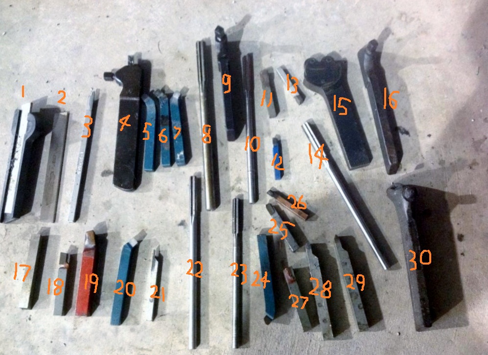
Some are no good, others need work and just a few are useful to you as a beginner. I’ve numbered them so you know which tool I’m referring to.
1. Parting tool HSS and Holder. (very good, keeper. Get it sharp, grind the correct front relief, very tiny side relief and no side rake. A medium back rake will see you through most materials) A very good basic and useful parting tool. As it wears you re-grind and move the HSS steel forwards. ALWAYS set the tip contact with the job at dead centre height or ever so slightly low. NEVER go above centre height.
2. Plain Parting HSS (looks to be too wide for holder 1, you may need another holder for this)
3. Resolution on photo poor, but looks like a badly ground/messed up HSS parting. Cut off re-grind and start again with a suitable holder. (may fit same holder as 2)
4. Including 9, 16 & 30. HSS tool holders for smaller maybe what looks like ¼ or 3/8 HSS. You buy the HSS as in my first photo of the early rake descriptions and grind whatever tool you need. Very good old tool holders worth their weight in gold but too advanced for you for learning without good HSS ground tools to fit them. (keepers. Put them in your tool drawer for the future and get a new locking screw for 30 it looks a little chewed up)
5. Including 6 are RH knife tools profile for bevel turning steel Side & Front cutting angle too steep for straight turning and facing off steel, but ok with brass & aluminium.
7.Including 24 & 20 LH knife tool uses as for 5 & 6 above.
8. Including 10, 14, 22 & 23 Ream tools. I doubt you’ll ever need these.
11. Including 17 from the poor resolution photo look like unground tool steel. (put them in a draw for the future)
12. Including 18, 25 & 26 RH Knife tools. These have better side and front cutting angles for steel but they look well used and poorly re-ground. This is the sort of shape tool you need as a beginner but unfortunately these four look in a poor condition and need grinding work to restore them.
13. Including 27 are LH knife tools but old 13 looks useable as 27 needs a re-grind like your RH knifes.
15. Knurl tool. Good basic tool. Check the wheel spindle pins aren’t worn and the wheels are firm and don’t wobble or side in the shaft as any movement will make for a "double" inprint knurl. Plus also check the knurl profile is sharp. They do get worn down over the years and then they’ll be no good.
19. RH facing tool, looks badly ground on top surface back and side rake. Profile looks ok for facing off, but rakes need re-grind.
21. Including 28 & 29 are HSS thread cutting tools. Again these are not for you at this learning stage, stick them in the drawer for the future.

Overall you have a reasonable selection of tools but none are really up to scratch for using successfully.
Try and find a good machine shop or college nearby, take them in and get someone who knows what they’re doing to re-grind them for you. This shouldn’t cost too much money (may be just a crate of beer) and will be far cheaper than buying carbide/ceramic tipped tools and holders that you’re not ready for just yet.
You only need 1, 18 & 19 to learn with at an early stage.
Good choice on new tool post, very handy for setting tool height easy without shims under tools.
Series9
Fantastic information. Some of the tools have a wax-like protective coating on the tips. That's probably what you're seeing as "poor resolution".
mbseto
This is turning into a pretty cool thread!


(see what I did there?)
This is a "lo-fi" version of our main content. To view the full version with more information, formatting and images, please click here.
Invision Power Board © 2001-2024 Invision Power Services, Inc.