bigkensteele
Jan 25 2013, 07:30 PM
QUOTE(914Eric @ Jan 25 2013, 04:31 PM)

QUOTE(Kirmizi @ Jan 25 2013, 04:13 PM)
Allegedly, popping that cap off was a factory authorized "fix" years ago, to prevent the fuel pump from overheating.

Actually, I think that he is right. I believe that somebody posted a TSB from Porsche detailing the modifications done to your car. So, while not original, they are factory-blessed.
rhodyguy
Jan 26 2013, 12:35 PM
the wadded up aluminum foil (what it looks like to me) around the fuel lines is weird. the air deflector seems wonky too.
k
914Eric
Jan 26 2013, 01:54 PM
QUOTE(rhodyguy @ Jan 26 2013, 10:35 AM)
the wadded up aluminum foil (what it looks like to me) around the fuel lines is weird. the air deflector seems wonky too.
k
Kevin,
Yes it WAS aluminum foil around the fuel lines. and the air deflector was modified to direct air UP into the engine, rather than down. And then of course the aluminum hose connected to the H.E. valve. All will be put back to original. If I run into any vapor lock problems, I'll just move the fuel pump up to the front and solve the problem correctly.
Since I'll be driving in the PNW, and not through the Mojave desert in the summer like my Dad did...I'm hopeful that the vapor lock problem will no longer be an issue.
914Eric
Jan 28 2013, 05:24 PM
OK...so what is the secret for getting the heat exchanger unscrewed from the cylinders?
I got three of the 4 nuts off on the driver side, and Only 2 on the passenger side. The space is so tight that my 13mm socket won't even fit up there.
I'm ready to drop the engine, and this was the last thing to do. Are they easier to get off once the engine is out? Doesn't seem so to me, but I'm a rookie so what do I know.
Thanks in advance guys.
Dave_Darling
Jan 28 2013, 06:23 PM
The trick for me was to use 1/4" drive sockets. They tend to be a little thinner-walled than 3/8" drive ones, and fit slightly better into those cramped spaces. Also, some brands are thinner than others. For instance, I know that a 10mm 1/4" drive socket from Snap-On will fit into a 911 seat rail, while a 10mm 1/4" drive socket from Craftsman will not.
I also used a "wobble" extension as well on the heat exchanger nuts to give me more approach angles. Not sure that I actually needed it, but I had one on hand.
--DD
JeffBowlsby
Jan 28 2013, 06:38 PM
QUOTE(Kirmizi @ Jan 25 2013, 04:13 PM)
Allegedly, popping that cap off was a factory authorized "fix" years ago, to prevent the fuel pump from overheating.
True. Using asbestos cloth on the fuel lines, not aluminum foil.
http://bowlsby.net/914/Classic/zSB_1973-10-06_P213.pdf
914Eric
Jan 28 2013, 07:18 PM
QUOTE(Dave_Darling @ Jan 28 2013, 04:23 PM)
The trick for me was to use 1/4" drive sockets. They tend to be a little thinner-walled than 3/8" drive ones, and fit slightly better into those cramped spaces. Also, some brands are thinner than others.
--DD
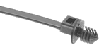
You're the Man Dave! 1/4 drive fit right up there. Came off nicely with the exception of one exhaust stud which came out.
So should I use some RED LockTite when I put the stud back in, or is there a better way to keep it from coming out?
Click to view attachmentClick to view attachment
bigkensteele
Jan 28 2013, 07:30 PM
QUOTE(914Eric @ Jan 28 2013, 05:18 PM)
So should I use some RED LockTite when I put the stud back in, or is there a better way to keep it from coming out?
If anything, you should use anti-seize. Exhaust studs/nuts/heads are notorious for stripping and or breaking. Better that the stud comes out of the head than breaking off.

914Eric
Jan 28 2013, 07:37 PM
QUOTE(bigkensteele @ Jan 28 2013, 05:30 PM)
QUOTE(914Eric @ Jan 28 2013, 05:18 PM)
So should I use some RED LockTite when I put the stud back in, or is there a better way to keep it from coming out?
If anything, you should use anti-seize. Exhaust studs/nuts/heads are notorious for stripping and or breaking. Better that the stud comes out of the head than breaking off.
Yea...Great point Ken...Thanks...I don't know what I was thinking.
That's why I ask a lot of "Stupid" question and think out loud on here. For a hobby mechanic, it's real easy to do something dumb.
bigkensteele
Jan 28 2013, 07:47 PM
QUOTE(914Eric @ Jan 28 2013, 05:37 PM)
QUOTE(bigkensteele @ Jan 28 2013, 05:30 PM)
QUOTE(914Eric @ Jan 28 2013, 05:18 PM)
So should I use some RED LockTite when I put the stud back in, or is there a better way to keep it from coming out?
If anything, you should use anti-seize. Exhaust studs/nuts/heads are notorious for stripping and or breaking. Better that the stud comes out of the head than breaking off.
Yea...Great point Ken...Thanks...I don't know what I was thinking.
That's why I ask a lot of "Stupid" question and think out loud on here. For a hobby mechanic, it's real easy to do something dumb.
The only stupid question is the one you don't ask, and then make a mistake as a result.

We have all been in the same boat that you are in now, and I can't speak for everyone, but I enjoy imparting what little knowledge I have on others. Even the old-timers here were newbies once. Except for the Cap'n.
Kirmizi
Jan 28 2013, 07:59 PM
Looks like one copper gasket is still on the passenger side HE, did you remove the other three from the heads?
nathansnathan
Jan 28 2013, 07:59 PM
QUOTE(bigkensteele @ Jan 25 2013, 05:30 PM)
QUOTE(914Eric @ Jan 25 2013, 04:31 PM)
QUOTE(Kirmizi @ Jan 25 2013, 04:13 PM)
Allegedly, popping that cap off was a factory authorized "fix" years ago, to prevent the fuel pump from overheating.
Actually, I think that he is right. I believe that somebody posted a TSB from Porsche detailing the modifications done to your car. So, while not original, they are factory-blessed.
I was going to mention that. I might do this on my car if there is a problem.
http://bowlsby.net/914/Classic/zSB_1973-10-06_P213.pdf
euro911
Jan 28 2013, 08:32 PM
QUOTE(Kirmizi @ Jan 28 2013, 05:59 PM)
Looks like one copper gasket is still on the passenger side HE, did you remove the other three from the heads?
I sure it would have fallen off the HE, but definitely dig out the ones stuck in the exhaust ports.
'Someone' I know had an exhaust leak and we found two copper gaskets stuck up in one of the ports when we removed the HEs

914Eric
Jan 28 2013, 09:39 PM
QUOTE(nathansnathan @ Jan 28 2013, 05:59 PM)
QUOTE(bigkensteele @ Jan 25 2013, 05:30 PM)
QUOTE(914Eric @ Jan 25 2013, 04:31 PM)
QUOTE(Kirmizi @ Jan 25 2013, 04:13 PM)
Allegedly, popping that cap off was a factory authorized "fix" years ago, to prevent the fuel pump from overheating.
Actually, I think that he is right. I believe that somebody posted a TSB from Porsche detailing the modifications done to your car. So, while not original, they are factory-blessed.
I was going to mention that. I might do this on my car if there is a problem.
http://bowlsby.net/914/Classic/zSB_1973-10-06_P213.pdfI'm familiar with the "Recommended Fix". I was laughing because I know it didn't work worth a crap. After this was done, Dad still had problems. Knocking off the cap and adding a hose, and wrapping the fuel lines in tin foil, did not fix the problem.
Like I said earlier, Dad liked to drive the car to the river and Vegas in 110 degree temps, so I'm hoping since Idaho is more 50-80 degrees...It won't be an issue any more.
I think the only TRUE fix is to move the fuel pump up front, and that's what I'll do if this is ever an issue in the future.
914Eric
Jan 29 2013, 03:50 PM
Well...There's 40 years of ugly that needs to be knocked off. Now what? lol
So I'm going to clean and paint the tin, changing fuel lines, and vacuum lines, injector seals, throttle body gasket, major tune up, etc...
OK guys...Here's where I need your inputs: What should I NOT FORGET to do while I have the engine out?
Click to view attachmentClick to view attachmentClick to view attachmentClick to view attachment
bigkensteele
Jan 29 2013, 03:59 PM
You might want to get a complete gasket set and replace everything you can reach. It also comes with new exhaust gaskets, which you willl need anyway.
However, the gasket set will not include viton pushrod tube seals and front and rear main seals. I got mine from Eric Shea.
Take pictures of the markings on your tin holding a ruler by them. That way if you will be able to replicate them with a stamp after you paint the tin.
If I can find my checklist, I will pm it to you.
Dave_Darling
Jan 29 2013, 09:25 PM
If you're going to pull the flywheel off for any reason, epoxy over the oil gallery plugs on the back of the motor. If you're going to pull the fan shroud off (probably a good idea if you're painting the engine tin) you can epoxy over the gallery plugs up front. After a few decades' worth of heat cycles, they can get a little loose and pop out one cold morning when you start the car.
--DD
914Eric
Jan 30 2013, 08:38 PM
So before I dropped the engine, I was removing the shift linkage and when I removed the plastic cup that surrounds the rear shift linkage it was full of oil...probably a cup. I'm guessing there is a seal of some sorts that seals the shifting arm? Is this an easy fix of something that requires Dr. Evil or equivalent?
Dave_Darling
Jan 30 2013, 09:53 PM
Easy fix. Remove the two nuts that hold the side shift console on. Pull it out of the trans; you will need to tilt it at one point to get the rake to clear the hole in the trans. Drain it first or you'll dump your gear oil when you do this...
Press out the roll pin that holds the rake onto the shaft. (Leave the pin that holds the bottom arm onto the shaft in place.) Slide the shaft out of the console, replace the seal, then put it all back together. Don't forget a new O-ring around the shift console.
--DD
914Eric
Jan 31 2013, 12:42 PM
Ok, so I spent an hour looking through the Parts DVD trying to find the name of this with no luck. I remember seeing a thread about it a couple of months ago, but since I don't know the name of the part, searches gave me nothing.
So what's it called and does anyone remember the thread that this was discussed in?
The rubber is cracked and I need a new one. I seem to remember from the thread that discussed this that they are NLA? Say it ain't so.
An interesting aside is that the top AAR connection was plugged into this part rather than the connection next to the oil filler which means they were switched. I know this because I have a Dave Darling created schematic of the vacuum system that I got from somewhere that has been a BIG help with labeling and understanding where everything goes.
Click to view attachment
Dave_Darling
Jan 31 2013, 01:57 PM
"Stacked Elbow". NLA as far as I know, but Mikey914 was going to make repops of it.
My vacuum diagrams have the two large hoses to the decel valve switched around, BTW.
You can get away with eliminating this piece, hooking the large hose directly to the manifold, then splicing a tee into the vacuum retard hose from the throttle body for the small hose that would plug into the elbow. Not quite optimal, but it will work. Especially in the short term.
--DD
championgt1
Jan 31 2013, 01:58 PM
Stacked vacuum elbow. I do believe they are NLA. I would put up a WTB add here and see if anyone has one laying around.
JawjaPorsche
Jan 31 2013, 04:09 PM
QUOTE(914Eric @ Jan 31 2013, 01:42 PM)
Ok, so I spent an hour looking through the Parts DVD trying to find the name of this with no luck. I remember seeing a thread about it a couple of months ago, but since I don't know the name of the part, searches gave me nothing.
So what's it called and does anyone remember the thread that this was discussed in?
The rubber is cracked and I need a new one. I seem to remember from the thread that discussed this that they are NLA? Say it ain't so.
An interesting aside is that the top AAR connection was plugged into this part rather than the connection next to the oil filler which means they were switched. I know this because I have a Dave Darling created schematic of the vacuum system that I got from somewhere that has been a BIG help with labeling and understanding where everything goes.
Click to view attachmentI think Auto Atlanta sells the stacked elbow:
http://www.autoatlanta.com/Porsche-Stacked...022129637B.htmlHope this helps.
Terry
championgt1
Jan 31 2013, 04:22 PM
I bought one of those. Never again!!! A vacuum elbow is no good when it is "new" and has holes in it!
JawjaPorsche
Jan 31 2013, 04:24 PM
QUOTE(914Eric @ Jan 29 2013, 04:50 PM)
Well...There's 40 years of ugly that needs to be knocked off. Now what? lol
So I'm going to clean and paint the tin, changing fuel lines, and vacuum lines, injector seals, throttle body gasket, major tune up, etc...
OK guys...Here's where I need your inputs: What should I NOT FORGET to do while I have the engine out?
Click to view attachmentClick to view attachmentClick to view attachmentClick to view attachmentReplace air intake manifold gasket and hose. Pelican has them:
http://www.pelicanparts.com/cgi-bin/smart/...20%281973-76%29http://www.pelicanparts.com/cgi-bin/smart/...76%29%2C%20EachAlso paint your air intakes and injector brackets. See picture how it really makes your engine look better. I used heat paint.
JeffBowlsby
Jan 31 2013, 07:26 PM
QUOTE(914Eric @ Jan 29 2013, 01:50 PM)
Well...There's 40 years of ugly that needs to be knocked off. Now what? lol
So I'm going to clean and paint the tin, changing fuel lines, and vacuum lines, injector seals, throttle body gasket, major tune up, etc...
OK guys...Here's where I need your inputs: What should I NOT FORGET to do while I have the engine out?
I rarely self-promote, but you asked...I gotta say your wiring looks marginal at best. I know someone who can make it all better for you...

Free repair quote if you will send it all to me, PM/email me for details. FI harness, Ignition harness, Oil temp sender wire and Alternator harness...check them all over.
JawjaPorsche
Jan 31 2013, 07:36 PM
QUOTE(Jeff Bowlsby @ Jan 31 2013, 08:26 PM)
QUOTE(914Eric @ Jan 29 2013, 01:50 PM)
Well...There's 40 years of ugly that needs to be knocked off. Now what? lol
So I'm going to clean and paint the tin, changing fuel lines, and vacuum lines, injector seals, throttle body gasket, major tune up, etc...
OK guys...Here's where I need your inputs: What should I NOT FORGET to do while I have the engine out?
I rarely self-promote, but you asked...I gotta say your wiring looks marginal at best. I know someone who can make it all better for you...
Free repair quote if you will send it all to me, PM/email me for details. FI harness, Ignition harness, Oil temp sender wire and Alternator harness...check them all over.

Jeff is the best.
914Eric
Jan 31 2013, 09:26 PM
QUOTE(Jeff Bowlsby @ Jan 31 2013, 05:26 PM)
I rarely self-promote, but you asked...I gotta say your wiring looks marginal at best. I know someone who can make it all better for you...
Free repair quote if you will send it all to me, PM/email me for details. FI harness, Ignition harness, Oil temp sender wire and Alternator harness...check them all over.
Jeff is correct in that the wires are all very brittle and some have black tape covering scrapes and breaks. I haven't looked at all the connectors yet but the few I did look at seemed OK.
tod914
Jan 31 2013, 09:31 PM
You'll be more than pleased with Jeff's work. Top notch. Very accomodating. He even sourced the correct color sheathing for me on a previous 914.
zambezi
Jan 31 2013, 10:13 PM
clutch, throw out bearing, adjust valves
rhodyguy
Feb 1 2013, 10:53 AM
i saw the repro stacked elbow championgt1 received from AA. pos, junk ( i warned him
). they wouldn't sell him one of the nos ones they claimed to have in stock. if you buy a repro be sure to save the metal tubes as the repros don't come with them.
tod914
Feb 2 2013, 12:43 AM
What about using a 1.7 elbow. A little different configuration, but should work. NOS ones are still around.
914Eric
Feb 2 2013, 10:23 AM
QUOTE(tod914 @ Feb 1 2013, 10:43 PM)
What about using a 1.7 elbow. A little different configuration, but should work. NOS ones are still around.
I'll look into that Tod...Thanks.
914Eric
Feb 2 2013, 10:33 PM
I got the fuel pump out and all the fuel lines in the engine compartment. Also got the fuel rails and injectors out. I'm trying to make sense of the how it works.
I have 4 questions The "S" suction line on the left coming from the fuel tank is obvious.
The damper "D" line in the middle runs to the passenger side fuel rail, and the factory manual says that it "Sends" out fuel.
1)Why is there a short piece of original plastic spliced between the the two rubber ends? Why not just use one long piece of rubber fuel line?
The "R" line on the right has a splitter with the long piece going to the fuel pressure regulator, and the short piece going to the ruturn line.
2) What I don't understand, is how any pressure can be built up for the regulator to regulate, when there is an open connection splitting off and going into the return line? Seems like that as fast as the fuel pump sends it out, it would just drain right off into the return?
It also seems odd that the "D" line even exists since the two fuel rails are connected after the fuel pres. reg. connects to the driver's side fuel rail?
3) Why not just cap the passenger side fuel rail where the "D" line connects to it?
4) Is this what they did on later models that only use 2 prong fuel pumps?
Thanks as always...and ENJOY the game tomorrow.
Click to view attachment
davesprinkle
Feb 2 2013, 10:44 PM
The third fitting on the pump is the outlet of an internal pressure-relief valve. Under normal circumstances, it will never flow fuel. It only operates if you've got something like a pinched fuel line that causes an over-pressure condition.
Dave_Darling
Feb 3 2013, 12:46 AM
The plastic in the supply line is to go through the engine shelf. There should be an angled grommet in both holes on the engine shelf, and plastic lines should be going through them. The stainless lines that Racer Chris sells (and possibly others) are good replacements for all of the plastic lines.
"D" stands for "Druck", which is German for "Pressure". There is no damper for the fuel, and if you see one on a diagram that would be an error.
The pressure regulator acts kind of like your thumb over the end of a garden hose. It plugs up the return from the high-pressure fuel loop (the fuel rails are part of that) until the pressure in the loop is high enough, and it opens to bleed off pressure over that.
The line coming from the regulator is just a way to dump excess fuel back to the tank. The Y lets the pump also dump excess fuel to the tank.
--DD
914Eric
Feb 3 2013, 01:30 PM
QUOTE(Dave_Darling @ Feb 2 2013, 10:46 PM)
The plastic in the supply line is to go through the engine shelf. There should be an angled grommet in both holes on the engine shelf, and plastic lines should be going through them. The stainless lines that Racer Chris sells (and possibly others) are good replacements for all of the plastic lines.
"D" stands for "Druck", which is German for "Pressure". There is no damper for the fuel, and if you see one on a diagram that would be an error.
The pressure regulator acts kind of like your thumb over the end of a garden hose. It plugs up the return from the high-pressure fuel loop (the fuel rails are part of that) until the pressure in the loop is high enough, and it opens to bleed off pressure over that.
The line coming from the regulator is just a way to dump excess fuel back to the tank. The Y lets the pump also dump excess fuel to the tank.
--DD
Excellent Dave...thanks. For some reason I thought "R" line that ran directly to the fuel regulator was the pressure line and obviously that wouldn't work.
914Eric
Feb 4 2013, 05:57 PM
Pulled the 6 cheesehead screws out to remove the rear engine shield. On the left are the 2 grommets where the Red starter wire, yellow starter wire, and the 2 backup light wires go through.
On the right is the grommet where the black battery connection to the starter goes through and runs above the transaxle being held up with 2 plastic ties that snap into the engine shield. One of the plastic ties is broken. Anybody know if these are still available?
Its hard to see in this picture, but there are two seals that run along the top left and right corners on the inside. Seals and grommets are in surprisingly good shape.
Click to view attachment
914Eric
Feb 5 2013, 12:59 PM
Peeling everything back and trying to document all the wiring. In this photo, it's interesting that the white wire connects to a red wire which runs to the AAR. Seems odd that the colors would switch like that?
Also you can see a green wire with a connector taped down to that same harness that goes nowhere. Hate seeing wires hanging and not going anywhere. Guess it's possible that it was just an extra in the harness from the factory and that is how it was sent out. Seems more likely though that some mechanic along the line left off something that wasn't "Required".
Hmmmm...
 Click to view attachment
Dave_Darling
Feb 5 2013, 03:13 PM
The AAR power wire is part of the fuel injection wiring, so the wire is white. For whatever reason, the wire coming from the AAR itself is red. They all seem to be that way on the D-jet AARs.
The green wire in the distributor harness looks like it has a black stripe. If so, it would be for oil temp, but I don't believe the oil temp wire should be in the ignition harness on a 2.0 motor. Could you have an ignition harness from a 1972 1.7 on your motor? I believe those did have an oil temp wire, even though it was not hooked up to anything.
--DD
914Eric
Feb 5 2013, 03:54 PM
QUOTE(Dave_Darling @ Feb 5 2013, 01:13 PM)
The AAR power wire is part of the fuel injection wiring, so the wire is white. For whatever reason, the wire coming from the AAR itself is red. They all seem to be that way on the D-jet AARs.
The green wire in the distributor harness looks like it has a black stripe. If so, it would be for oil temp, but I don't believe the oil temp wire should be in the ignition harness on a 2.0 motor. Could you have an ignition harness from a 1972 1.7 on your motor? I believe those did have an oil temp wire, even though it was not hooked up to anything.
--DD
The green wire does have a black stripe. I'm almost certain that is the original harness Dave. I traced the Green/black wire back to the relay box. See photo. It is the left side...second connection down. On the back of the relay plug it says it is pin #3. Does that give you any help?
Click to view attachment
Dave_Darling
Feb 5 2013, 10:25 PM
The #3 pin should not be connected in a 73 914. Actually, the only place I see the #3 pin connected is in the 71 wiring diagram, not the 72 one. And it is shown as going to an optional oil temp sensor.
Note that in the 73, the temp sensor wire runs over to the right side of the engine bay and joins into the main wiring harness there.
Looks like you have an oddball ignition harness. Either swapped in by a previous owner, or perhaps the factory using up something that they had on hand.
--DD
rhodyguy
Feb 6 2013, 08:23 AM
eric, those black plastic cable holders are retained with little plastic pins that push out. most times the holders have been cut, rendering them useless. the grommeted clamp like the one pictured will do the trick. hardware store.
McMark
Feb 6 2013, 09:47 AM
McMaster-Carr PN: 6686K21 is the closest thing to the correct zip tie I've seen. But the hole in the tin is slightly too large. If you put a grommet in the hole first it should work. The OE zip ties are also 'removable' so you could replace the cable. These aren't.
914Eric
Feb 6 2013, 11:06 AM
QUOTE(Dave_Darling @ Feb 5 2013, 08:25 PM)
The #3 pin should not be connected in a 73 914. Actually, the only place I see the #3 pin connected is in the 71 wiring diagram, not the 72 one. And it is shown as going to an optional oil temp sensor.
Note that in the 73, the temp sensor wire runs over to the right side of the engine bay and joins into the main wiring harness there.
Looks like you have an oddball ignition harness. Either swapped in by a previous owner, or perhaps the factory using up something that they had on hand.
--DD
Dave...I'm happy to hear that my year and model car doesn't use pin 3. So the fact that it is cut and taped down onto the harness isn't a problem and done at the factory.
Dave, My Dad and I are the original owners so that is how I know the harness hasn't been replaced. After disassembly, it is clear to me that the wiring is original. The way it is brittle and formed. Also still in all the factory ties, cheesehead screws that have never been out...Etc.
My best theory on what is happening is that my car is one of the first 73's with the vinyl windshield posts (Build date of Aug. 72) and that is how they did the harnesses on the early cars until they got the harnesses for the "real" production run.
nathansnathan
Feb 6 2013, 12:26 PM
QUOTE(914Eric @ Feb 6 2013, 09:06 AM)
My best theory on what is happening is that my car is one of the first 73's with the vinyl windshield posts (Build date of Aug. 72) and that is how they did the harnesses on the early cars until they got the harnesses for the "real" production run.
According to Bowlsby's wiring harness chart, 72's weren't supposed to have the green and black one in the ignition harness either - not sure where it would have been in 72 actually?
http://bowlsby.net/914/WiringHarnesses/914...nessIDGuide.pdf
914Eric
Feb 6 2013, 06:03 PM
Another rookie question for you guys.
Temp sensor 1 is in the top of the air distribution box and measures the temp of the intake air.
Temp sensor 2 goes into the head near cylinder 2 and measures engine temps.
What is the thermoswitch, and what is it measuring?
Dave_Darling
Feb 6 2013, 07:28 PM
The thermoswitch on a 2.0 sits on a bracket that sticks up from one of the "feet" holding the manifold (plenum) onto the top of the crankcase. Its function is to provide a ground for the cold-start valve. When the sensor is colder than about 40F (some versions, as low as 32F, maybe lower?) the switch grounds the connector on it to its threads.
The CSV is powered from the same yellow wire that powers the starter, so it only opens up when the starter is cranking and when it is "cold enough".
--DD
914Eric
Feb 6 2013, 07:43 PM
QUOTE(Dave_Darling @ Feb 6 2013, 05:28 PM)
The thermoswitch on a 2.0 sits on a bracket that sticks up from one of the "feet" holding the manifold (plenum) onto the top of the crankcase. Its function is to provide a ground for the cold-start valve. When the sensor is colder than about 40F (some versions, as low as 32F, maybe lower?) the switch grounds the connector on it to its threads.
The CSV is powered from the same yellow wire that powers the starter, so it only opens up when the starter is cranking and when it is "cold enough".
--DD
So then what I'm hearing is that most of the time they do nothing, and then if it's a below zero Idaho morning, only while starting.
Thanks again Dave...I'm going to have to start paying you a retainer.
914Eric
Feb 7 2013, 12:29 PM
Got the front engine tin off and noticed that I seem to have a ground connection with nothing attached. All my wires were labeled and everything seems accounted for so I'm not sure if and/or what attaches to this ground.
If you look below the distributor, surrounded by the green coil wire, you see a cheeshead screw with the connector attached.
The second picture is a closeup with everything removed.
After studying the wiring, I think this is my last "mystery".
Click to view attachmentClick to view attachment
This is a "lo-fi" version of our main content. To view the full version with more information, formatting and images, please
click here.