Full Version: 1973 2.0 Original Survivor
the green wire? fact oil temp sender wire. it is attached to the front of the case and runs behind the shroud.
That metal looks pretty dull as though it hasn't been used for awhile.
I don't recall ever seeing a spade connector there.
Mike
I don't recall ever seeing a spade connector there.
Mike
QUOTE(Kirmizi @ Feb 7 2013, 11:16 AM) 
That metal looks pretty dull as though it hasn't been used for awhile.
I don't recall ever seeing a spade connector there.
Mike
Yea...it is dull and nothing was connected. I just want to make sure that it was never connected...and not something a sloppy mechanic just forgot to connect. although there isn't any wires just hanging anywhere or even cut off. Not sure why the factory would add this ground to the cheesehead screw if it wasn't going to be hooked up to anything?
Hopefully, one of our resident engine gurus can answer this.

Eric, you got me curious so I went out and checked mine, no ground connector there...
Click to view attachment
Click to view attachment
QUOTE(turk22 @ Feb 7 2013, 05:08 PM)
Eric, you got me curious so I went out and checked mine, no ground connector there...
Click to view attachment
Thanks Steve...I appreciate it.
Hmmmm...Not sure what to make of it.
I've seen that a few times, but never seen anything attached to it.
I have this connector on all four of my type 4 engines, never seen anyting connected to it...handy ground point for the test instrument but sure there is another reason...
Lars S
Lars S
So my thermostat is shot...wide open in 40 degree weather. I believe I've read that OEM thermostats are NLA, so what is everyone using now?
Also...I was a little surprised at how the flaps seem to work. In my mind, I expected that when the thermostat expanded, both the flaps would open. My flap linkage seems to be working smooth and properly, and what I'm seeing is that when cold, the driver's side is closed and right side is open. When hot, the driver's side opens, and the passenger side closes. Is this correct?
Click to view attachment
Click to view attachment
QUOTE
So my thermostat is shot...wide open in 40 degree weather. I believe I've read that OEM thermostats are NLA, so what is everyone using now?
This is the only place I know about...
http://www.awesomepowdercoat.com/thermosta...ed_rebuilt.html
Someone on here was repairing them at some point, but i don't recall how, maybe something about compressing them, heating them and then soldering? Other option is to find a good used one, or wire it in the full open position(it will take long to heat up though). I found a working used bellows for mine.
*edit* just checked that link above, looks like a good deal to me.
*edit* just checked that link above, looks like a good deal to me.
A lot of people use a type 1 thermostat instead of the type 4; they're easier to find. It opens at 150F instead of 180F but it works alright. Without a working thermostat, you end up with frothy oil from not ever getting warmed up.
QUOTE(rnellums @ Feb 11 2013, 05:37 PM)
Someone on here was repairing them at some point, but i don't recall how, maybe something about compressing them, heating them and then soldering? Other option is to find a good used one, or wire it in the full open position(it will take long to heat up though). I found a working used bellows for mine.
*edit* just checked that link above, looks like a good deal to me.
There is a guy on Samba selling new ones.
I thin kit's the same guy (same pics, same price)
http://www.thesamba.com/vw/classifieds/detail.php?id=1036746
http://www.thesamba.com/vw/classifieds/detail.php?id=1036746
That wasn't my understanding as to how it worked either. I thought they were both opened or both closed. Not sure I understand why it would matter which side opened, but there may be a reason related to how the tin directs the airflow.
I was under the impression that if the thermostat failed both flaps failed to open...but there are much more experienced folks here to answer that...
thats why I like this thread, everything is directly related to the questions I have as well...thanks for blazing the path for us other newbies Eric!
So my thermostat is shot...wide open in 40 degree weather. I believe I've read that OEM thermostats are NLA, so what is everyone using now?
Also...I was a little surprised at how the flaps seem to work. In my mind, I expected that when the thermostat expanded, both the flaps would open. My flap linkage seems to be working smooth and properly, and what I'm seeing is that when cold, the driver's side is closed and right side is open. When hot, the driver's side opens, and the passenger side closes. Is this correct?
I was under the impression that if the thermostat failed both flaps failed to open...but there are much more experienced folks here to answer that...
thats why I like this thread, everything is directly related to the questions I have as well...thanks for blazing the path for us other newbies Eric!
QUOTE(914Eric @ Feb 11 2013, 03:18 PM)
So my thermostat is shot...wide open in 40 degree weather. I believe I've read that OEM thermostats are NLA, so what is everyone using now?
Also...I was a little surprised at how the flaps seem to work. In my mind, I expected that when the thermostat expanded, both the flaps would open. My flap linkage seems to be working smooth and properly, and what I'm seeing is that when cold, the driver's side is closed and right side is open. When hot, the driver's side opens, and the passenger side closes. Is this correct?
QUOTE(turk22 @ Feb 11 2013, 03:51 PM)
That wasn't my understanding as to how it worked either. I thought they were both opened or both closed. Not sure I understand why it would matter which side opened, but there may be a reason related to how the tin directs the airflow.
I was under the impression that if the thermostat failed both flaps failed to open...but there are much more experienced folks here to answer that...
thats why I like this thread, everything is directly related to the questions I have as well...thanks for blazing the path for us other newbies Eric!
QUOTE(914Eric @ Feb 11 2013, 03:18 PM)
So my thermostat is shot...wide open in 40 degree weather. I believe I've read that OEM thermostats are NLA, so what is everyone using now?
Also...I was a little surprised at how the flaps seem to work. In my mind, I expected that when the thermostat expanded, both the flaps would open. My flap linkage seems to be working smooth and properly, and what I'm seeing is that when cold, the driver's side is closed and right side is open. When hot, the driver's side opens, and the passenger side closes. Is this correct?
Bowlsby has it documented on his site
Here is the cold position
and the warm
The trick is that the pivot for the one on the oil cooler side is not right at the end of the flap. So when it looks like the flap is covering the cooler, it is actually the Bernoulli principal in action; there is a gap beneath the flap, so the flap is directing air over/ through the cooler. So when it is up on that side it is closed, the bottom of the flap kind of hyperextending to block flow to the cooler, the top blocks flow to the cylinder fins, but in an 'opposite' way (with the back of the flap) to the other side. I hope that makes sense.

Yes, that's how they work. The tricky piece is the flap by the oil cooler. When the flap is down on top the oil cooler, the front edge down inside the housing is open and scoops some air into the oil cooler. When the flap is in the 'cold' position, it seals against the top of the tin and at the same time, closes off the air going into the oil cooler. It's actually quite creative.
QUOTE(turk22 @ Feb 11 2013, 03:51 PM)
thats why I like this thread, everything is directly related to the questions I have as well...thanks for blazing the path for us other newbies Eric!
Your welcome Steve...Seems everytime I peel back another layer...More questions.
It nice to have so many willing to take time and share their knowledge. It's what I had hoped for.
QUOTE(rnellums @ Feb 11 2013, 02:37 PM)
Someone on here was repairing them at some point, but i don't recall how, maybe something about compressing them, heating them and then soldering? Other option is to find a good used one, or wire it in the full open position(it will take long to heat up though). I found a working used bellows for mine.
*edit* just checked that link above, looks like a good deal to me.
Hey, I remember that thread.

QUOTE(914Eric @ Feb 7 2013, 11:12 PM)
QUOTE(Kirmizi @ Feb 7 2013, 11:16 AM)
That metal looks pretty dull as though it hasn't been used for awhile.
I don't recall ever seeing a spade connector there.
Mike
Yea...it is dull and nothing was connected. I just want to make sure that it was never connected...and not something a sloppy mechanic just forgot to connect. although there isn't any wires just hanging anywhere or even cut off. Not sure why the factory would add this ground to the cheesehead screw if it wasn't going to be hooked up to anything?
Hopefully, one of our resident engine gurus can answer this.
The factory manual (page 93)shows that tis connector was used to ground the oil pressure test gauge. I use it for the same purpose myself (grounding the test instrument).
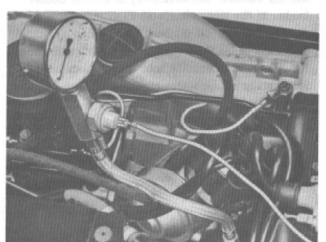
At page 188 one can also see the connector, this time empty, guess it was fitted to all cars but will often "disappear" at the 1st teardown.
/Lars S
QUOTE(larss @ Feb 11 2013, 10:10 PM)
QUOTE(914Eric @ Feb 7 2013, 11:12 PM)
QUOTE(Kirmizi @ Feb 7 2013, 11:16 AM)
That metal looks pretty dull as though it hasn't been used for awhile.
I don't recall ever seeing a spade connector there.
Mike
Yea...it is dull and nothing was connected. I just want to make sure that it was never connected...and not something a sloppy mechanic just forgot to connect. although there isn't any wires just hanging anywhere or even cut off. Not sure why the factory would add this ground to the cheesehead screw if it wasn't going to be hooked up to anything?
Hopefully, one of our resident engine gurus can answer this.
The factory manual (page 93)shows that tis connector was used to ground the oil pressure test gauge. I use it for the same purpose myself (grounding the test instrument).
At page 188 one can also see the connector, this time empty, guess it was fitted to all cars but will often "disappear" at the 1st teardown.
/Lars S
Another mystery solved! Lars...You ARE the man.

I was trying to figure out how to clean the trans of 40 years of baked on oil coating. It was like cement and I envisioned a week of scraping.
I had my torch out to loosen some cheesehead screws and thougt I'd see if would help clean off the tranny mess. 2 seconds with the torch and it scraped off like butter.
I had my torch out to loosen some cheesehead screws and thougt I'd see if would help clean off the tranny mess. 2 seconds with the torch and it scraped off like butter.
Been awhile, and I need a new fix...
how bout pic's of the clean tranny??
how bout pic's of the clean tranny??
Hello All,
Been down a while taking care of life. Should be back at it full time, hoping to be ready for the Dalles Oregon event soon.
So...first, after scrubing the trailing arms in preparation to pulling and painting them, I found more great news. The paint looks fantastic and the original assembly line markings are still in tact. The picture actually doesn't do the trailing arm justice...Looks far better in person. So I won't be pulling the trailing arms.
Second, trying to pull and replace the fuel lines through the tunnel, and need some advice. Looks to me that to do it, I'm going to need to pull out my console? The console is the only thing other than the dash left in the cab and I didn't see a need to pull it. Can the fuel lines be replaced without pulling the console?
Click to view attachment
Fuel line nipples in front of console under the fuel tank.
Click to view attachment
Pull the console. It's about 10 minutes worth of work, maybe 15. It's a whole lot easier to do that than to try to work around it for all the crap in the tunnel.
--DD
--DD
Hey glad to see you back at it, I was getting worried....
![popcorn[1].gif](http://www.914world.com/bbs2/style_emoticons/default/popcorn[1].gif)
quote name='turk22' date='Mar 22 2013, 06:08 PM' post='1838789']
Hey glad to see you back at it, I was getting worried....
[/quote]
Hey Steve...Thanks for keeping an eye out.
Pulled out the console so I can get the fuel lines out and all I found was another tiny access panel. Not much help, but maybe a little. Got a friend coming over tomorrow to pull from the engine compartment side while I watch the tunnel and try to push it through the front firewall.
Got a little surprise when I pulled the console out and lifted up the carpet: a big wedge of foam glued to the floor pan to give shape to the passenger side floor. See second picture.
Click to view attachment
Click to view attachment[
Eric - I just replaced my lines last week. A little lube on the rubber grommets and the ss line will slip right in. I gave my son a flashlight so he could guide the line through the tunnel and into the front bulkhead while I pushed from the engine compartment. It took 5 minutes from start to finish and on a scale from 1-10, was no more than a 2. It does help to have a helper and the engine out of the car.
Thanks Bum...Got the old lines out and will be replacing.
Once I pulled out the console, of course things were dirty, so I needed to remove the carpet for cleaning which forced me to remove the steering linkage, and then the pedal board. Deeper and deeper we go.
While it was a little dirty under there from mice droppings and 40 years of crud, the pedal board was amazingly pristine. Could use a light coat of touchup paint, but really doesn't even need that.
Click to view attachment
Click to view attachment
Really is amazing what condition some of these cars are in under all that crud. Keep up the good work, momentum is your ally! 
RPM,
Yea I have been really lucky in that other than the battery tray...This car has no rust. Helps that it spent its life in Cali, and half of that in storage in the high desert.
So here is a pic of the driver's floorboard and the pedal assembly. All 3 parts of the pedal assembly work smothly, and even the original paint looks nice...thus no need to rebuild. The paint under the driver's feet has some ground in crud that cleaned up nicely but still left the paint stained. It's under the carpet, so not really a big deal I guess.
Anybody think I need to do anything here before putting the pedal board, carpet, and console back in?
Click to view attachment
Personaly I would take the pedal cluster out, clean it, put in a brass bushing set, clean the floor and then button it up!
If the bushings haven't been done yet they will need to be at some point so why not now!
If the bushings haven't been done yet they will need to be at some point so why not now!
 Doing the bronze bushings is one of those "little things" that makes a huge difference. Much smoother operation.
QUOTE(Chris H. @ Mar 27 2013, 04:12 PM)
Doing the bronze bushings is one of those "little things" that makes a huge difference. Much smoother operation.Dammit you guys...Deeper and deeper and deeper I go. lol
I'm going crazy to start putting it back together and drive the thing. Spring is almost here.
I know Chris Shea does a complete rebuild, but everything seems to work really nice? But if they wear out and I'm already there...why not right?
Is it a fairly easy job of just popping in a couple of bushings or ???
Are the bushings available from the usual suspects; AA, Pelican?
Its the "while your in there" syndrome.
I'm able to drive mine, and that's why I'm reluctant to tear it all apart, cause while I'm in there, it may take a year before it get put back together.
I'm able to drive mine, and that's why I'm reluctant to tear it all apart, cause while I'm in there, it may take a year before it get put back together.
Been wanting to find my engine number for a while. Looked a few times and could never find it. Finally scrubbed away some gunk, and found it.
Engine number GA 000934
That along with my 001147 chassis number
and the vinyl on the window posts definitely shows an early 1973.
There is a great DIY article on Pelican on rebuilding the pedal cluster. It's not very hard technically but the roll pin can be a PITA to remove and/or reinstall (never reuse the roll pin, always replace it with a new one).
Check it here:
PP Article
Eric Shea re-does them very nicely if you don't want to mess with it. Better than new.
Check it here:
PP Article
Eric Shea re-does them very nicely if you don't want to mess with it. Better than new.
Chris H...Thank you for the pedal cluster article. Haven't read it yet, but I will.
So I ordered the "Super Pak" from RacerChris at Tangerine and have 5 SS fuel lines, fuel hose, injector elbows, fuel rail hose, etc... all coming in the next few days.
In preparation I'm checking out my injectors and noticed some odd things. While they are all green:
2 have press fit conectors.
2 had hose clamp connectors.
3 have black tips
1 has a green tip.
The ends on 3 open, and one appears stuck shut although I didn't force it.
I'm sending them all to WitchHunter to get them checked out, but I just wondered if anybody had any thoughts or insights as to why I have such a hodge-podge?
Click to view attachment
The hoses were originally on all of them, but if you cut them off carefully you end up with what is on the right. It should work equally well either way. I ordered and installed 4 new from Otto's in CA when I did my engine refresh last year so I would have some spares (but mine were leaking a bit already). ~90$ ea. I think.
QUOTE(rnellums @ Mar 29 2013, 06:30 AM)
The hoses were originally on all of them, but if you cut them off carefully you end up with what is on the right. It should work equally well either way. I ordered and installed 4 new from Otto's in CA when I did my engine refresh last year so I would have some spares (but mine were leaking a bit already). ~90$ ea. I think.
Auto Atlanta's website lists new OEM porsche injectors for $321. Ouch. They also list new Bosch for $255. I wonder if those are the same without the "Porsche" box?
They also have rebuilt listed for $75. Pelican doesn't have anything at all.
You say you got new from Otto's for $90...New What? OEM, Bosch, or ??
New OEM Bosch, although I'm not sure how many are left.
http://www.914world.com/bbs2/index.php?sho...40025&st=90
post 97 are photos
http://www.914world.com/bbs2/index.php?sho...40025&st=90
post 97 are photos
QUOTE(rnellums @ Mar 29 2013, 11:02 AM)
New OEM Bosch, although I'm not sure how many are left.
http://www.914world.com/bbs2/index.php?sho...40025&st=90
post 97 are photos
Ross,
Thanks for the link to the injector pics. While I was in there I got to really look over your car. Hadn't seen your thread before. VERY nice. I really like the unusual color.
Seems like if you got those Bosch injectors for $90...I'll need to give Otto's a call. Far cheaper than AA.
Are they still going? Otto passed away not long ago...
--DD
--DD
Was looking back to try and find a particular post and realized that since the thread has gotten so big that I needed an index.
It is now in the page header to help find particular topics.
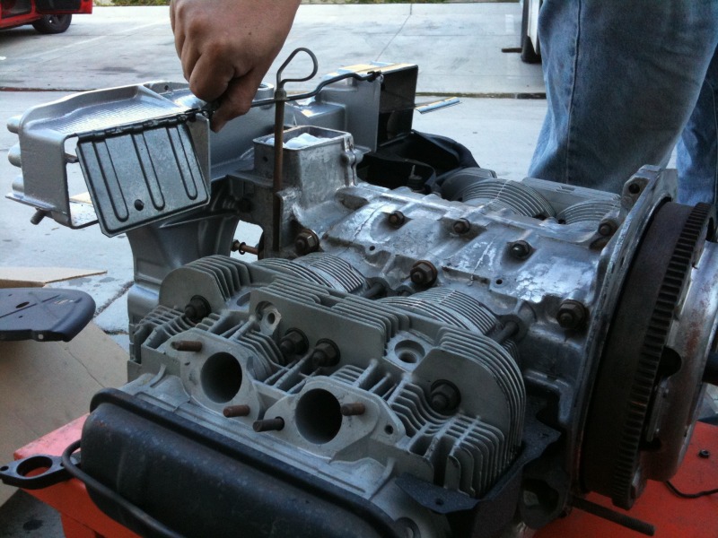
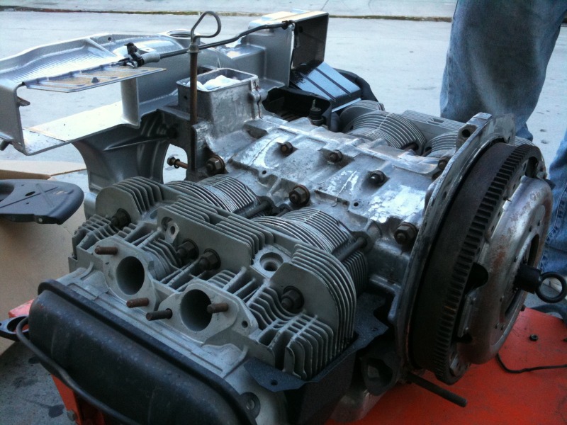
Trying to pull the front blower housing off the engine and got all the cheeshead and hex bolts out but it still won't come off. It's loose all the way around the perimeter, but seems to be held by the large pulley or an "odd" fastener underneath the small pulley. The fastener is like a round carriage bolt with two flat sides.
Factory manual says to remove the 3 bolts on the large pulley, but when I try...It just spins the engine. How do you keep the engine from spinning to remove the pulley bolts?
How to remove the round headed bolt with the two flat sides? See arrow. It's always easy once you learn the technique.
Thanks Guys.
Click to view attachment
The round headed bolt has a square shoulder like a carriage bolt that fits into the alternator bracket, so all you need to do it loosen the nut on the other side. For the fan hub I usually use a flywheel lock that bolts to the case and has teeth that lock the flywheel, I picked mine up at a VW shop a while ago. Between the two case halves there are also two alignment pins. those usually are what holds it together after removing all the screws for me. a bit of rocking usually does a trick. A screwdriver might work too, but it will easily mar the metal.
Hey Eric, glad to see you working on it again.
The bolt by the arrow is the pivot point for your alternator. On the back side of the alternator, there is a nut that must be removed to pull that bolt out.
You do not need to separate the two halves of the fan housing, unless you feel the need to clean where no one will ever see. You will need to pull the fan off to get to the four bolts holding the fan housing to the engine case.
If you use any type of water-based cleaner on the fan housing, dry it immediately. It will pit it permanently if left to soak (ask me how I know).
You can't safely remove the fan without a flywheel lock, or some other means of holding the rotating assembly in a fixed position. Whatever you do, don't try wedging something between the fan blades. They will snap off. I strongly recommend the flywheel lock. Pelican has them.
Are you replacing the front main seal? If so, you will also need to pull the fan hub from the end of the crank. This requires a special tool that you can easily make if you have a welder. Basically a flat steel "C" shape. I can mail you the one I made if you don't weld.
Grab yourself an impact gun (air or electric) for fasteners just like the fan bolts. Makes life so much easier.
Mark...or anyone,
Will an impact gun get the fan bolts out without a flywheel lock?
Hi Ken...
Will an impact gun get the fan bolts out without a flywheel lock?
Hi Ken...
Yes, that's one of the things impact guns are for. Loosening things that you can't hold still.
BTW, I have been lucky enough not to break any fan blades by putting a long screwdriver through the timing hole and the fan. I try to keep the screwdriver at the back of the blade where it attaches to the rest of the fan; the blades are a little bit stronger that way. (Still some risk of breaking them, though.)
--DD
This is a "lo-fi" version of our main content. To view the full version with more information, formatting and images, please click here.