Help - Search - Members - Calendar
Full Version: Out with the old...in with the new...Britain's Racecar Development
914World.com > The 914 Forums > 914World Garage
Pages: 1, 2, 3, 4, 5, 6, 7, 8, 9, 10, 11
Britain Smith
Progress has been a bit slow the last couple of days, but it is starting to pick back up.

Finished up the front truck area. I replaced the foam in the fuel tank and completed all the fuel lines.

IPB Image

Got the AIM MXL dash mounted and ordered the Subaru interface harness so that I can read everything off the ECU.

IPB Image

I also started plumbing all the brake lines and drew up the wiring diagram.

-Britain
Hontec
Read the whole topic ......again...... Simply amazing work Britain..

Love the Tilton pedal box.......I will be installing a similar one......
Keep up the great work, you're certainly doing a lot in a short period of time.... piratenanner.gif
Britain Smith
Thanks Hontec...your work is far superior, I am just trying to get my car together before the race season starts.

I got the welder back from my buddy who I am borrow it from so I was able to make good progress tonight. First I finished up clean the firewall. There were several large holes that were used to secure the 914/6 engine mount that have now been welded up.

IPB Image

View from the backside of the firewall with the holes welded up and the brake line rerouted to avoid hitting the turbo.

IPB Image

Turbosmart Dual Stage Boost Controller taken off my '69 912 Turbo project. This will work well for those tighter courses or wet weather occasions.

IPB Image

Pedal assembly plate welded in. These welds are not as pretty as I would have liked, however trying to weld in the cramped footwell was not easy and I had to ensure I didn't burn thru the floorpan.

IPB Image

Tilton pedal assembly mounted. The positioning is perfect and the mount is very sturdy.

IPB Image

Intercooler ice box mounted. This will fit just in front of the passenger seat when I take passengers.

IPB Image

Ice box plumbing. There is a ball-valve to drain the water under the car.

IPB Image

Ice box plumbing view down to the water pump. Had to route the lower water hose thru the crossbar so I welded in a tube to keep the strenght.

IPB Image

Off to bed, more to do tomorrow.

-Britain
plymouth37
Beautiful as usual, this is going to be one hell of a ride!
Britain Smith
Ha, you are up just as late as I am...best time to get things done.

-Britain
Hontec
Lookin' good!!! really love the pedalbox! and the dash is first.gif
Britain Smith
Took the son karting yesterday. It was his first time at a dirt flat track and although he started off slow, he really got the hang of it and it was a lot of fun.

IPB Image

Anyway, back to work. Got the business end almost completed. Just had to put the seat back in to feel the new pedal/shifter/dash set-up. I will admit, I did sit there and make car noises for a bit. The last thing that needs to get done here is a panel for the ignition switches.

IPB Image

Reinstalled the engine to take some measurements for the throttle cable and clutch hose. Got the air intake installed and a bracket made to mount it.

IPB Image

Fuel lines installed. Startlite line may cost a little bit more, but it is SO much nicer to work with and lighter.

IPB Image

Got the intercooler back from being welded up by Marty Staggs (www.m-specmotorsports.com), turned out perfect.

IPB Image

Starting to fab up a heavy duty mount off the engine block. The intercooler is fairly heavy as it sits and will be twice as heavy when the water is added.

IPB Image

Hopefully I can wrap up all the fab items over the next week or so and then focus on the wiring. Although I am still waiting on my custom flywheel, I am still on track to have this thing fired up by the beginning of Feb.

-Britain
Britain Smith
Was able to take the intercooler mount to the machine shop today and get welded up so that I could finish the routing of the intake piping. I also had some aluminum standoffs machined up to mount the bracket to the top of the engine block where the original alternator and power steering brackets were secured. I will take the rest of this to get welded up later this week.

IPB Image

IPB Image

Intake piping between the turbo and intercooler mocked up.

IPB Image

IPB Image

Even though I rotated the compressor side of the turbo I was still able to use a Grimmspeed bracket (with a little modification) to lock the internal wastegate closed.

IPB Image

Found a nice solution for the oil feed to the turbo from Forced Performance. Consists of a custom made banjo bolt machined with an AN-4 male fitting on the end. The stock hard line that used to feed the turbo has a machined fitting to cap the oddball size threads. I will run a short lenght of AN-4 hose over to the turbo.

IPB Image

While I was having other aluminum stuff welded today, I took the time to add some reinforcements plates to the shifter housing after I found that it was flexing just a little bit where the cable mounts.

IPB Image

-Britain
URY914
I like it. beerchug.gif
sean_v8_914
bravo zulu!
sawtooth
Fantastic! Nearing the end of my suby conversion, I am baffled by the mount of knowledge and confidence it would take make something like this come together, especially how fast you are getting it done. I'm jealous of your knowledge of turbos, what to use and why, and how to make it all come together. Keep up the great work, hope to see your car run ax at WCR!
Britain Smith
I learned a lot when I did my 912 Turbo project. I have also done a lot of research and planning...that and I like to do things a little different.

-Britain
Elliot Cannon
Will we see this monster at the WCR?
Britain Smith
That is the plan...

-Britain
Walter
Very nice work indeed!
If you're aiming at ~400 hp, I would have chosen a 3" downpipe however, especially since you've also routed the wastegates in the 2,5" piping.
Well, you can always 'upgrade' later if you would want to ;-)
Britain Smith
The wastegate piping goes from 1.5" to 1.75" then into the exhaust which is 2.5"

-Britain
Walter
QUOTE(Britain Smith @ Jan 19 2011, 01:49 PM) *

The wastegate piping goes from 1.5" to 1.75" then into the exhaust which is 2.5"

-Britain

I know, I had read that biggrin.gif
Its just a little better then internal wastegate(s) what you did as the whole idea to external besides the control side is to not 'mess up' the exhaust flow giving it extra back pressure, even if its a few psi.
Turbo's are very sensite to back pressure and 2.5"is on the small-ish side for 400 hp. Better is to route ext. gates into their own downpipes and their own silencers.

Another thing to consider if you get dB problems with some tracks is the ext.gates actually need even better silencers as they don't have the turbo to pre-silence them... I also found this out the hard way at soem track when my wastegate opened and I got past the post that measured sound...

Just thinking along with you Britain ;-)
Britain Smith
Understood Walter.

Since the engine is only a 2.0L and I am running the stock turbo (for faster spool time) I don't plan on getting 400hp...more like 350hp max. The path towards external wastegates was for better control of boost pressure as the internal gate has issues when running over 20lbs of boost as I plan to run. It also helps that I am partially sponsored by Turbosmart and have their wastegates, BOV, and fuel pressure regulator on my car.

Regarding the exhaust routing, the need to combine them into the exhaust stream was necessary due to not only sounds requirements but also restricted space. By dumping into the exhaust stream, I am able to control the sound levels thru muffler arrangements. Now, you are correct it would have been better to dump into their own silencers, however space is limited and that also weighs more smile.gif

-Britain
plymouth37
Wow! Looks amazing!
Elliot Cannon
QUOTE(Britain Smith @ Jan 19 2011, 11:58 AM) *

That is the plan...

-Britain


Will we all get to drive it? driving.gif driving-girl.gif lol-2.gif
Britain Smith
You all get to watch me drive it, that should be satisfaction enough right? smile.gif

-Britain
maf914
Britain, Beatiful work! Thanks for posting this thread.

Okay, I suspect this will be a dumb question. Regarding your shifter arrangement, I can see the fore and aft motion, but how does that single cable provide a twisting or side to side motion? A two speed, one-two shift? Or is it a sequential shift? idea.gif
Rand
QUOTE(maf914 @ Jan 20 2011, 07:01 AM) *

Okay, I suspect this will be a dumb question. Regarding your shifter arrangement, I can see the fore and aft motion, but how does that single cable provide a twisting or side to side motion? A two speed, one-two shift? Or is it a sequential shift? idea.gif

See post #84
maf914
QUOTE(Rand @ Jan 20 2011, 10:01 AM) *

QUOTE(maf914 @ Jan 20 2011, 07:01 AM) *

Okay, I suspect this will be a dumb question. Regarding your shifter arrangement, I can see the fore and aft motion, but how does that single cable provide a twisting or side to side motion? A two speed, one-two shift? Or is it a sequential shift? idea.gif

See post #84


I quess I was right. It was a dumb question. laugh.gif

Thanks for clearing that up, Rand. smile.gif
Britain Smith
Yep...special 2-speed transmission.

Thanks for the good words.

-Britain
Chris Pincetich
Awesome.
I had a big heavy battery break its mount in an AX race, so totally appreciate the extra thought and work you did to mount the intercooler. Water is so heavy, maybe why Porsche stayed away from it so long.... biggrin.gif

One day I hope to steal one of your ideas = the cooler mounted in front of the passenger seat. Genius! Although mine would have room for beverages beer3.gif
beerchug.gif
Britain Smith
I was on a roll last night and up pretty late, but made some good progress.

Intercooler mounting completed. Everything fit pretty well considering I had to mock it up at home and take it to a shop to get welded.

IPB Image

Turbosmart BOV mounted on the underside of the intercooler just before the throttle body.

IPB Image

New gauge panel completed and mounted. I had this piece waterjet so that all the holes with line up properly and saved me a bit of time.

IPB Image

Front fuse box and relays for fuel pump, radiator fan, and intercooler water pump.

IPB Image

ECU mounted in the trunk. Not looking forward to sorting out the wiring.

IPB Image

I should be able to get the engine back in there this evening and start finalizing all the plumbing.

-Britain
bam914
Are the floor mount pedals installed any further forward then the stock setup? Thinking about them for my car.
BMXerror
All your stuff looks so damn good... Professional, even. Must be the yellow background it all goes in front of. poke.gif
Makes me jealous. first.gif Keep up the good work. Can't wait to see what it does in XP.
Mark D.
Britain Smith
QUOTE(bam914 @ Jan 23 2011, 06:51 PM) *

Are the floor mount pedals installed any further forward then the stock setup? Thinking about them for my car.


With the very short master cylinders from Howe Racing they are set identical to the stock set-up. Sitting in the seat they feel perfect. Under that steel plate I made some ribs to ensure I have no flexing of the mount.


-Britain
Britain Smith
QUOTE(BMXerror @ Jan 23 2011, 07:52 PM) *

All your stuff looks so damn good... Professional, even. Must be the yellow background it all goes in front of. poke.gif
Makes me jealous. first.gif Keep up the good work. Can't wait to see what it does in XP.
Mark D.


Many Many Hours my friend. I have almost 3 straight months on this and I don't want to even mention the budget other than to say that I am "slightly" over smile.gif

-Britain
Britain Smith
Got up late this morning after the late night last night...but once I got going I got some good stuff done.

Third iteration of the brake line routing. The 2nd iteration interfered with the brake line routing. This time the brake lines are routed inside the cabin and then thru the firewall over the framerails.

IPB Image

IPB Image

Engine bay with the intercooler installed. Getting pretty busy in there.

IPB Image

IPB Image

Intercooler water lines routed thru the firewall to the pump/tank.

IPB Image

-Britain


bam914
I found these last night. You build a box over the master cylinders for your feet. I am 6'4" this would be nice to get the pedals further forward.

Click to view attachment
Britain Smith
Wow, those look cool. Where did you find them? Little late for my car, but nice to keep as a reference.

-Britain
JFJ914
QUOTE(bam914 @ Jan 24 2011, 06:58 AM) *

I found these last night. You build a box over the master cylinders for your feet. I am 6'4" this would be nice to get the pedals further forward.

Click to view attachment

Blake,

Turn them over and hang them from the top bulkhead.
BKLA
This thread sucks! And your mother dresses you funny!

See you Saturday with s'more karting stuff! biggrin.gif
bam914
QUOTE(John Jentz @ Jan 24 2011, 03:19 PM) *

QUOTE(bam914 @ Jan 24 2011, 06:58 AM) *

I found these last night. You build a box over the master cylinders for your feet. I am 6'4" this would be nice to get the pedals further forward.

Click to view attachment

Blake,

Turn them over and hang them from the top bulkhead.


These require no cutting or major bracket making. I don't like hanging pedals.

Here is the company that has them. http://obpltd.com/
BMXerror
QUOTE(Britain Smith @ Jan 23 2011, 09:54 PM) *


Many Many Hours my friend. I have almost 3 straight months on this and I don't want to even mention the budget other than to say that I am "slightly" over smile.gif

-Britain


I hear that. I've had some days lately where I work a ten hour shift at the machine shop, and then stay an extra 8 hrs making some part for the SDS install. Hard work: You never get anywhere without it. Keep on keepin' on Britt.
Mark D.
Britain Smith
Summary of the work completed over the last couple of days.

Went to install the starter and finish up the wiring and found that the position of the engine caused the starter to hit the trunk floor. Therefore I had to make this raised panel for clearance.

IPB Image

View from underneath. I made the panel with the transmission in the car. When I pull the trans to install the new flywheel I will clean this area up.

IPB Image

Throttle cable bracket completed and all adjusted. The feel of the throttle pedal is perfect.

(I got the throttle cable made custom from Terrycable and due to an error on my part, the first one I ordered was a bit short. If anyone is building a Suby conversion and needs a throttle cable 90" long let me know. It would work perfectly on a car with the intake manifold in the stock orientation (i.e. pointing back).

IPB Image

Throttle cable mounted in the engine compartment.

IPB Image

ECU mounting and the majority of the wiring completed. Still need to finish the alternator wiring and some various sensor for the VSS (Vesicle Speed Sensor) and NPS (Neutral Position Switch).

IPB Image

Switch panel has power. Lets see, we got master on, fuel pump, radiator fan, intercooler water pump, and boost switch.

IPB Image

Dash display wired in and working. Not sure where it is getting the Oil/Water/EGT numbers as the ECU was not on...maybe memory from the engine it was installed on previously.

IPB Image

Right now the ETA on the custom flywheel is end of next week. If that happens then I should make it to the dyno the week of Feb 14th...almost there smile.gif

-Britain
Rod
Superb - Really gaining pace now. If it were me I'd want to strip it all out and respray the shell inside and out - it just looks soo good smile.gif smile.gif
Britain Smith
QUOTE(Rod @ Feb 3 2011, 07:30 AM) *

Superb - Really gaining pace now. If it were me I'd want to strip it all out and respray the shell inside and out - it just looks soo good smile.gif smile.gif


Yea, that would be a great plan if I had 6 more months to build the car...however, the race season started in 4 weeks. I need as much time as I can get to finish the car and start sorting it out.

-Britain
Chris Pincetich
I am loving the blend of old and new in your 914 beerchug.gif
Inspirational work. Subby transplants are just so nice. I am sure it will be smokin fast with less fuel consumption
grantsfo
Looking good Brit! I knew you would eventually figure out how to make a fast prepared ax 914! I'm about to throw up my hands like JP did and dump the Boxster to someone who has time and money to do it right. Most people have no idea what it takes to build a national level ax car. If you think about it this 914 has been in serious development in modified and prepared form for over 7 years and I think it's just getting to the point of being nationally competitive in prepared this season but suspect you have lots of sorting left prior to nationals. I suspect you will be working on suspension balance as turbo power is sure to be different than NA car was setup. Again this is very exciting!

Looking forward to seeing it run with big dogs! Are you coming down to SD again?
Britain Smith
Hey Grant...haven't heard from you in a while.

I have a dyno date in 2 weeks so I am in the final push to get this thing running. I doubt I will make San Diego this year as it is a little too close to ensure I have the car sorted. We shall see what happens over the next few weeks.

-Britain
Britain Smith
Ok, I am on the final push towards the end. I have dyno time schedules for Friday, Feb 18th at Cobb Tuning Surgeline. Still waiting on the flywheel, but I can get everything else prepared in advance.

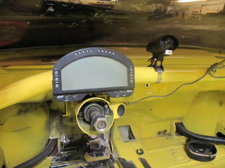
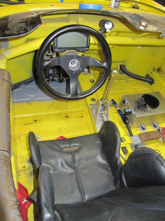
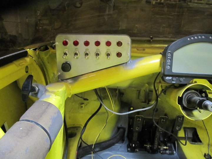
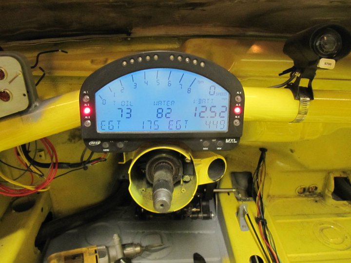
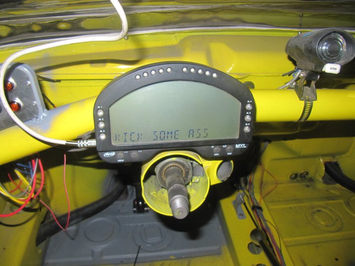
Reprogrammed the dash for a little pre-race inspiration. smile.gif 
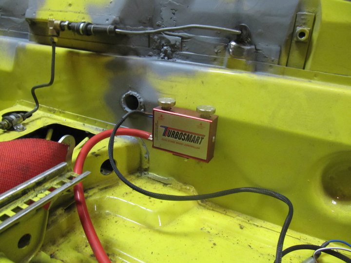
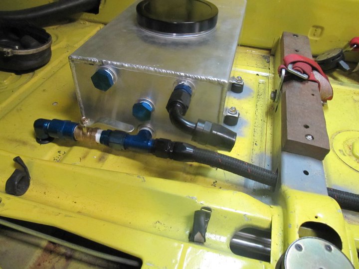
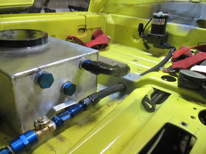
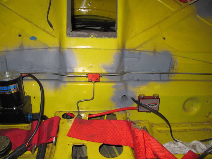
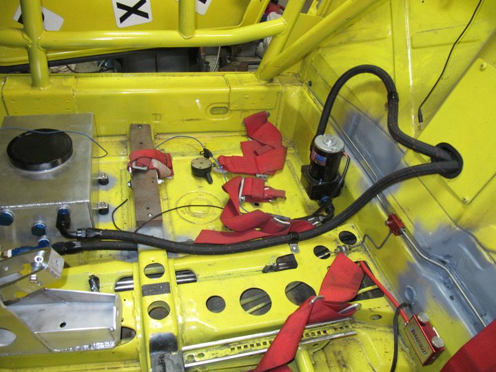
I also wired up the oil pressure, oil temp, fuel pressure, and water temp sensors to monitor on the dash.

IPB Image

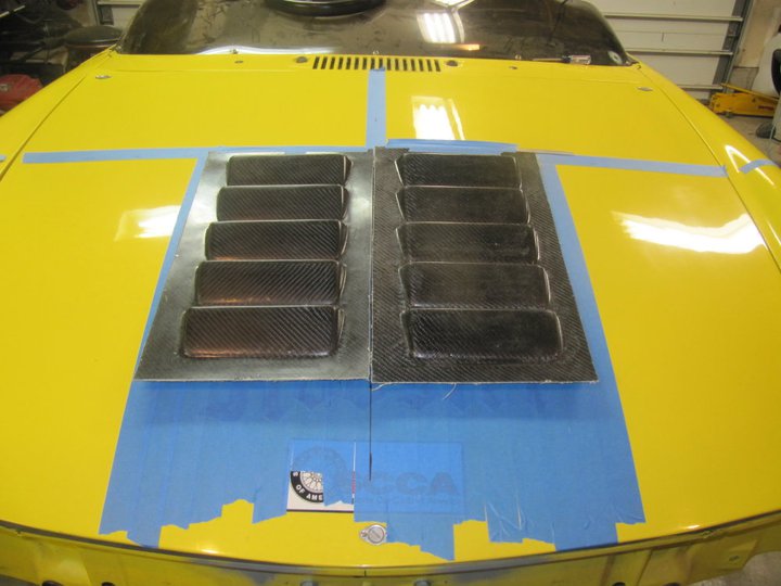
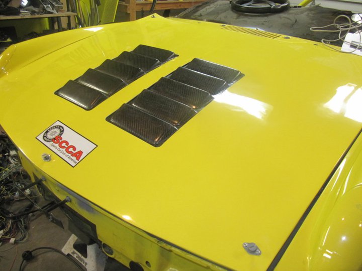
For radiator venting thru the hood, I purchased two louvered panels. These things were pricey and I was less than impressed with the quality. However, they will serve a purpose and I have to remind myself that this is just a race car.

Here are the panels in the approximate location on the hood.

IPB Image

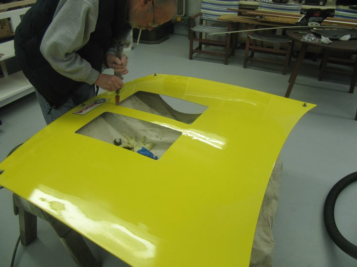
I took the hood up to JP's shop to make the cutouts. Fortunately I was able to get JP off his butt to help cut the hood. Notice that he can't do anything without a cig hangin out of his mouth. smoke.gif

IPB Image

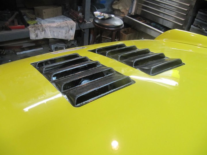
Here are the panels bonded to the back of the hood and in place on the car.

IPB Image

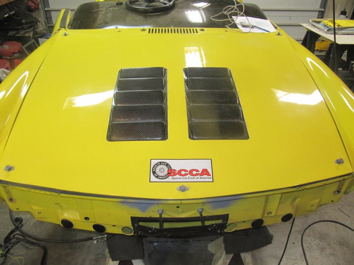
Side view, they are just under the 1" height restriction as per SCCA.

IPB Image

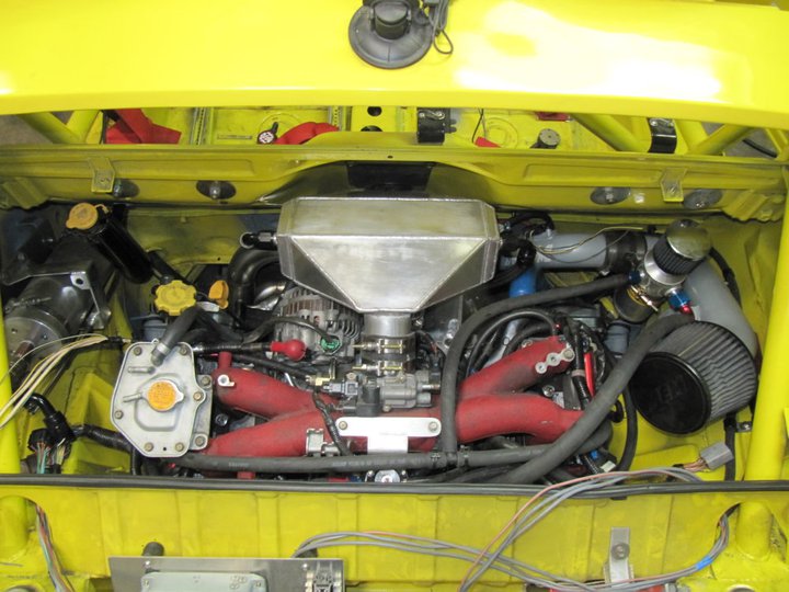
Looking down into the hood you can see the radiator and fan.

IPB Image

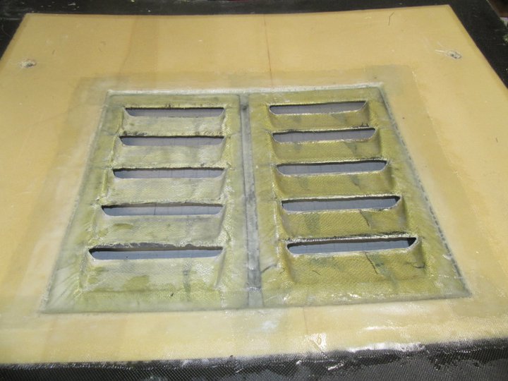
On the backside, you can see the area of the core mat we had to remove to bond directly to the backside of the hood. Added an additional layer of epoxy to the backside for strength.

IPB Image

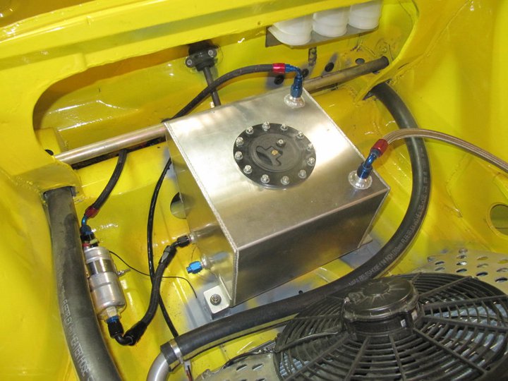
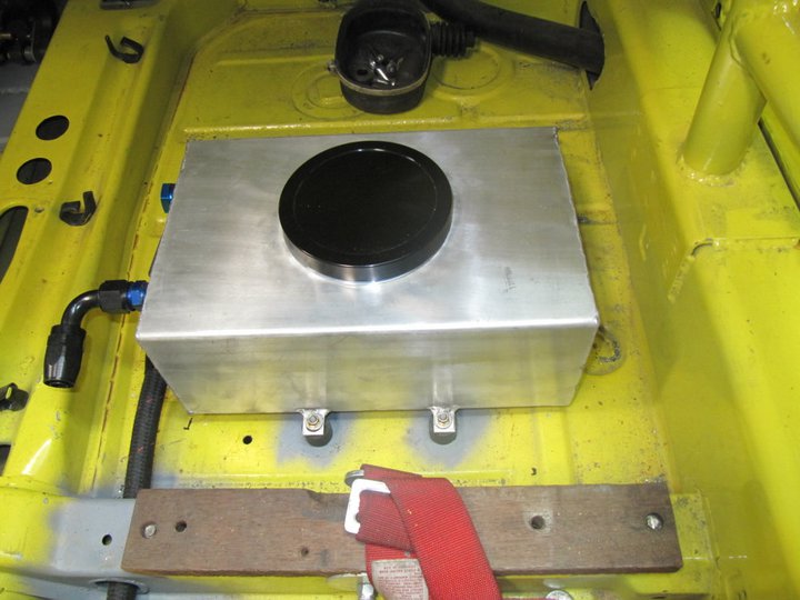
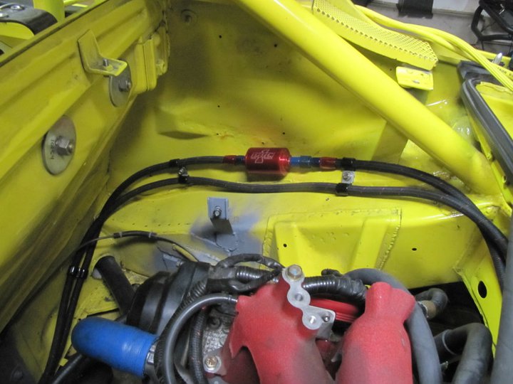
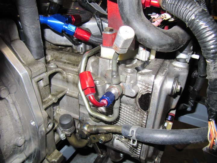
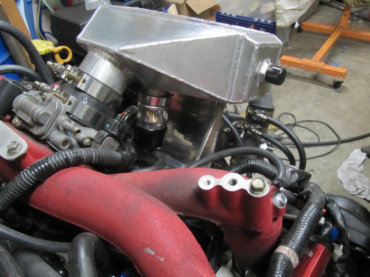
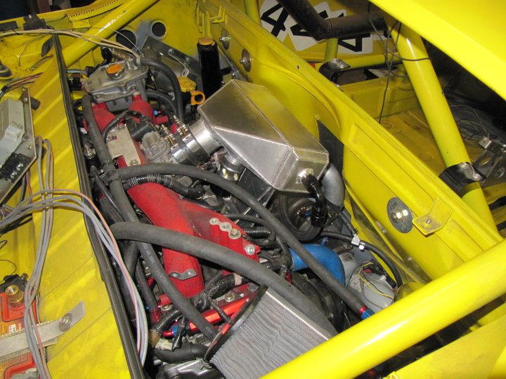
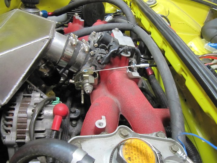
I also was able to put a gallon of fuel in and test the system...good idea that I did this now as I found a pinched injector o-ring and had to get a new set on order. It was fun to have 45psi of fuel squirting out of the fuel rail.

-Britain


DanT
Hood came out nice Brit, even with JP doing the cutting biggrin.gif

I have probably forgotten but where is the air coming in to the radiator from...?
Britain Smith
Air entering the oil cooler cutout location in the front bumper.

-Britain
sawtooth
Looking great Britain. Make sure, double sure to shoot some video of your car on the dyno for us, please?
Andyrew
Is the radiator going to be shrouded to the vents? Just curious.

Were those louvers flexible to mold to the curve of the hood? Curious how you managed that.


Looking good as usual!
Britain Smith
The recent change to the SCCA rules do not allow ducting from the radiator to the vent. I am still trying to clarify exactly what I can and can't do. As per the rules I also need to add a mesh screen under the louvers...again, trying to clarify.

As for the curve of the hood, the louvers were fairly flexible but I had to use a bunch of weights and some strong epoxy to get the shape right...took all weekend to set.

-Britain
This is a "lo-fi" version of our main content. To view the full version with more information, formatting and images, please click here.
Invision Power Board © 2001-2024 Invision Power Services, Inc.