QUOTE(charliew @ Dec 13 2010, 09:13 AM)

When I studied the smartcar vss a few years ago I bought one but my understanding it is only to make sure the car is in motion, it will not replace the speedo feedback.
Yea, that is my thought as well. However, using the Small Car Performance speedo sensor kit I should be able to get relative speed numbers and I can feed that into my AIM dash for datalogging.
QUOTE(charliew @ Dec 13 2010, 09:13 AM)
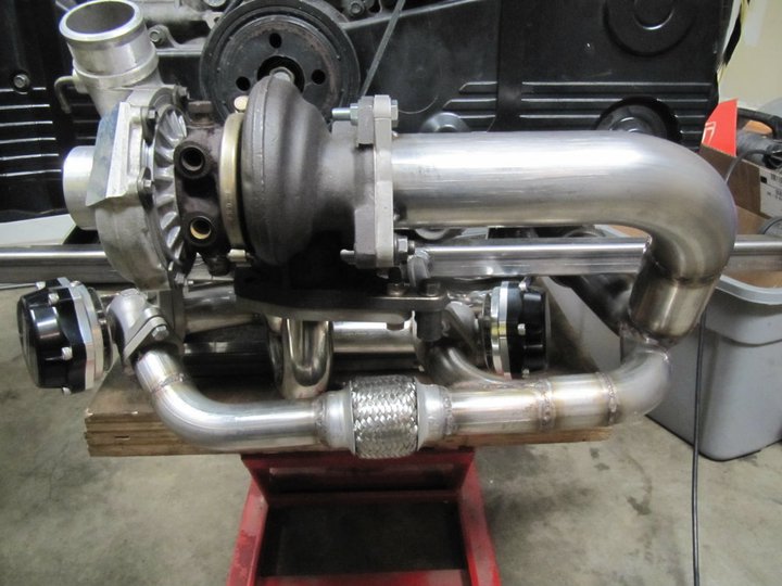
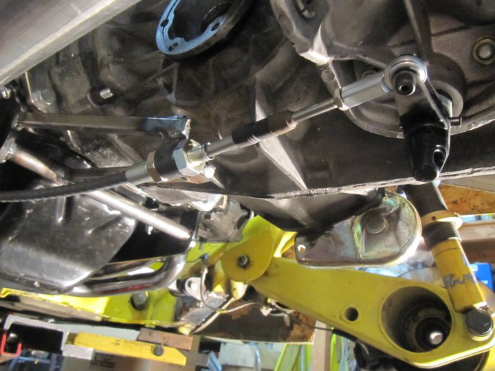
I guess you know what you are talking about on needing the two waste gates. My thought is the inlet side using two waste gates might reduce the surge of the turbo better but the pulses from each exhaust port would seem to me be better controlled after the turbo wheel rather than before to get the quickest spool time.
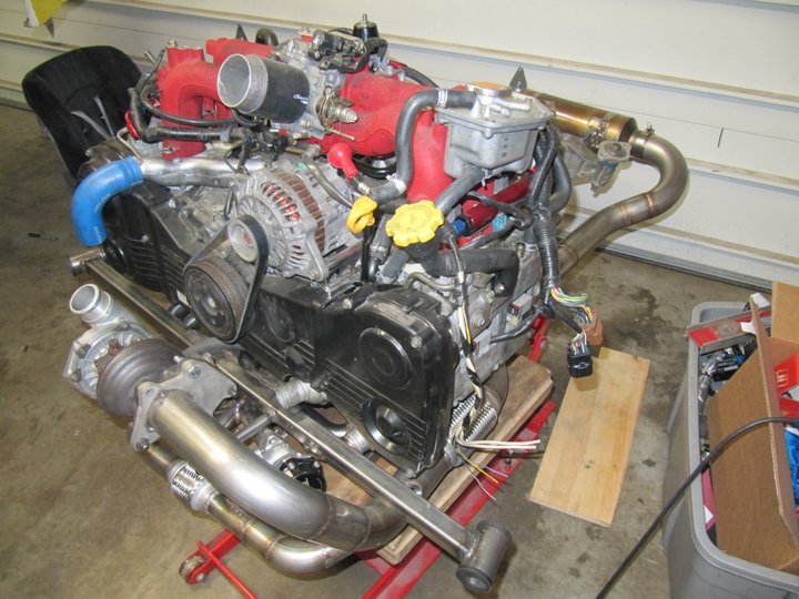
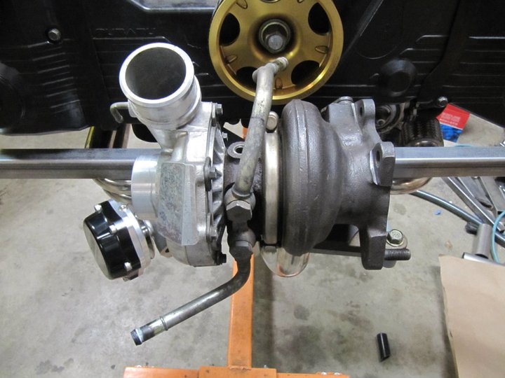
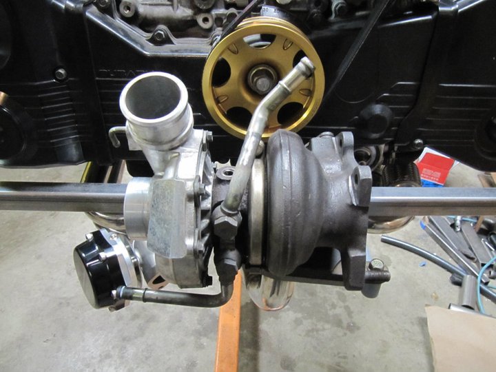
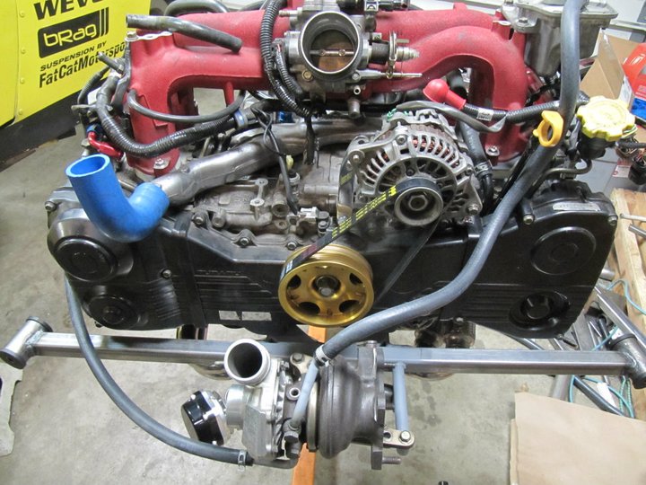
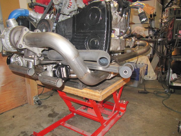
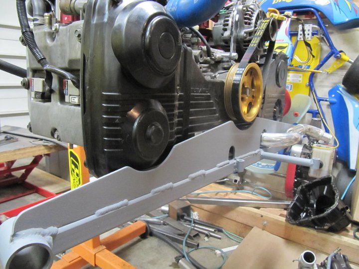
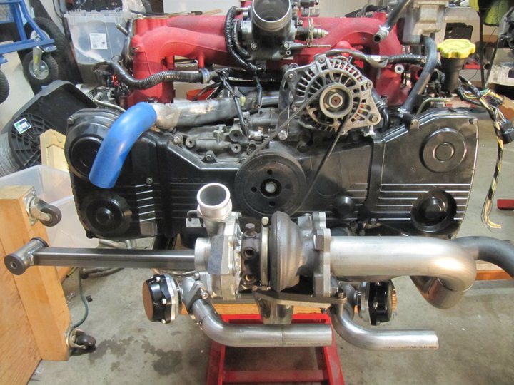
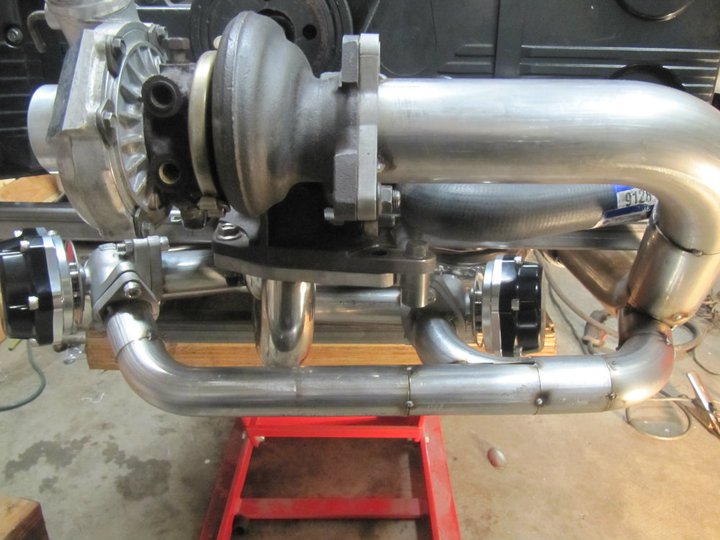
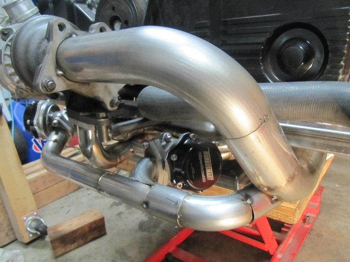
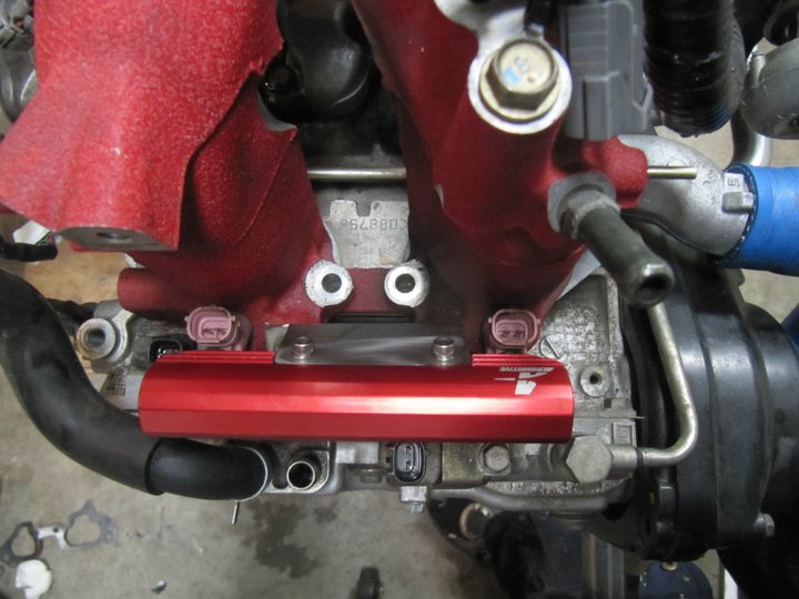
The wastegates go before the turbo and the blow-off valve goes after the turbo. I need two wastegates because I have cylinders 1 & 3 and 2 & 4 entering the turbo separately (twin-scroll) and the two wastegates will keep the exhaust pulses independent. Wastegates control the amount of exhaust gases that go to the turbo and therefore control the boost pressure. The blow-off value is between the turbo and the throttle body to reduce surge of the turbo when the throttle is closes...the pressurize air needs somewhere to go.
QUOTE(charliew @ Dec 13 2010, 09:13 AM)
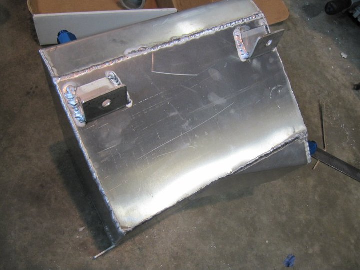
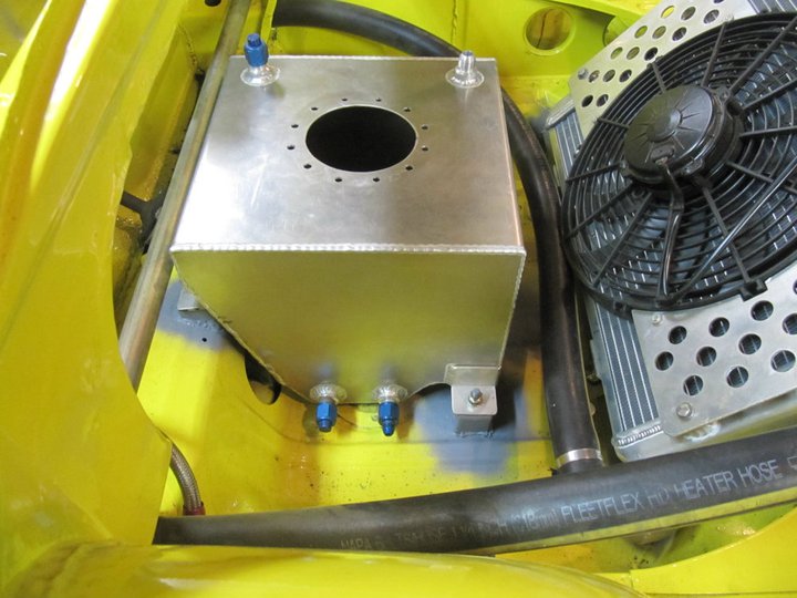
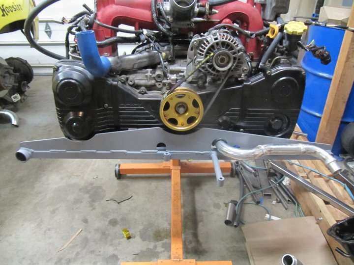
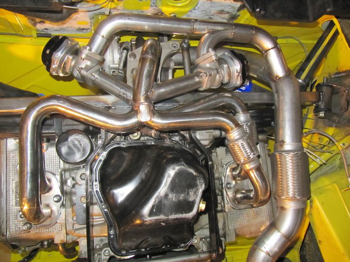
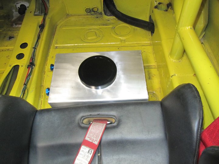
You are doing great though and will be a very valuable source on what works at high rpm in the 914 high g suby configuration. The suby uses more oil than you will think at high rpm and high oil temps so monitor it very carefully. Now that the twin scroll exhaust is removed I would tackle the oil pan and try to get as much more capacity as you can. The oil pickup is a very critical spec on the suby motor, there is a lot of variation in the oil pan tp pickup clearance. The external oil cooler is really necessary, get a oil temp sender and good gauge. The good thing is it's a race car and you can change over heated oil pretty regularly.
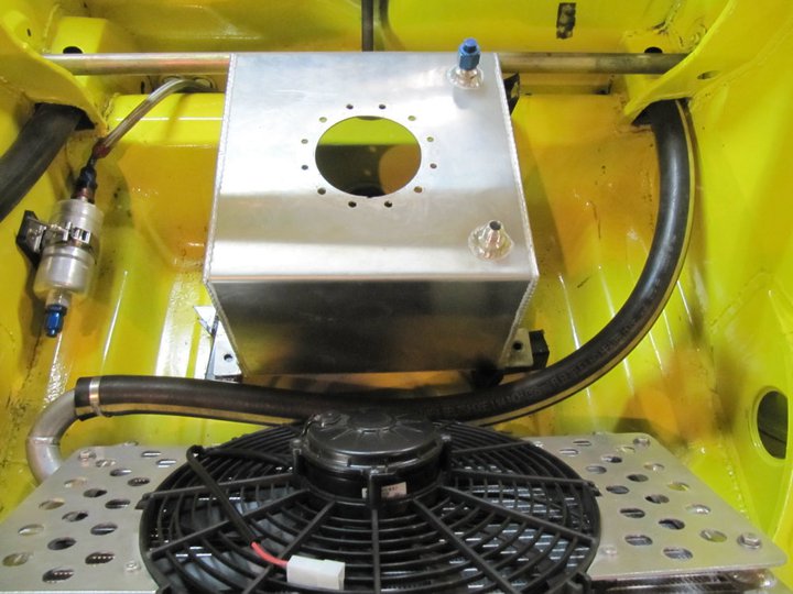
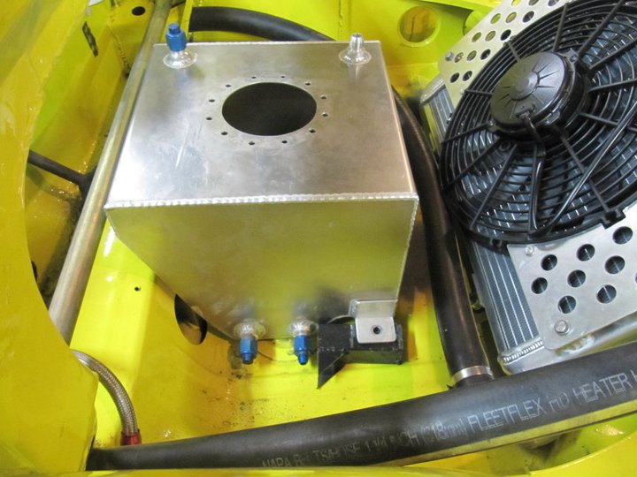
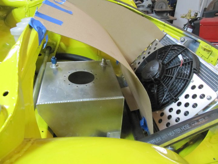
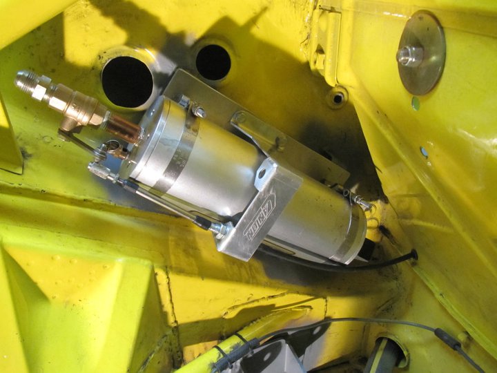
Yes, I am also concerned about oil pick-up under the conditions that I run. I have an Accusump plumbed in and will be address the oil pan after the engine is running on the dyno.
QUOTE(charliew @ Dec 13 2010, 09:13 AM)
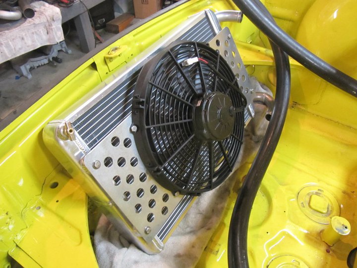
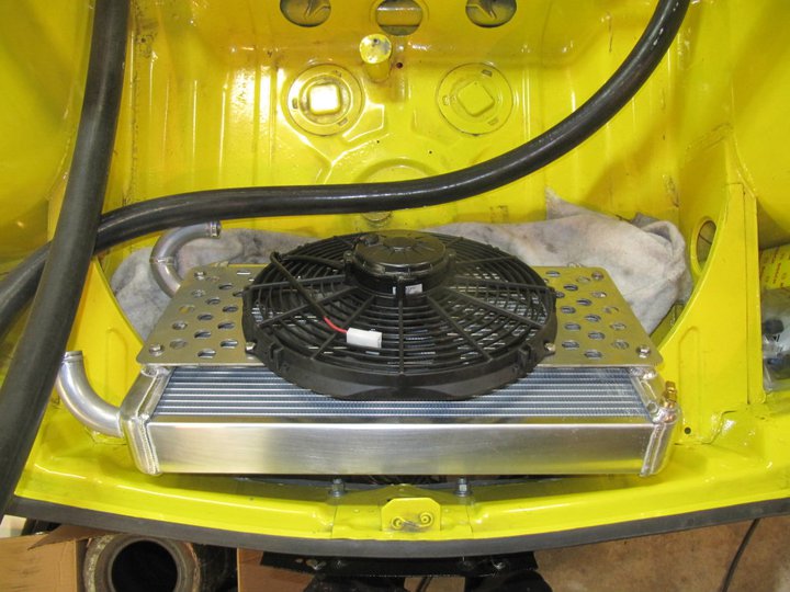
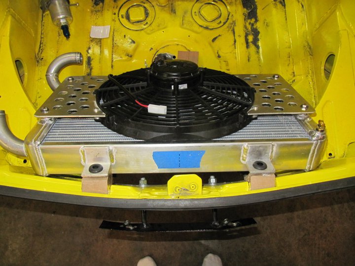
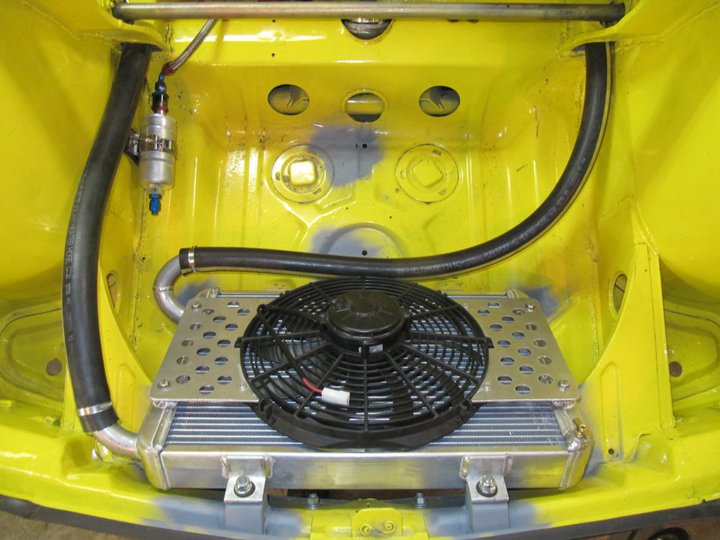
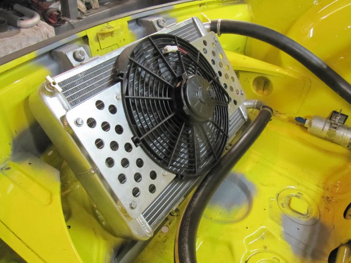
You also may have considered a turbo blanket I hope. Are you going to learn to do open source programming on the oem ecu also? I am anxious to see if your radiator is going to be big enough. If the boost is laggy you might want to check the exhaust back pressure at the turbo. The exhaust on my son's sti is at least 3.0 all the way with straight through muffler and no cat. Your exhaust is shorter though. I do wish you had gone with the suby tranny also.
Yes, I have considered a turbo blanket or heat shield...we shall see how things go on the dyno.
Yes, I am using Open Source tuning...however this will be done at Cobb Tuning.
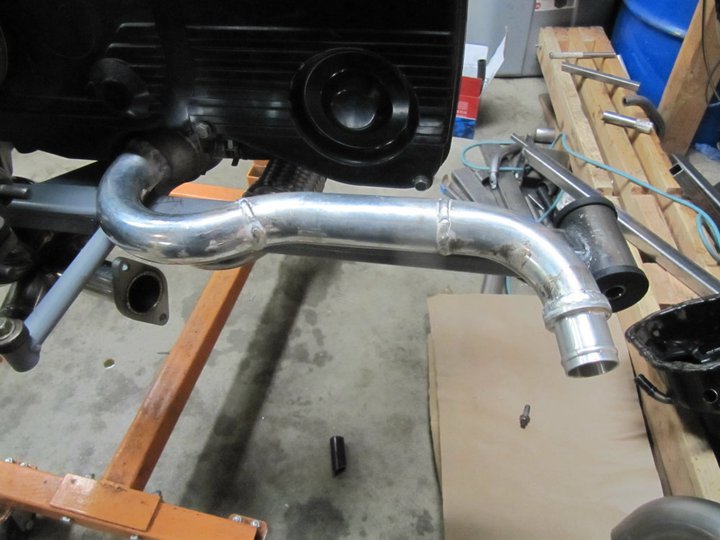
The exhaust is 2.5" all the way back and with the smaller turbo, it should be fine.
I might be changing to a different trans, we shall see how long the 901 lasts.
-Britain
 I'm amazed that you're doing so much, so quickly. And it looks like quality sh*t too! Where do you find that kind of time?
  Keep it up.


 . It being the shitbox it is probably reinforced up there so flex isn't an issue. This is as close to helping as I will probably get