Help - Search - Members - Calendar
Full Version: Project Time! 71 garage build
914World.com > The 914 Forums > 914World Garage
Pages: 1, 2, 3, 4, 5, 6
FourBlades

Nice work! smilie_pokal.gif

John
dfelz
Thanks for the update Ethan and the warm congrats from the rest! I am really happy to finally be at this point of the build, but there are a few more adjustments/additions that need to be made before its a real teener.

Tomorrow i have a tune-up on the schedule! smash.gif driving.gif smash.gif
dfelz
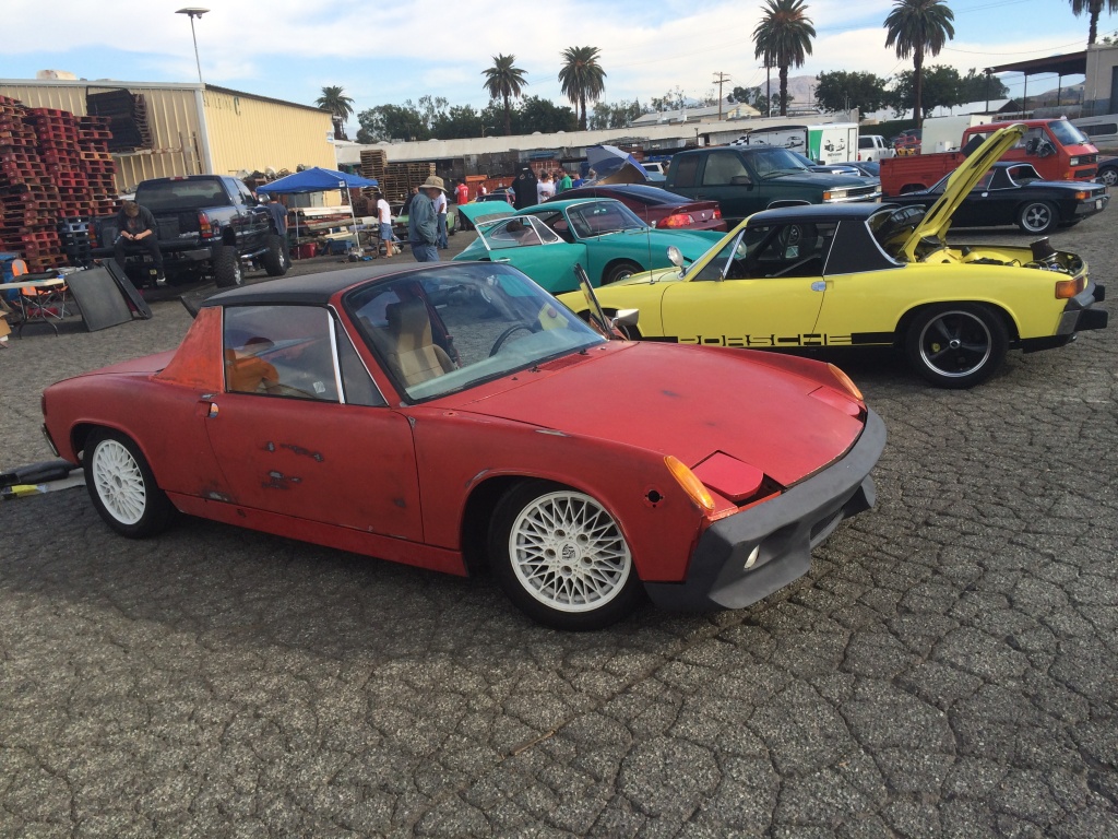
Been awhile since my last update, and have recently accomplished a few things on the car. First things first, i took here on the longest ride of her (new) life, drove all the way to Ron and Glens amazing G&R swap meet, was a fun 40 minute ride. I caravaned the way there with jamie, which was very comforting!

Here she is at the swap meet.

IPB Image

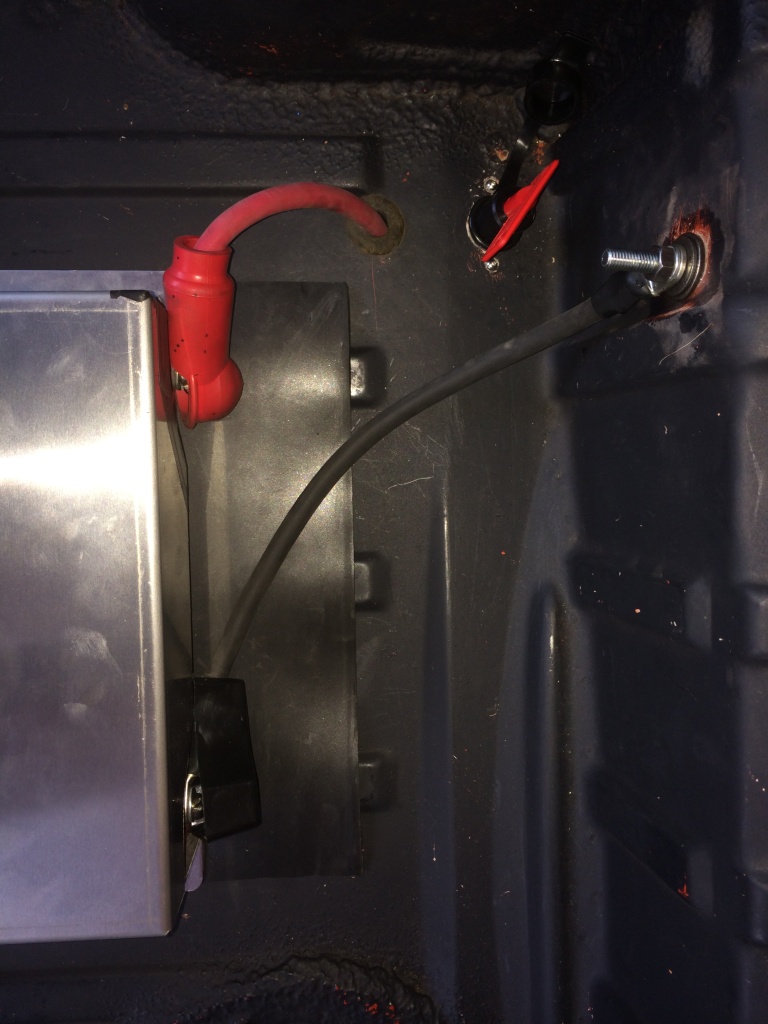
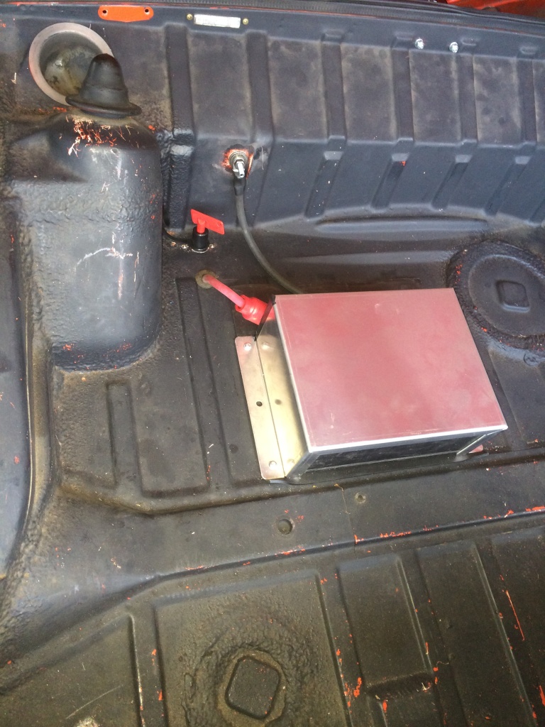
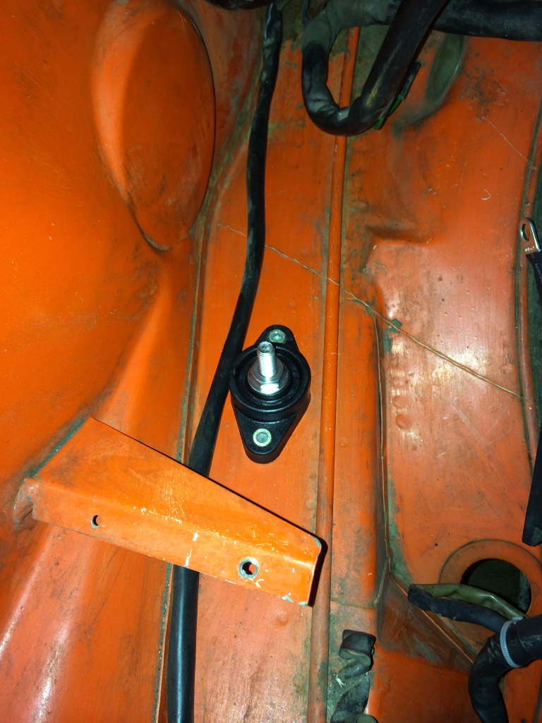
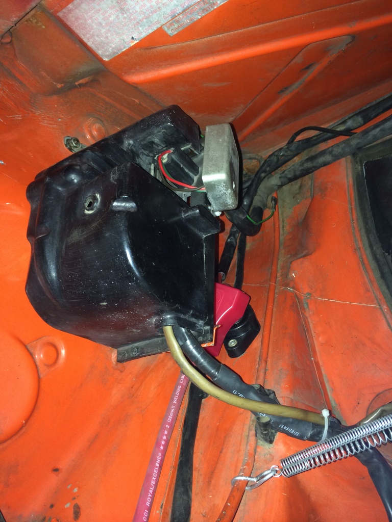
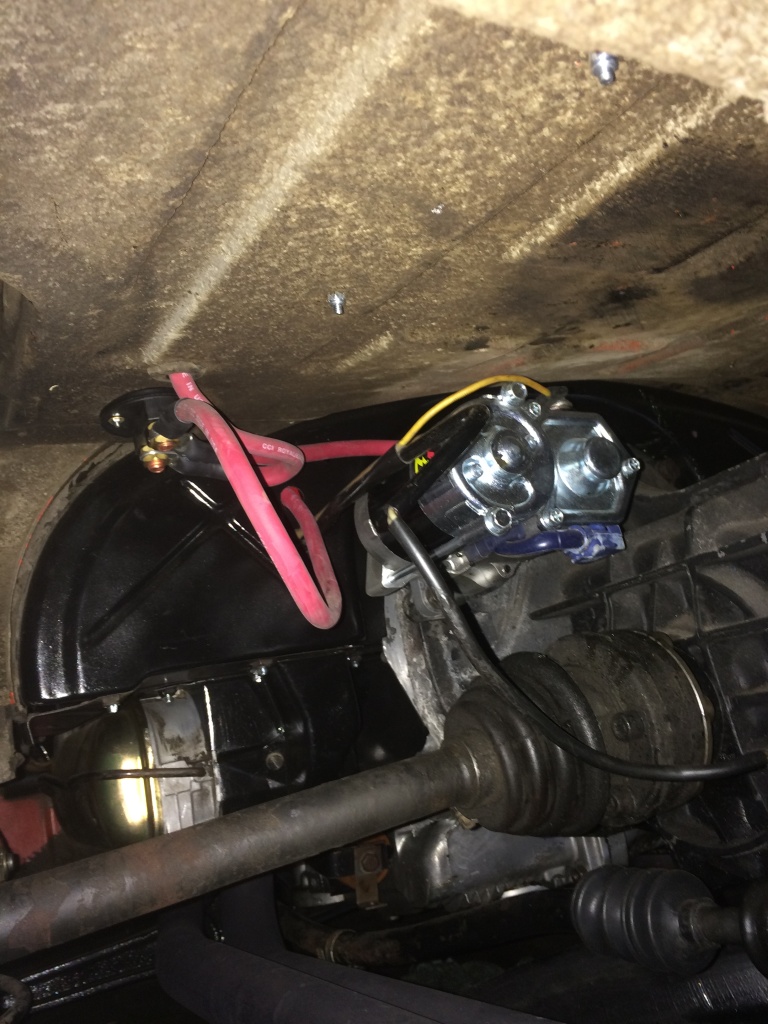
One of the major things recently was redoing the battery cabling the right way. Ordered a bunch of 2 AGW wire and lugs, a terminal post and a battery kill switch (and Jim, lol) Turned out great!

IPB Image

IPB Image

IPB Image

IPB Image

IPB Image

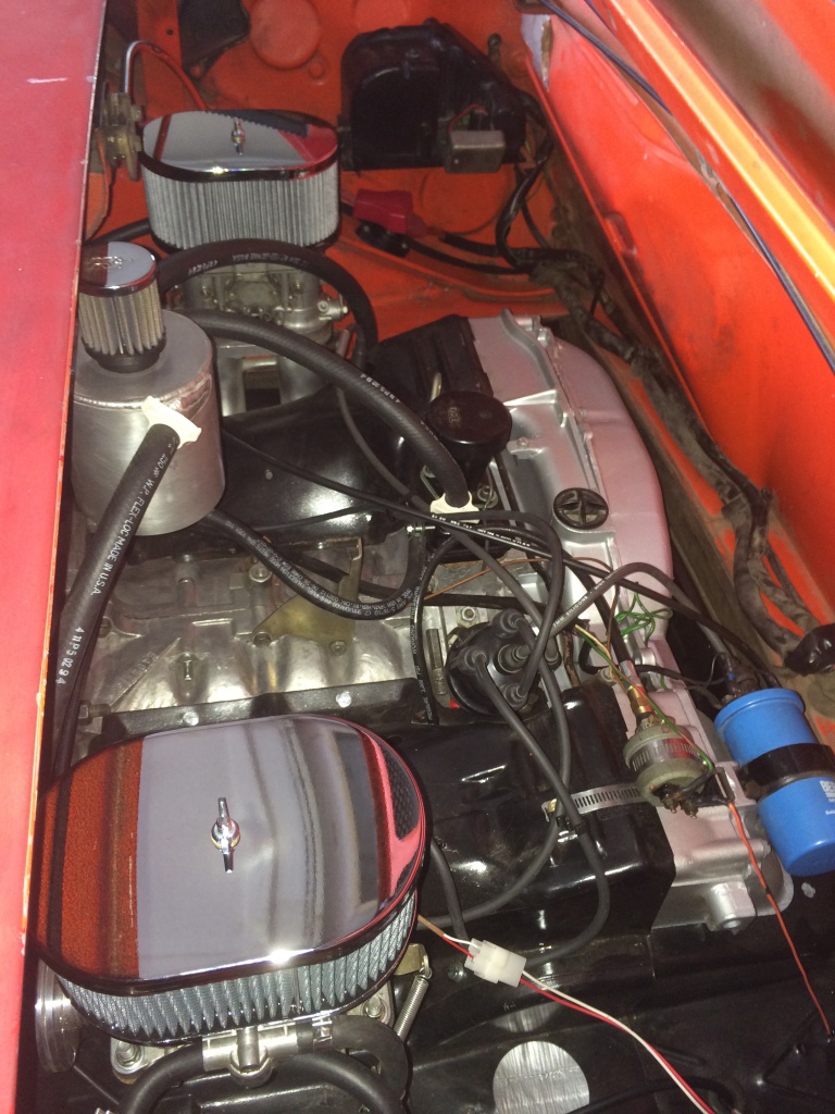
Then today i installed new air filter housings!! so shinny and they have just one single wing nut to remove the top, not four fucking stupid metal clips!!

IPB Image

More good stuff on the way soon!
BMiller
Engine looks about clean enough to eat off of! Keep them coming!
monkeyboy
No more fire hazard! Looking good.
rick 918-S
Coming along nicely!
dfelz
Thanks guys, much appreciated; definitely couldn't have gotten to this point without 914world! beerchug.gif
dfelz
Been awhile since my last update! And its mostly because I haven't done much, but in the past two weeks have started a few projects, but luckily they are all in the same area, and all need the gas tank pulled!

Problem A was a fuel leak right at the tank nut to feed line, not sure if the paper gaskets didnt seat correctly or what, but it was slowly leaking and had to stop. Once the tank was pulled, I removed the nuts/feed lines and noticed a lot of debris crowding the gasket area, which means my assumption was correct, not seating the gasket properly. The inside of the tank looks great though (according to Ethan, i didnt look just took his word for it) so i am just going to plug it up with a little gas inside and give a good whirl to get that grit out of there.

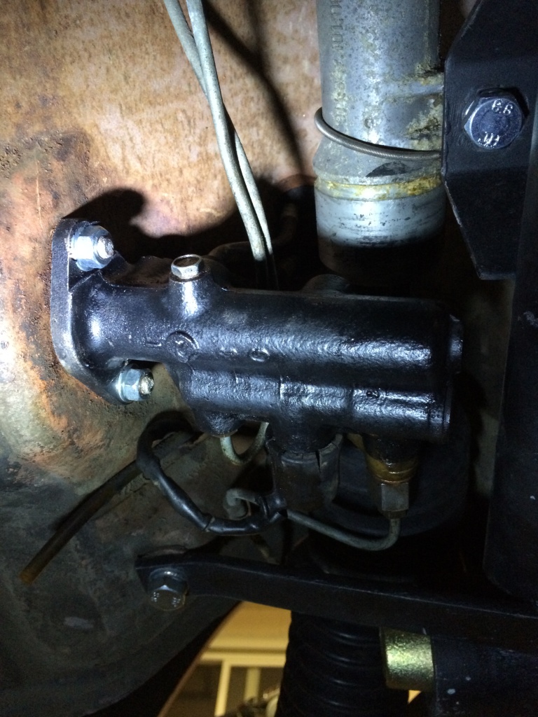
Next item was swapping the stock 17mm MC with a "new" 19mm MC to compliment my larger M-caliper front brakes. Install was a breeze with the aid of Ethan and Jim; and they even bled my brakes for me biggrin.gif biggrin.gif i just had to make sure to keep topping off the reservoir! And sure as shit they did a great fucking job, that brake pedal feels like it could stop a train! I cant wait to actually road test it and not just jack stand pretend test it, haha.

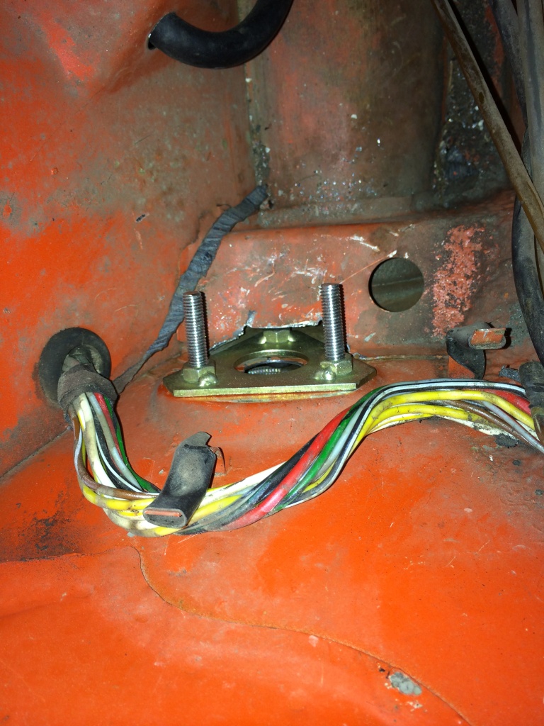
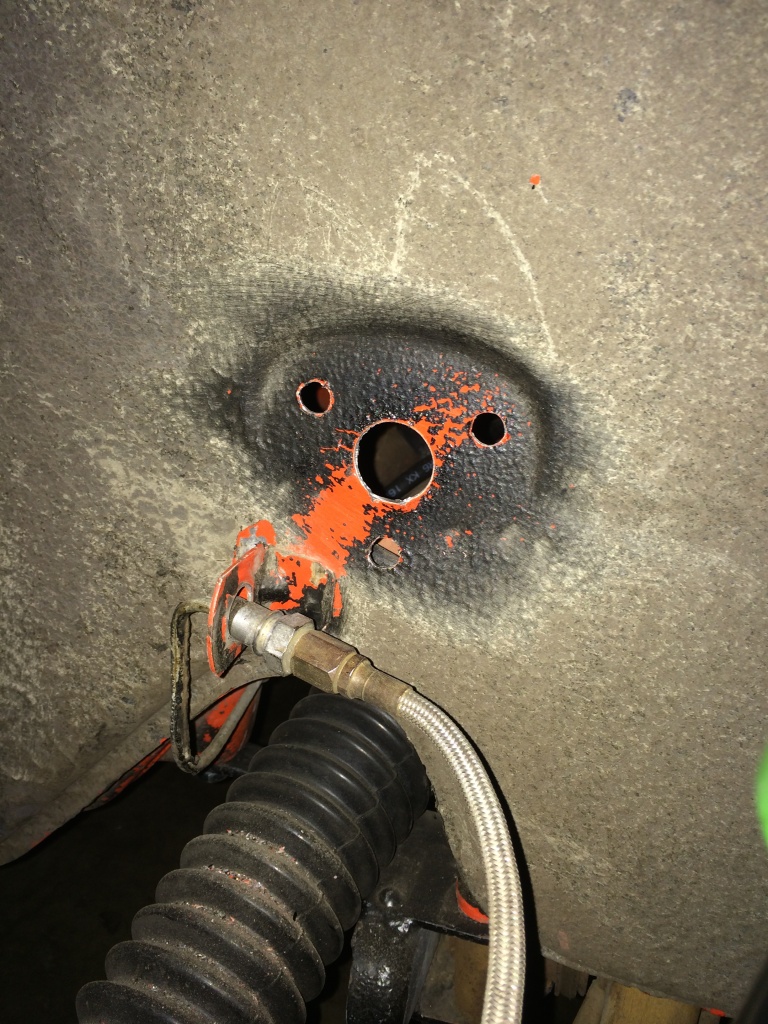
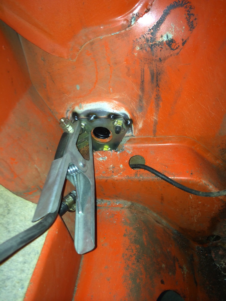
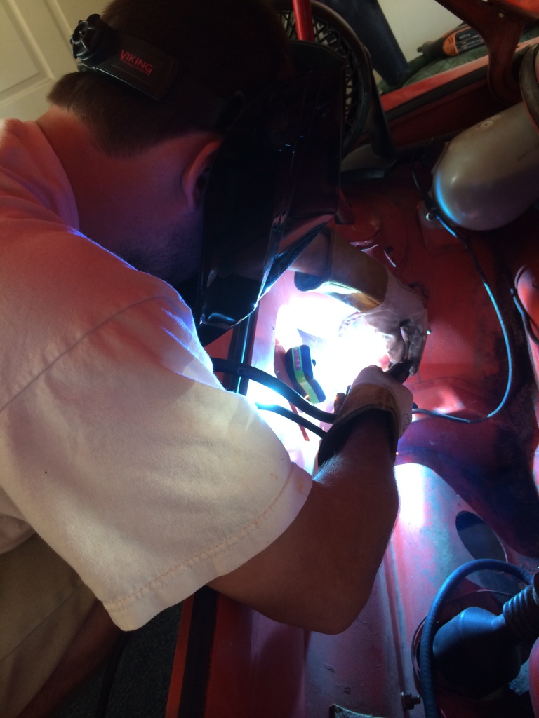
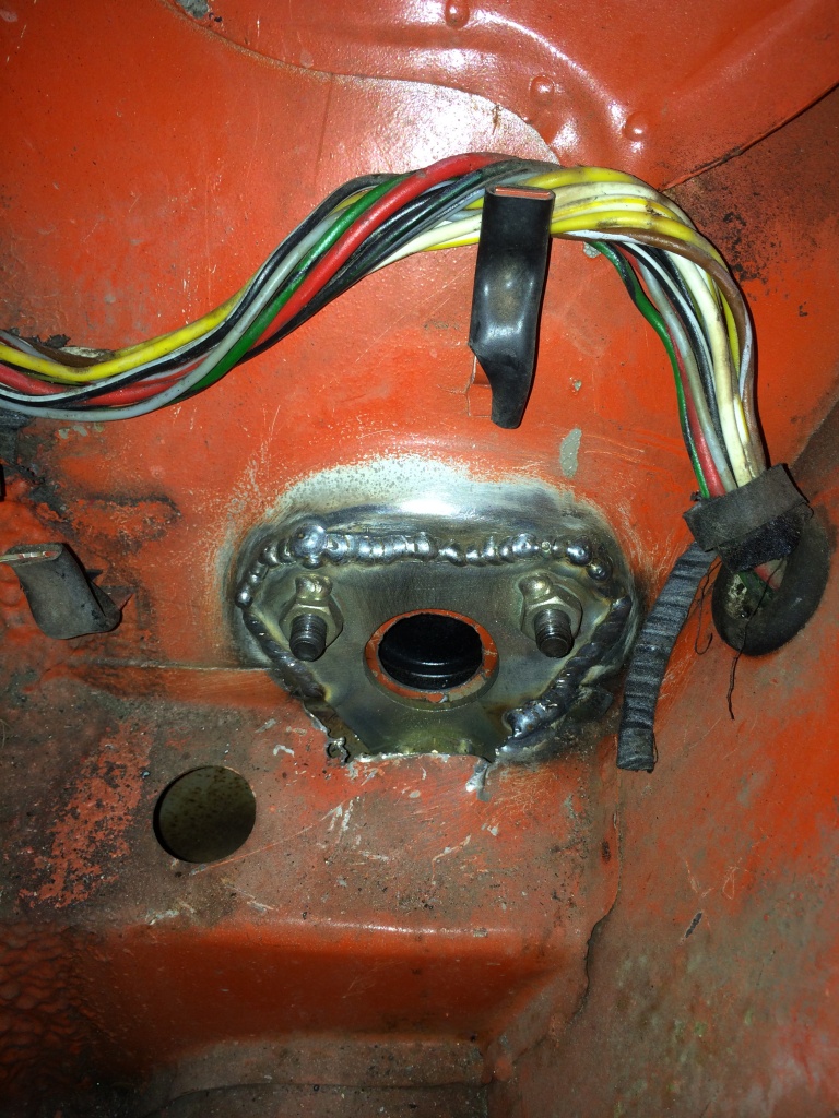
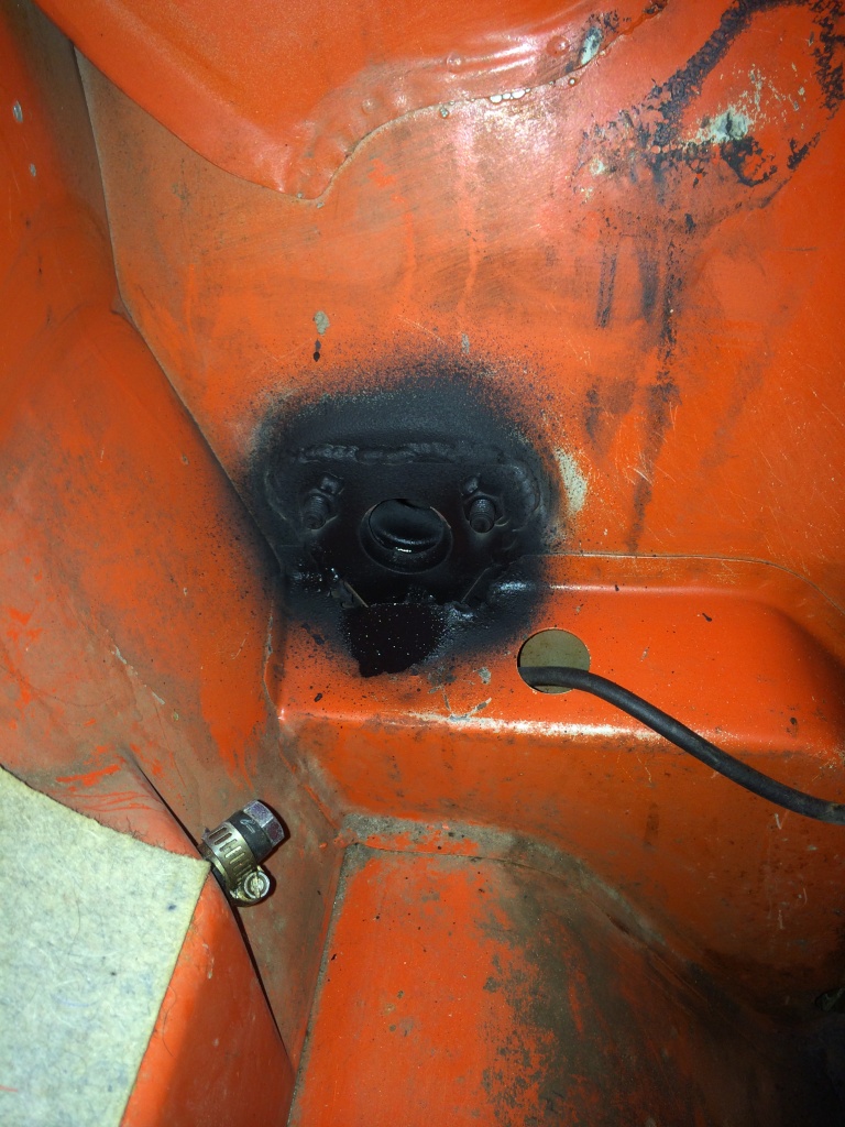
Last item (for this post at least, lol) was the scary retrofit of a front sway bar! Drilling holes into the chassis is never fun, and always scary, but this one wasnt all that bad fortunately. The hardest part was cutting a slot on the shelf in the gas tank side so that the "to be welded in" support bracket could fit and align with all three holes. I used a dremil to cut a line parallel to the shelf, then drilled holes and the two corners and then pried that section up and bent it off. It was tricky, but i have one side completed (minus welding) and the other just about there. Hopefully the welding will take place very soon!!! welder.gif

Thats all for now! here some pictures to cap it all off!

IPB Image

IPB Image

New 19mm MC installed
IPB Image

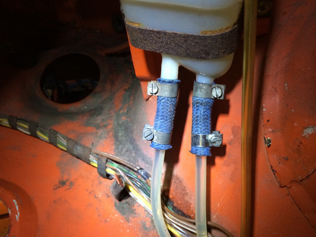
New blue hose too
IPB Image

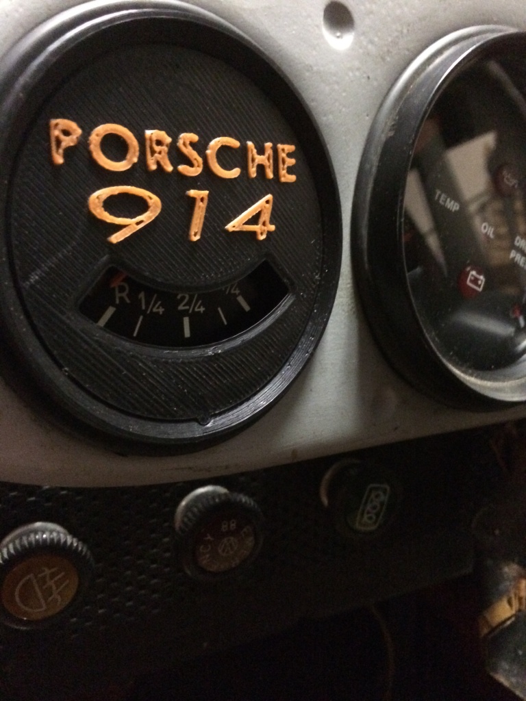
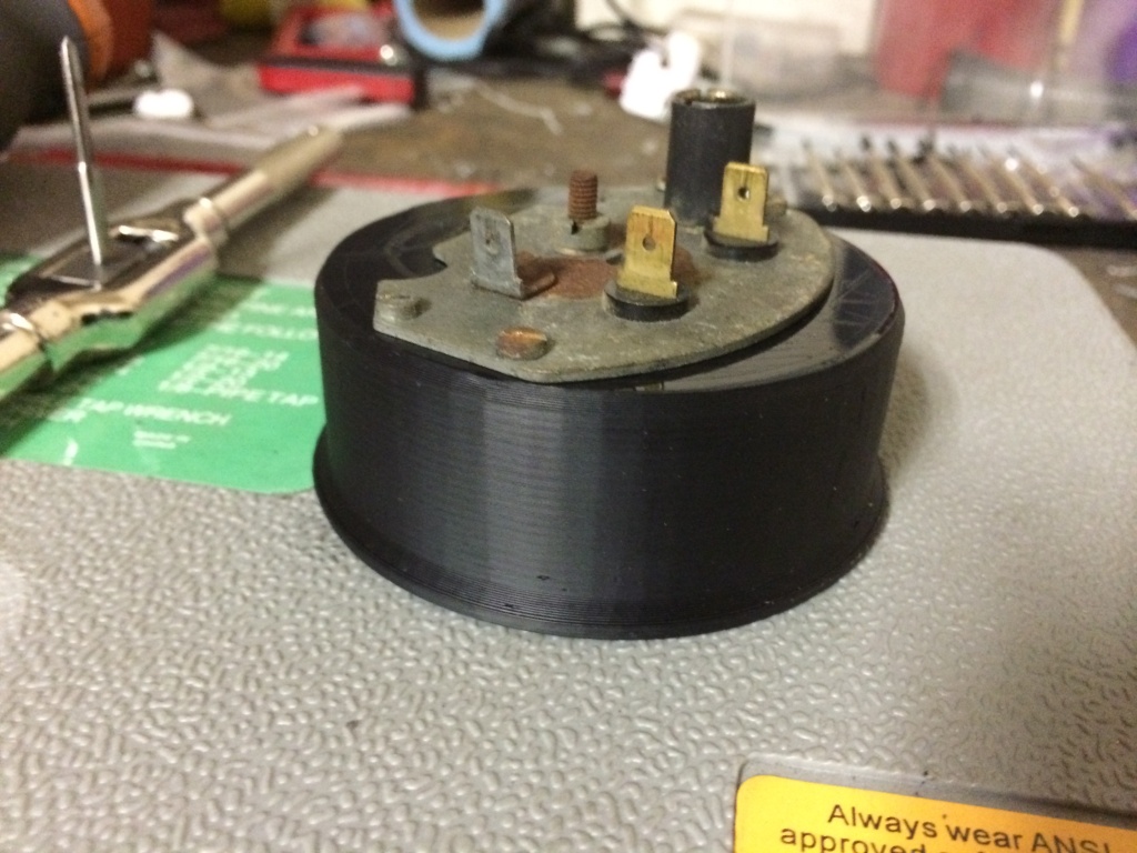
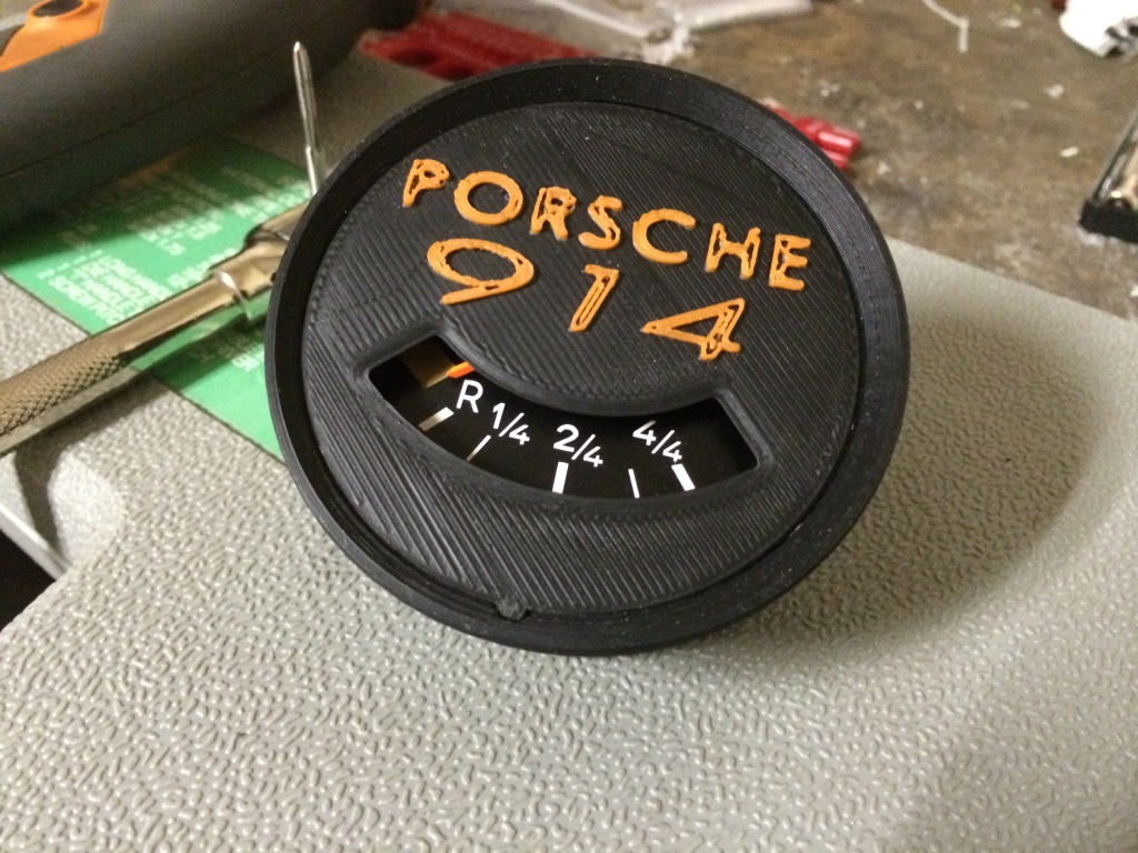
Also!!! I dont think i posted this in here yet, but i have a new gauge in my pod. I 3D printed a custom housing to fit in the smallets hole of my getty dash and mount the fuel level unit itself. Went this route instead of using the stock 911 fuel level/oil level gauge because this is way cooler!!! biggrin.gif biggrin.gif
IPB Image

IPB Image

IPB Image
dfelz
Finally went back for the weekend to my old house where the teener still resides and was able to punch in a few measly hours. Welded in a the mounting brackets and then sprayed primer over the area to prevent rust, then attempted the bar install with new bushings. I got the bar all the way in, just need to center it more, one side has more of the bar protruding from the bushing bracket, need more hammer power smash.gif

Going off to the Caribbean this tuesday for a scuba diving trip, so i wont be working on the car until the beginning May at the earliest. I really feel bad for her, she wants more road time!!! driving.gif

IPB Image

IPB Image

IPB Image

IPB Image

See ya'll in a month!
sean_v8_914
i have an SUV with a tow bar if any one wants me to drag anything back to san diego. I can even bring my 914 flat tow rig
euro911
Well ... anything new to report, young man?

popcorn[1].gif
dfelz
QUOTE(euro911 @ Dec 20 2018, 03:37 PM) *

Well ... anything new to report, young man?

popcorn[1].gif


I wish! I have been organizing my garage and sorting through all my 914 parts though...labeling boxes and such haha. Hopefully will have something to report in the next few months though, we’ll see. Thanks for the motivation though!
Mendivil26
QUOTE(dfelz @ Feb 13 2013, 08:07 PM) *

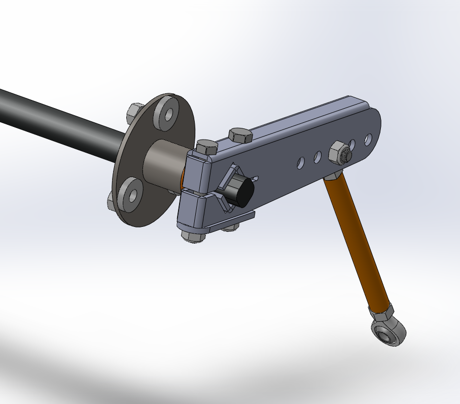
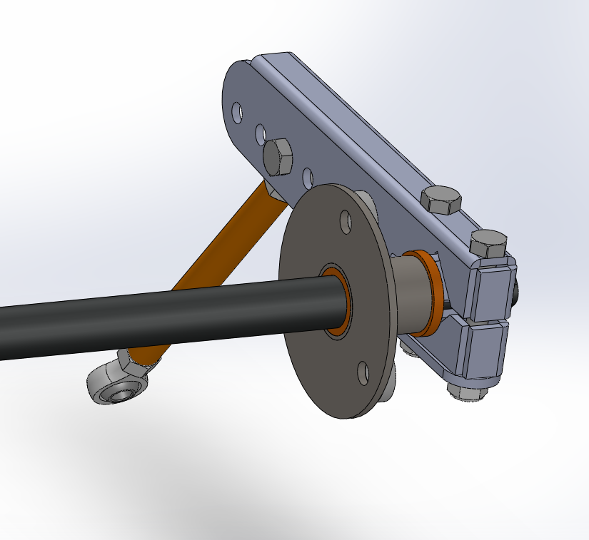
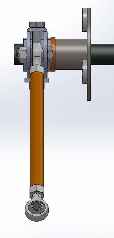
Ok so I have my thru body sway bar modeled up in Solidworks (So wish I had ProE, my last job used it and it was sooooo nice, too bad its a 10K license and my student edition of SW is free.99) I am also going to model the control arms so that i can do a motion simulation and geometry analysis at the different linkage holes. If this was next quarter i could also do a full fledge FEA analysis in Nastran, but since i am not taking finite element analysis until next quarter, the basic knowledge i have of solidworks FEA simulation should give me a good idea of week points in the components and where all the stress concentrations will be.
My design concept was to take the OEM arm, make it adjustable, add the 930 style 90 degree through brackets for more stiffness in part and less chance of rounding the square design, and use spherical bearings on the drop link (top spherical bearing will be right hand thread, bottom will be left hand thread, this will make adjustment super easy by just having to loosen the jam nuts on both sides and then just spinning the drop link tube to adjust the tension/compression.) The clamping method is the same style the stock one uses, i like it more than other methods i have seen on aftermarket ones that have just one bolt on the end. Two bolts with the bar in between distributes the clamping force to ensure all four flats on the bar receive equal forces. I also designed a new bushing bracket so that i could use a a custom oil-impregnated brass bushing. its a simple flange style bushing but it will be pressed in from the wheel side. I will also have some kind of rubber washers in between the back of the bushing bracket and the frame sheet metal. Since the car this will be going on without a stock thru body bar i will be making a backing plate for the gas tank side with the nuts welded on for capture of the 3 M8 bolts.
The backing plate, bushing bracket and link arm will all be laser cut 1/8" 1018 cold rolled steel (with the link arm obviously being bent into formation and then tig welded together. Will hopefully have them normalize since all the components will see some welding time, and will then be plated.

Please keep in mind this is my first run at this system and would love everyones input and considerations that i may have overlooked. Just for reference, there are 5 holes for adjustment, the middle one is the exact distance the single stock one is at. I worked in the medical device industry for 6 months full time for an internship and i was doing hardware and tooling design (designing components for the manufacturing line and testing systems for pacemakers and implantable defibrillators) so i have some experience doing design work, am also on the SAE electric team. But like i said, i really want your input, so feel free to ask any questions you like and give any commentary.

IPB Image

IPB Image

IPB Image

I can get more snap shots too! beerchug.gif


Sorry about reviving an old thread, but by searching the keyword "Solidworks" rendered this result and I noticed you said you were modeling control arms.
Did you ever get to model any other parts of the suspension besides the sway bar? I'm building an off road Baja 914 and would like to design some longer travel control arms, and it would save me a lot of time if someone has the model already.

euro911
I think David (@dfelz ) finished his engineering courses at Cal Poly, so I'm not sure if he still has access to the cool machines and tools they have there confused24.gif

That reminds me though ... I have a pair of the arms and drop links that he made. I blasted the arms last year, but I still need to have them painted, plated or powder-coated idea.gif
dfelz
Hi ( @Mendivil26 ), sorry I don’t have the control arms modeled up unfortunately, and Mark is also correct in the fact I no longer have all the great tools and CAD software that was available when I was at CalPoly. I sure miss that.

Mark I also never got around to installing my sway bar and mounts dry.gif but soon I hope
barefoot
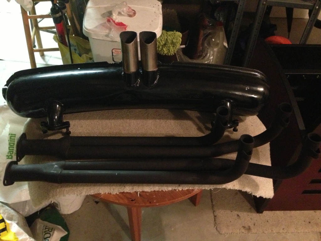
[I also picked up this sexy exhaust this morning. 2.0L straight pipe headers to a 911 muffler. The muffler had its original single side outlet cutoff and welded shut, then a dual tip center outlet weld on. I cant WAIT to mount this puppy!
IPB Image

Sorry for the long post, hope you enjoyed!

Thanks for all the help and support everyone! beerchug.gif
[/quote]

I think your un-equal length straight headers are going to crack because the different lengths will expand differently creating a fatigue crack cyclic stress condition. With both ends fixed the longer tube wants to expand more than the shorter one will let it.
A typical fatigue machine.
dfelz
Well Hello 914 Community!! It has been quite sometime now, and I have felt the need to get my 914 back up and running. As an update, I had an engine issue about 5 years back now, and it has been sitting since then... other things in life got in the way, but id really like to get it back up and running again, then finish the job and get bodywork, paint and interior done as well once she is running again.

After taking the valve cover off on the driver side, it was very apparent what when wrong years back, had a valve spring failure, on cylinder #2 exhaust valve. This was probably a major oversite on my part when building the engine up, but I didn't replace the valve springs, and looking back now at some old pictures from the rebuild I can see that there is visible rust on the springs, probably from sitting in the engine for years unused before I bought and rebuilt it. So a $100 worth of new parts likely could have saved me form this mess... not sure why I didn't replace them... Lesson learned!

So here we are now. My plan is to drop the engine, take the heads off and inspect everything. Feeling the valve as it sits now, the valve guide still feels nice n snug on the valve stem, certainly no wobble or looseness. Hoping (praying) that there isn't bad damage to the piston head. This incident happened while tuning the engine in the garage, so we cut the engine as soon as we heard the large bang sound, but will find out soon what domino affect it had on surrounding parts. Don't see any damage to the rocker arms and that assembly, and all pushrods look to be in great shape, along with pushrod tubes.

Problem is that I cant find all the parts of the broken spring and one half of the valve retainer. Looked in the pushrod tubes and noting in there. My gut says that I need to fully crack the case open and clean out the inside to make sure there isn't any remaining pieces of the spring floating in the engine case, does that sound like the smart thing to do to everyone else as well?

From the visible damage we can see now, which doesn't look drastic, on the spring seat surrounding the valve guide, does that look like it needs to be machined or repaired, or can that be used as is?? Obviously replacing all the valve springs, retainers, and valve hats. Should I replace all the exhaust valves themselves as well while I'm in there?? I have been reading they have a shorter life anyway?

Any and all comments / suggestions welcome.

Click to view attachment

Click to view attachment
This is a "lo-fi" version of our main content. To view the full version with more information, formatting and images, please click here.
Invision Power Board © 2001-2024 Invision Power Services, Inc.