Redux reactions are so fun to repair.
Looking good.
You've been busy! Nice progress and work. Fun thread to follow.
Really nice work. 
Judging by pictures, I don't suspect your work space is heated. Impressed that you're still moving along during these winter months.
Judging by pictures, I don't suspect your work space is heated. Impressed that you're still moving along during these winter months.
That’s looking really nice Antione. What a tremendous amount of work you’ve done. Impressive mate. Going to be one solid 914 chassis.
Keep it coming!
Keep it coming!
Thanks a lot guys, support is really appreciated ans help getting things moving!!
@Superhawk996 : you're right, no possible heating, so it is currently 0°C in the shop but motivation helps against the cold temperatures ! (And I bring home parts for example to paint).
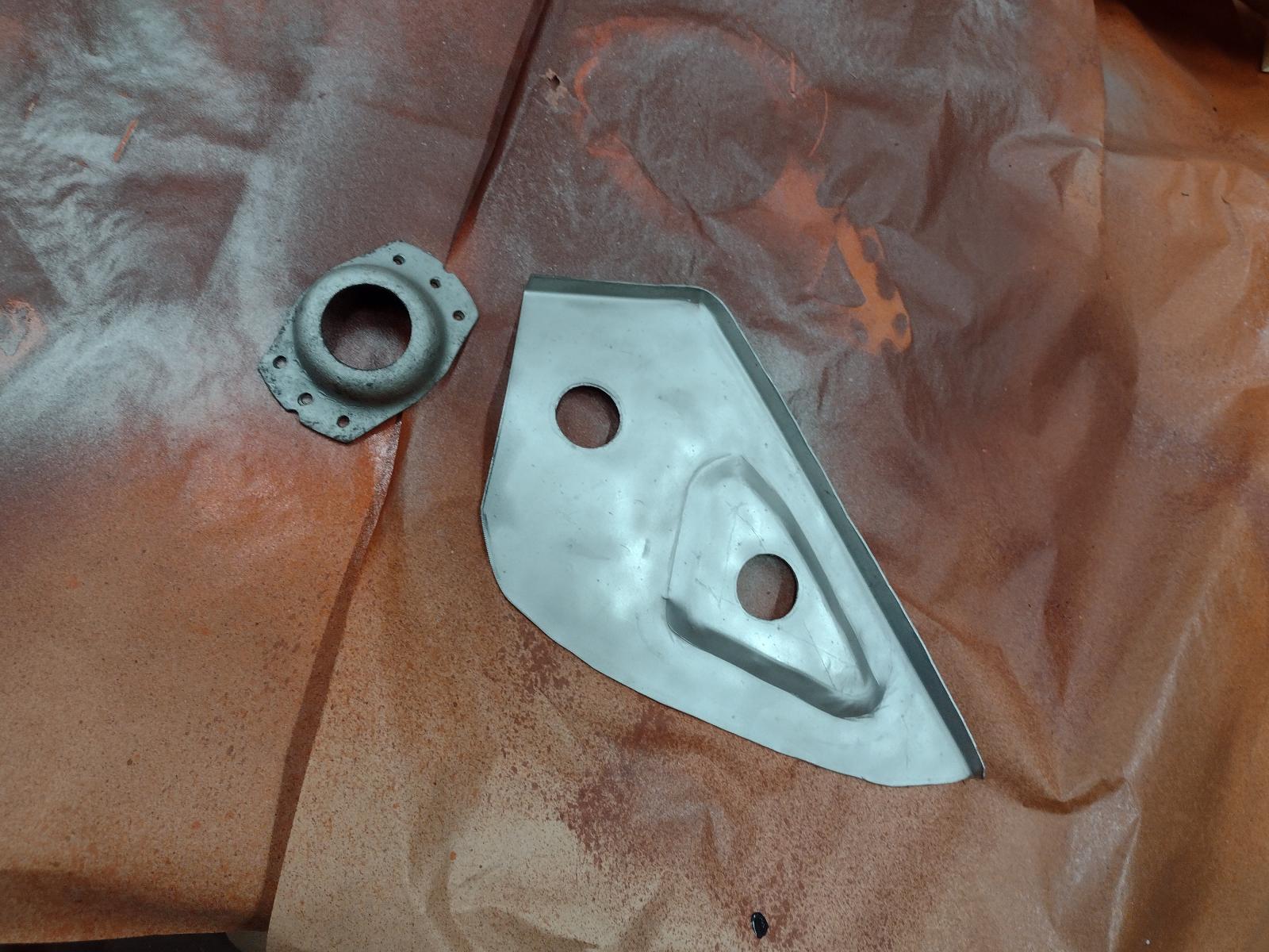
Next update!
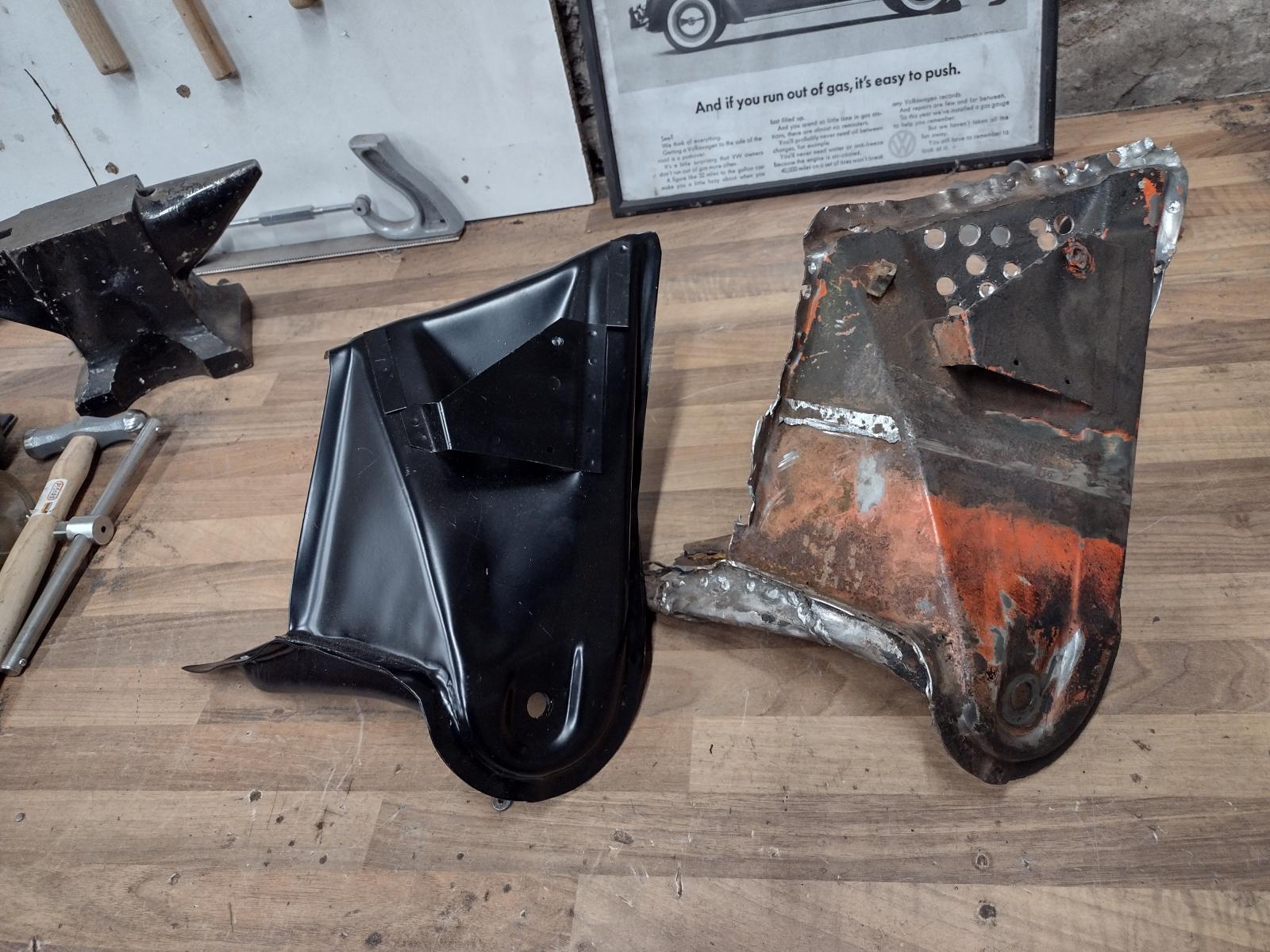
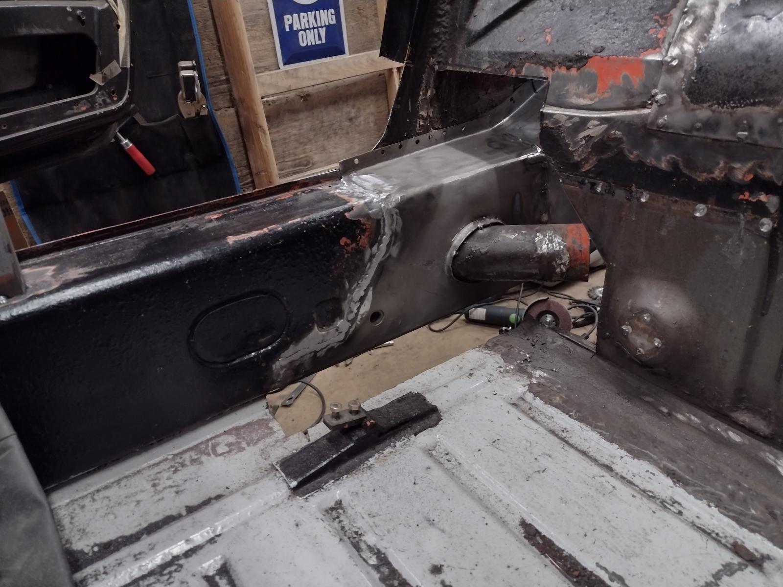
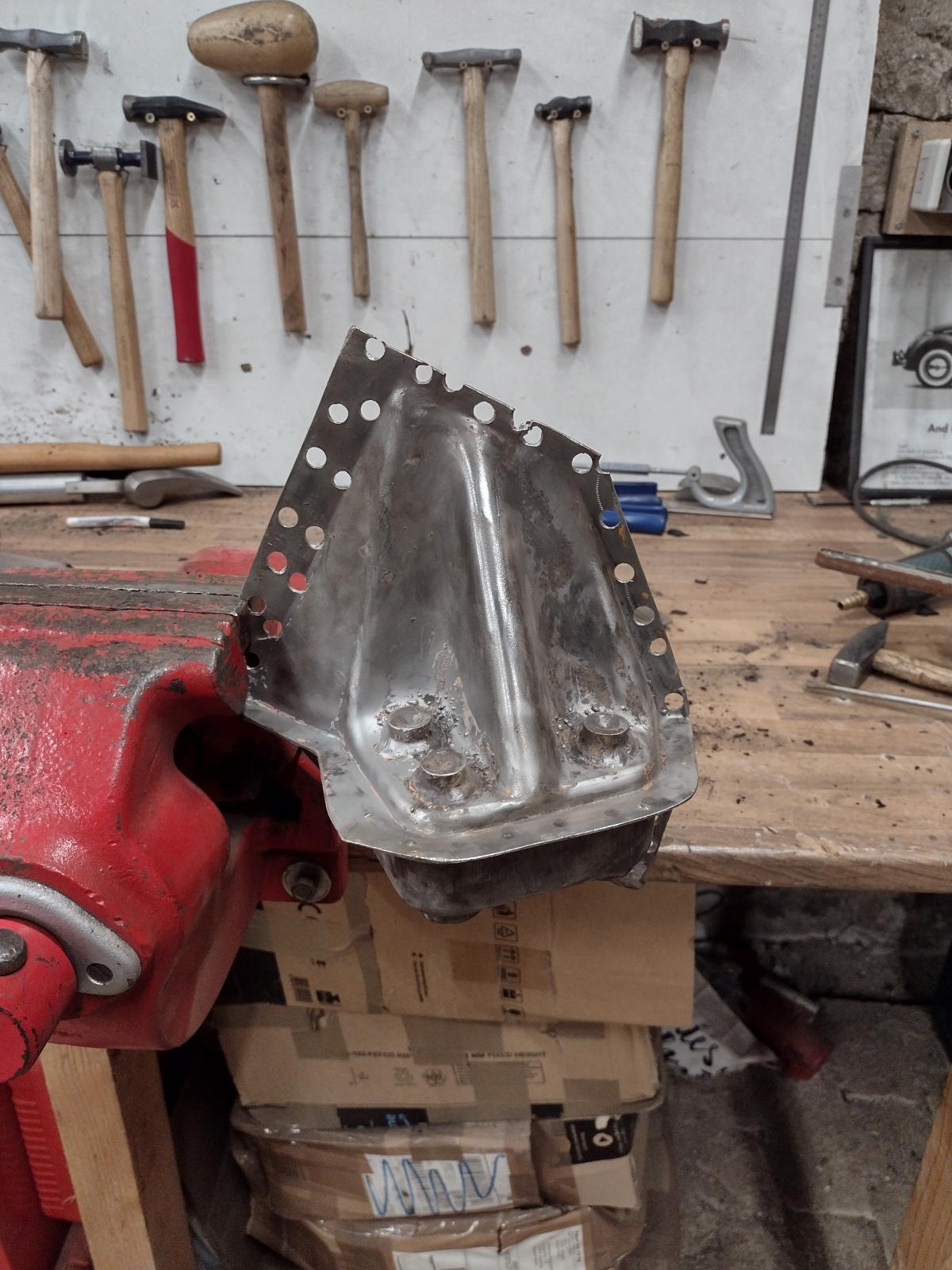
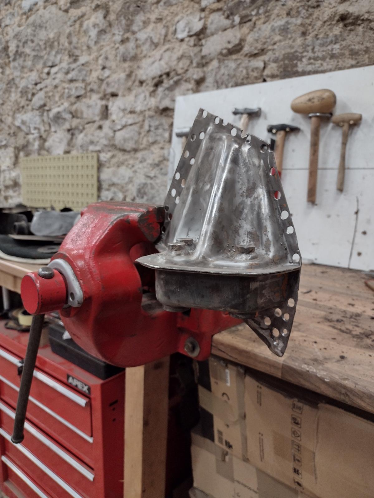
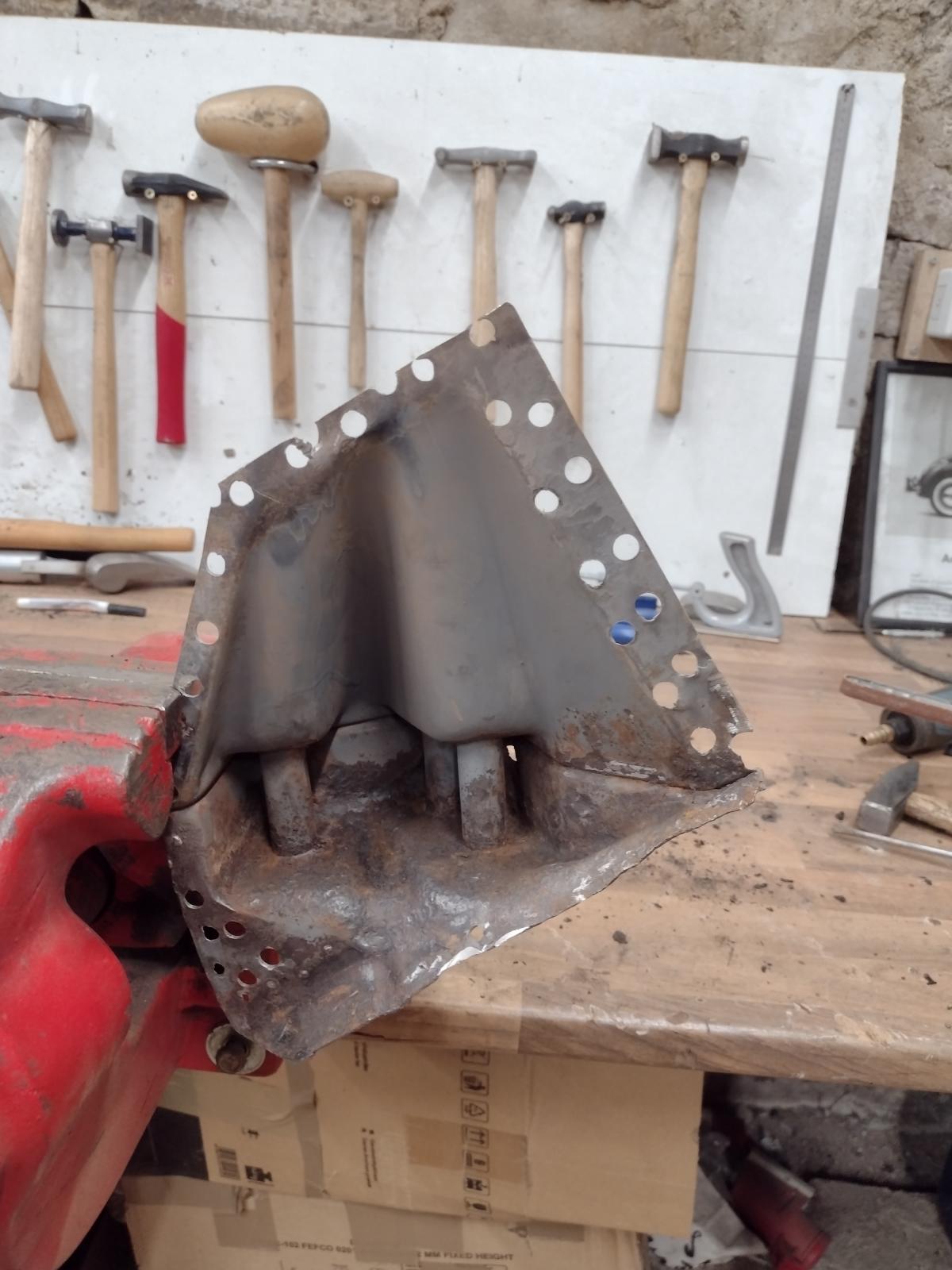
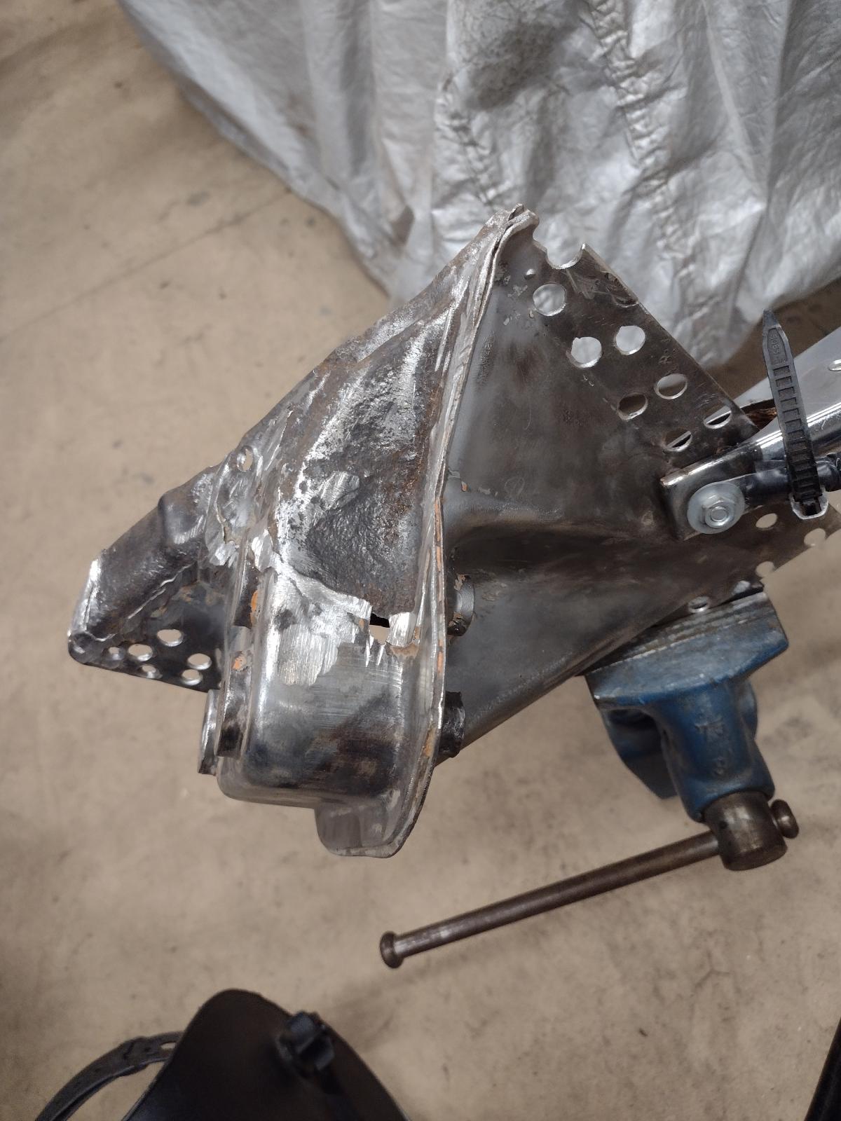
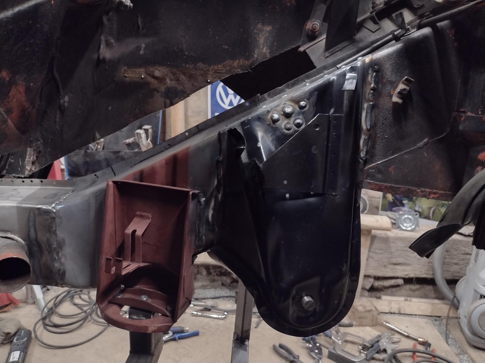
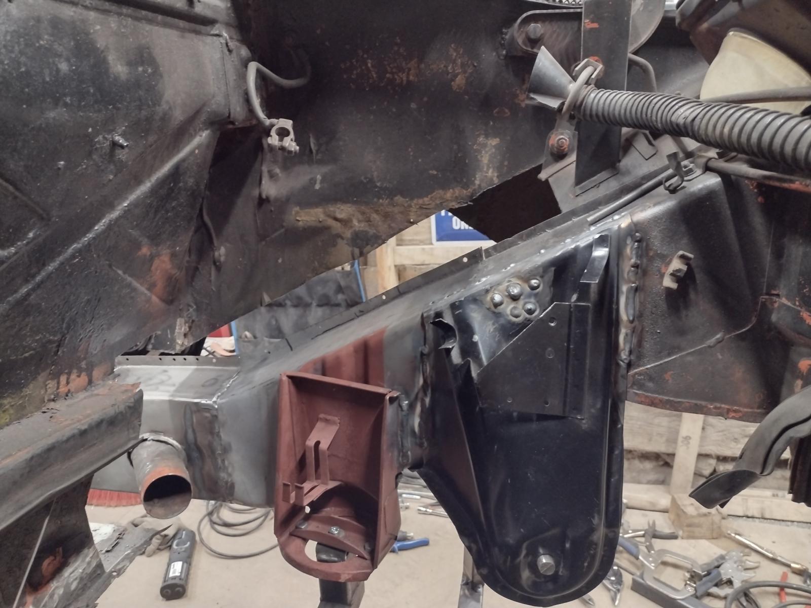
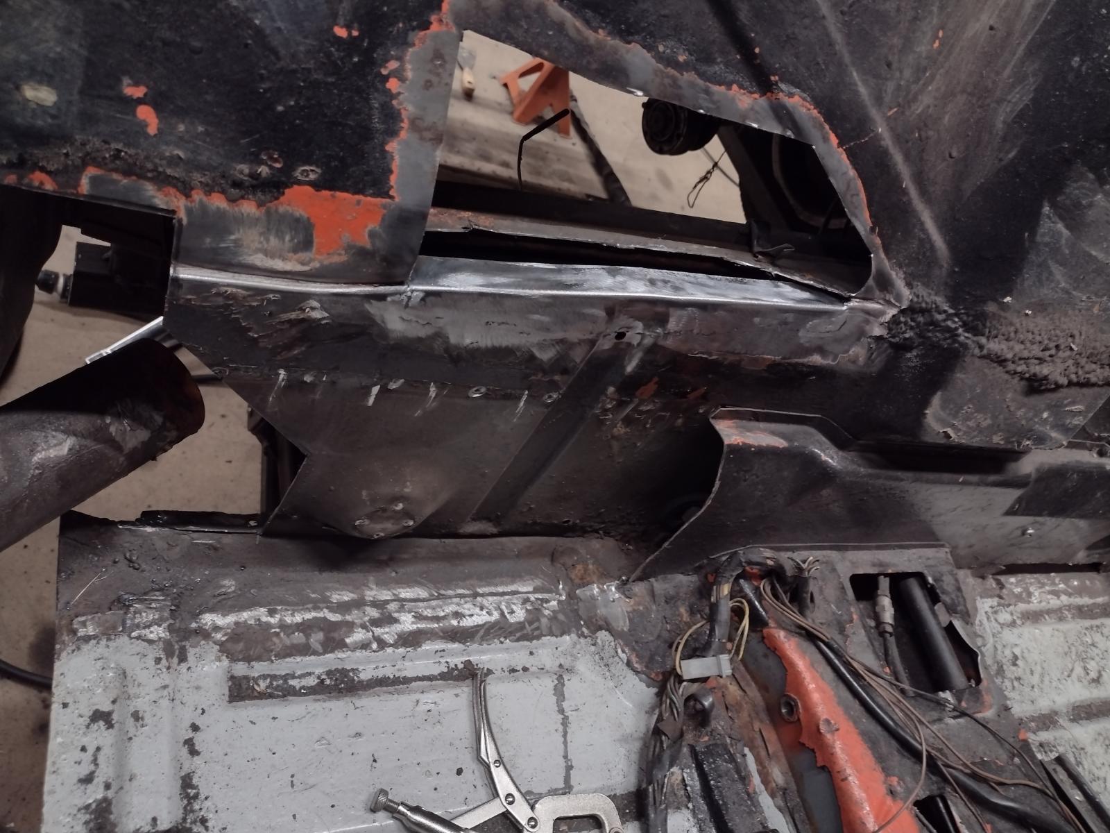
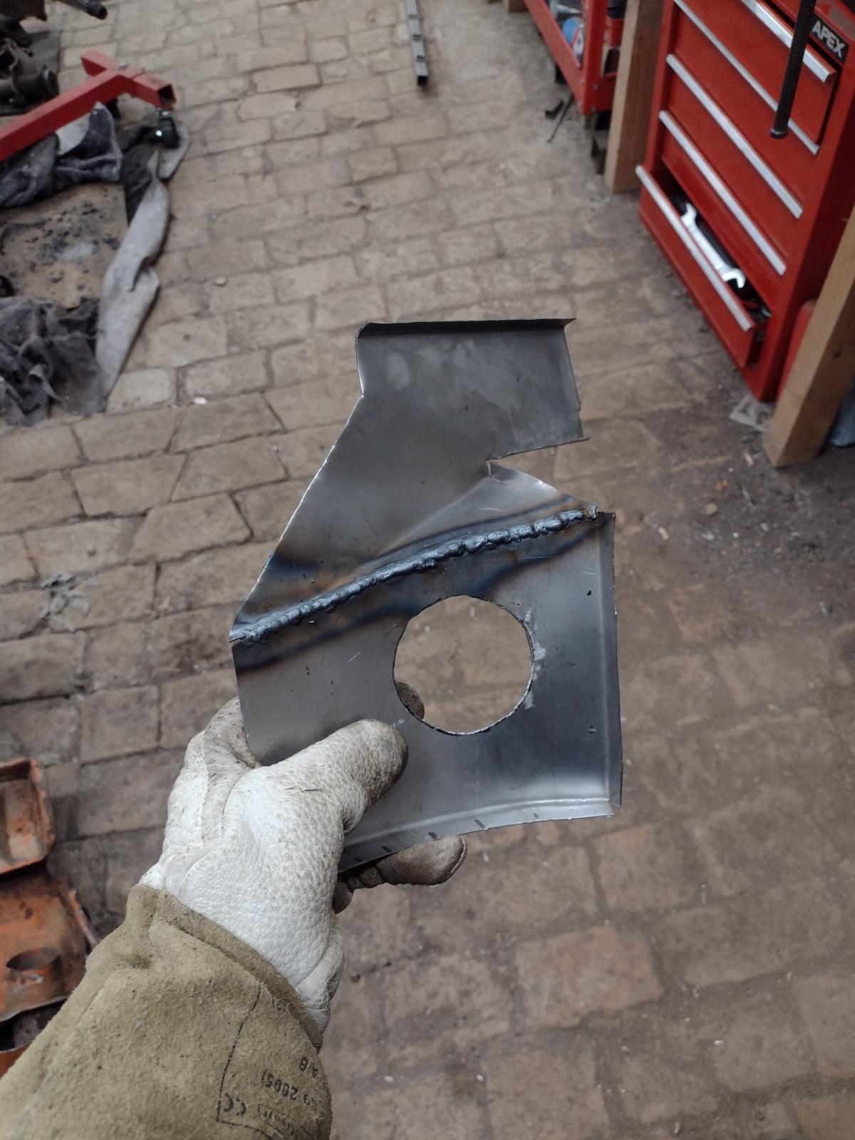
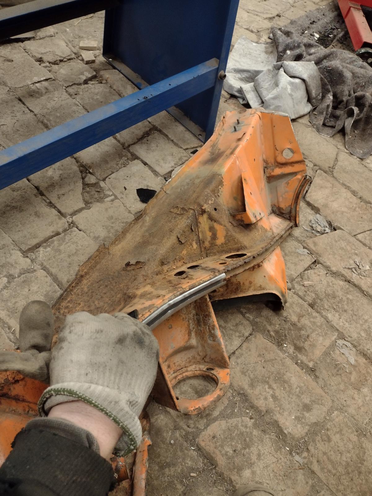
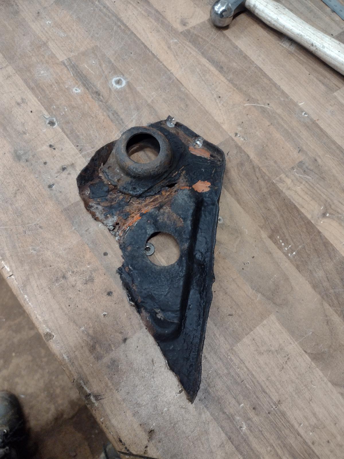
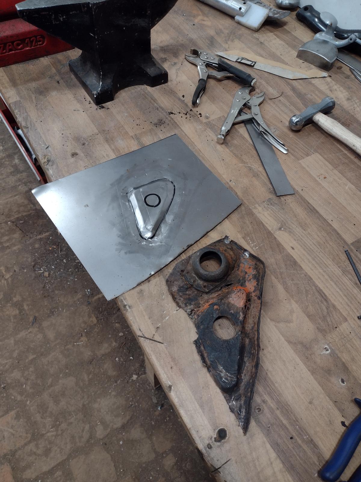
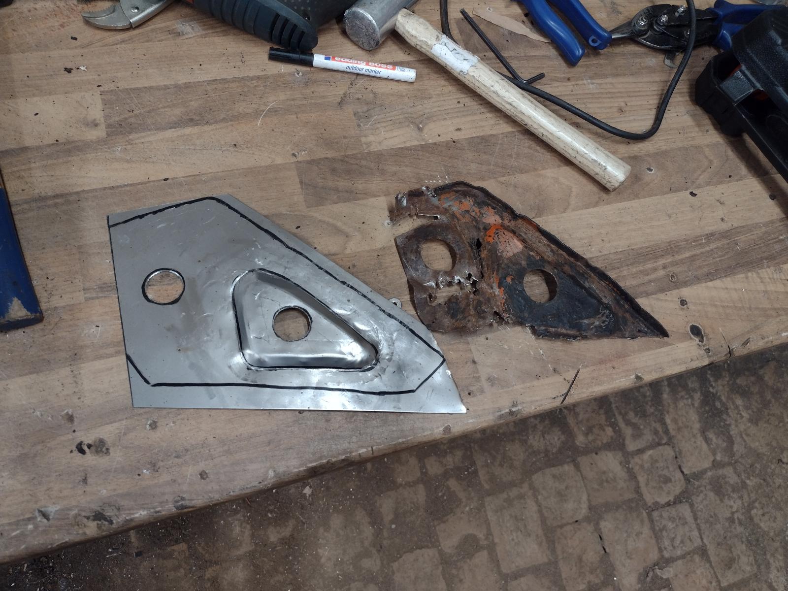
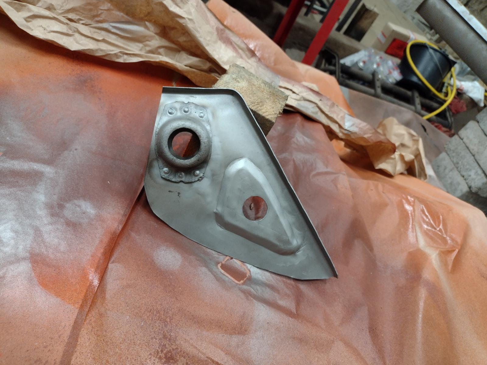
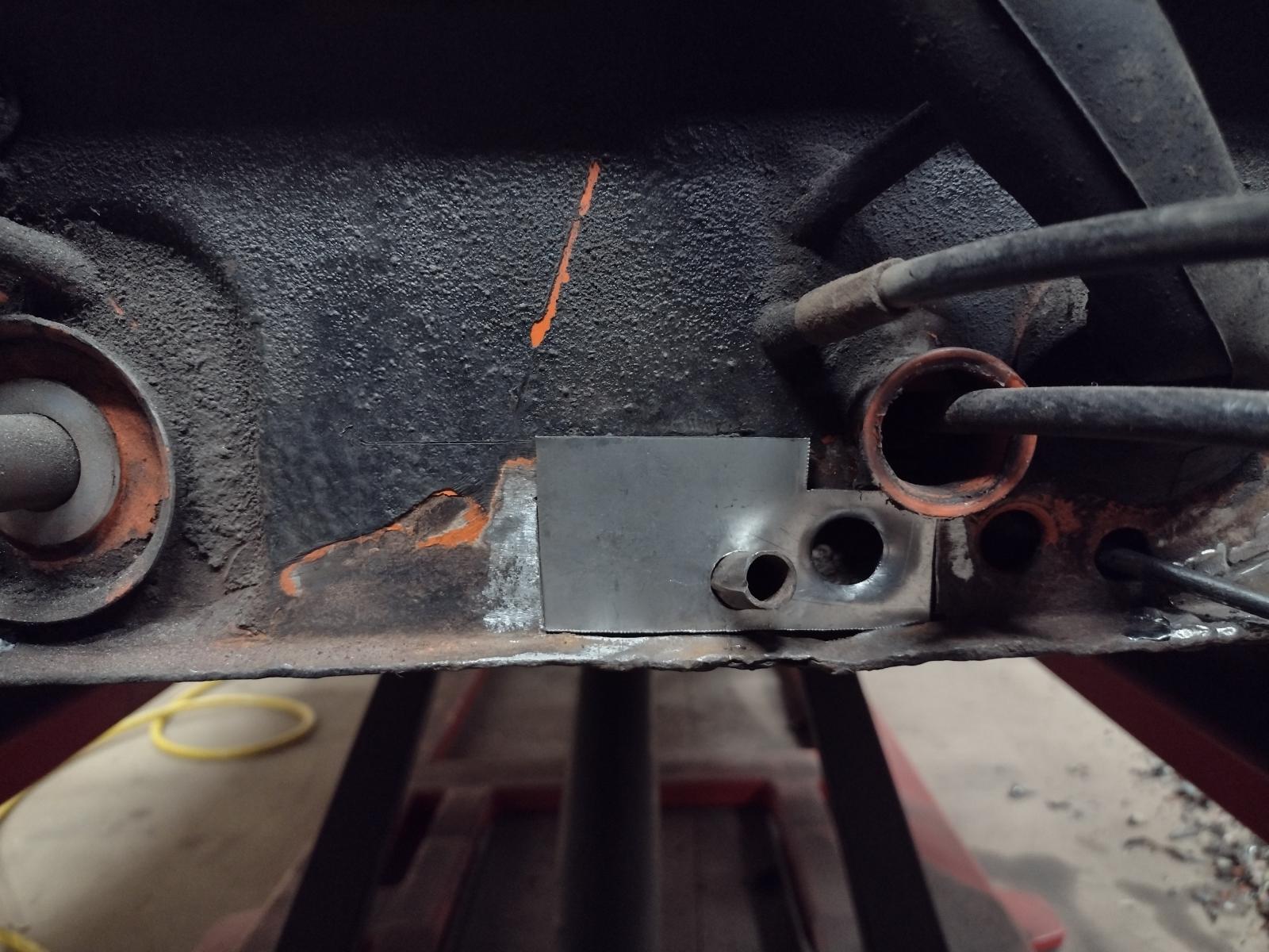
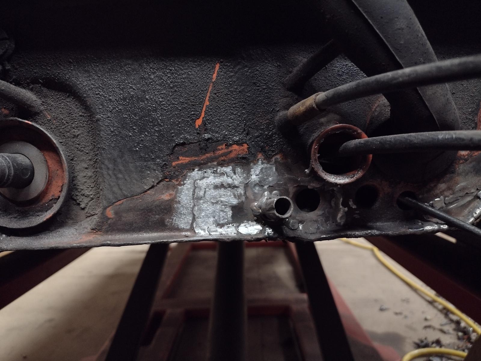
I welded the repair part on the engine mount, now it's ready to be put back on
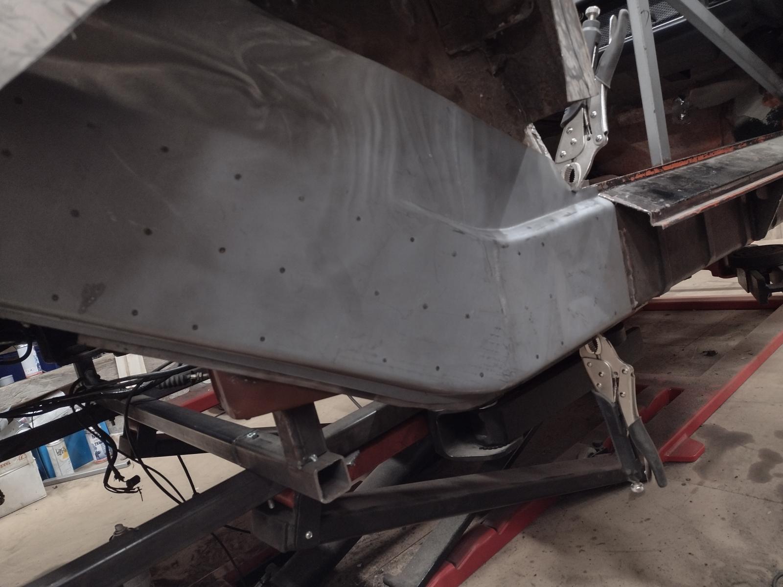
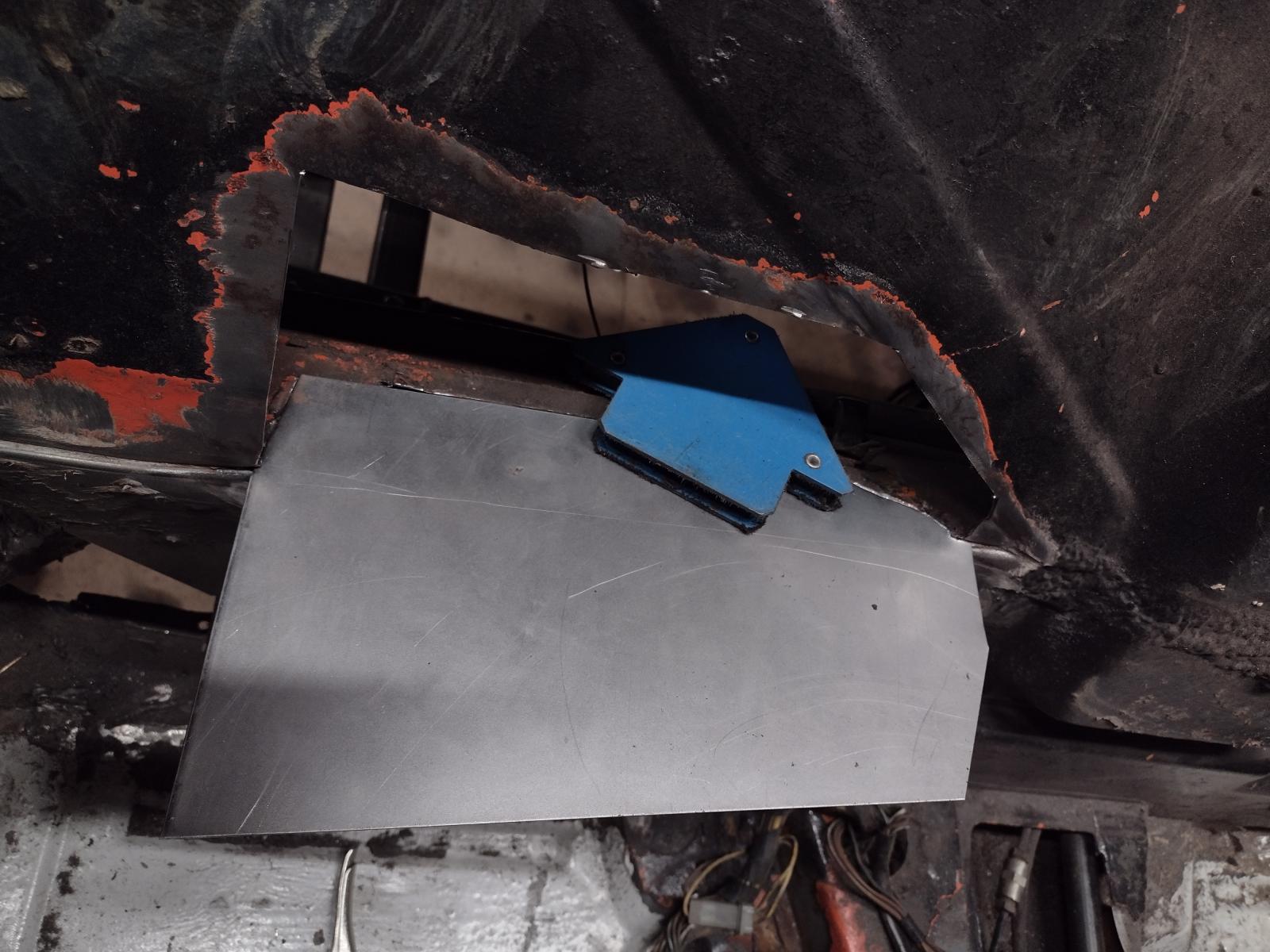
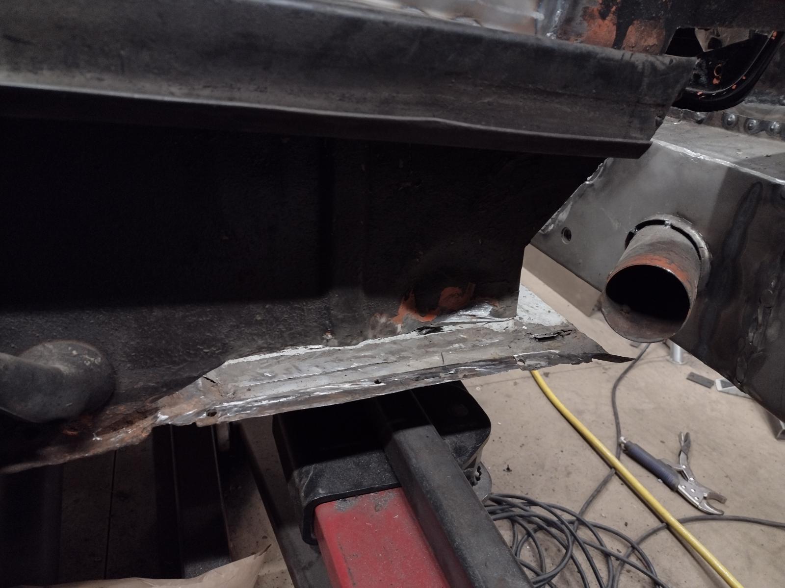
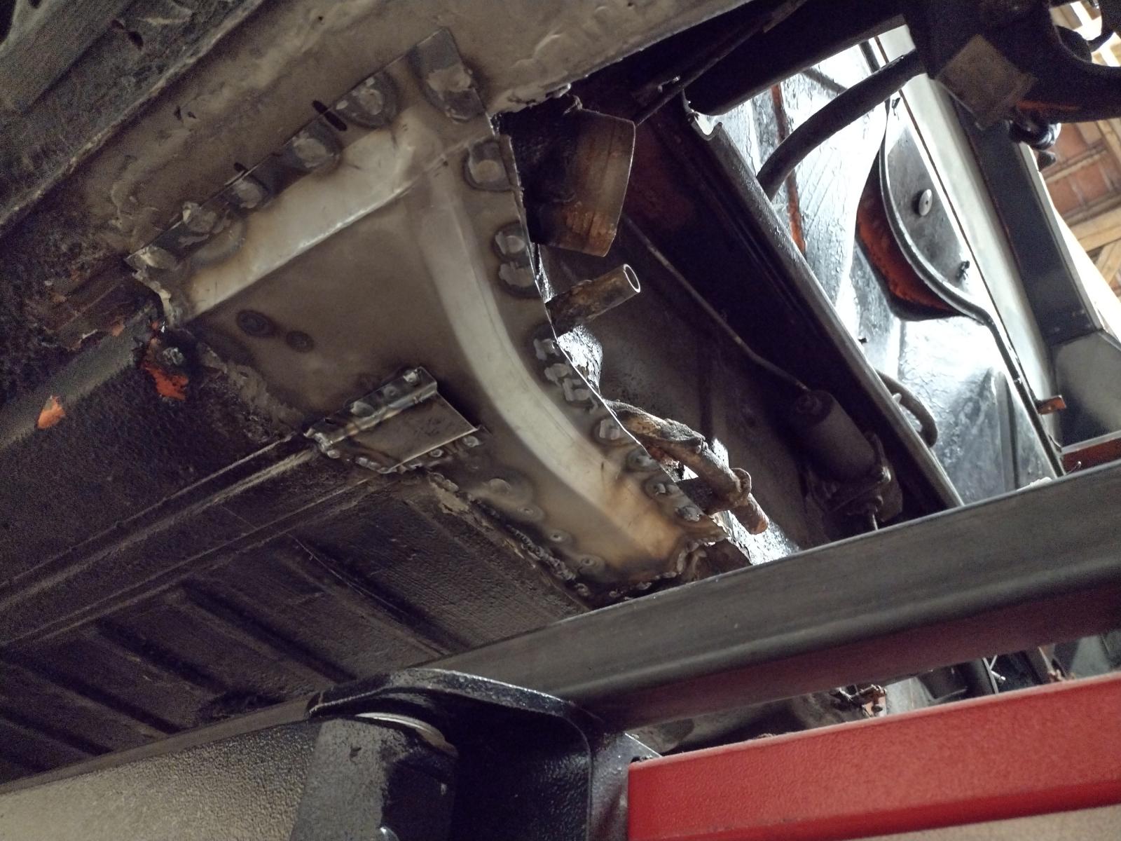
Then I started the adjustment on the inner long. First I put a lot of thoughts on were to make the connection and here was the best place I think, so let's cut:
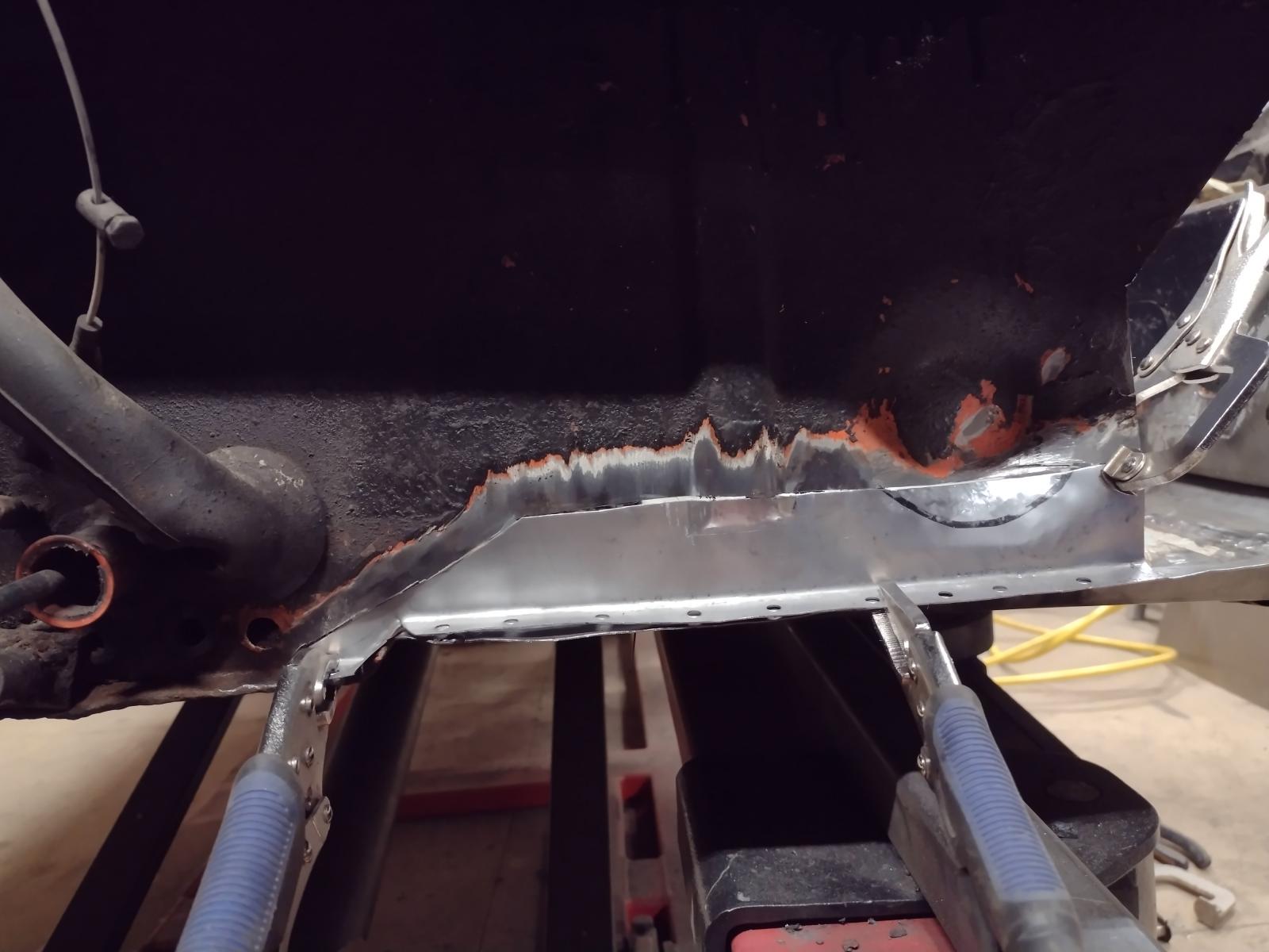
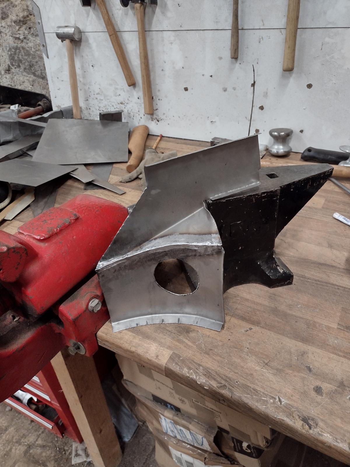
And adjust:
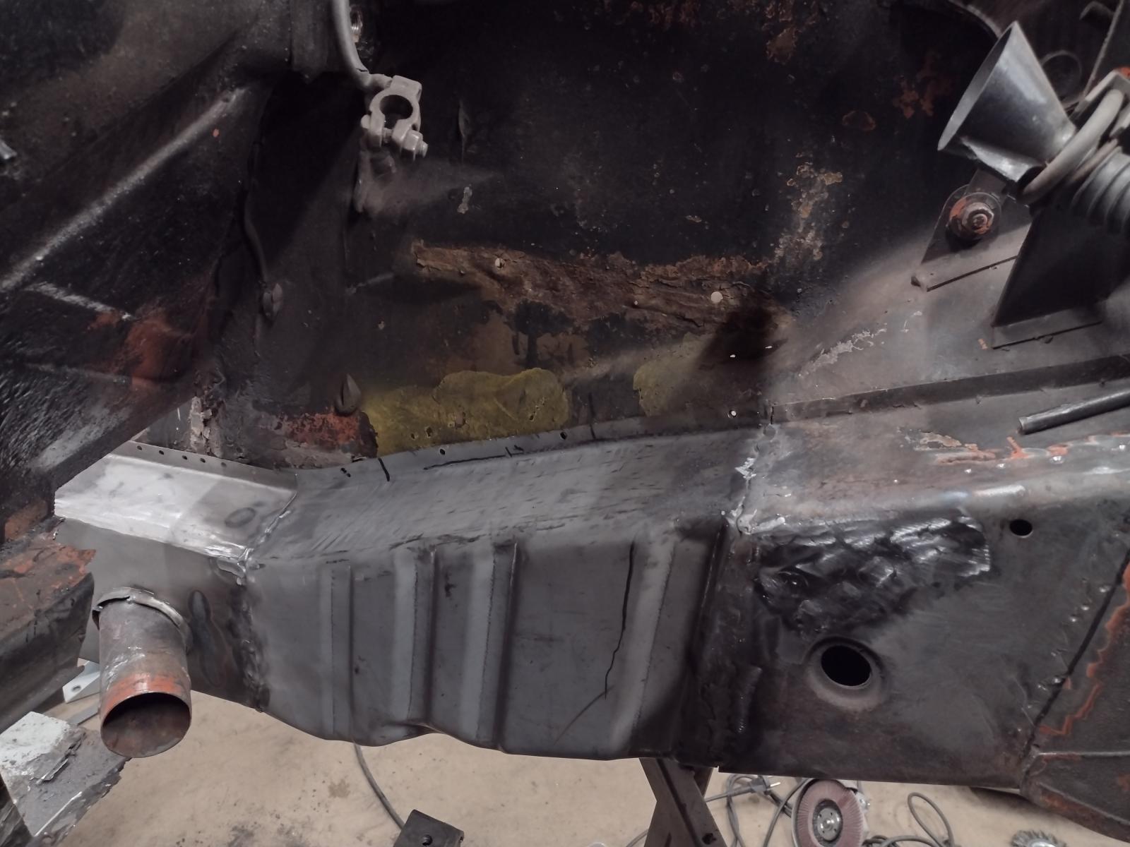
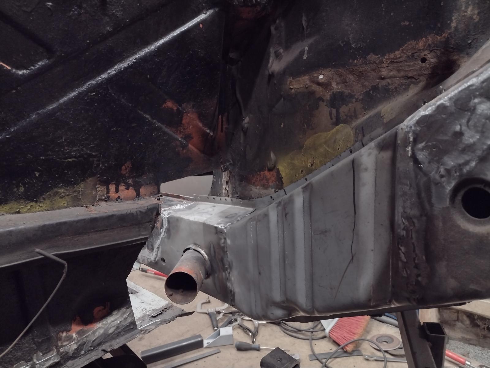
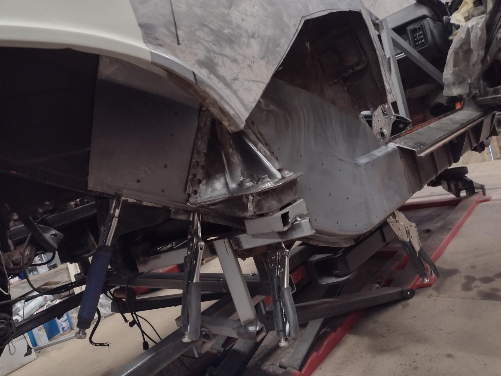
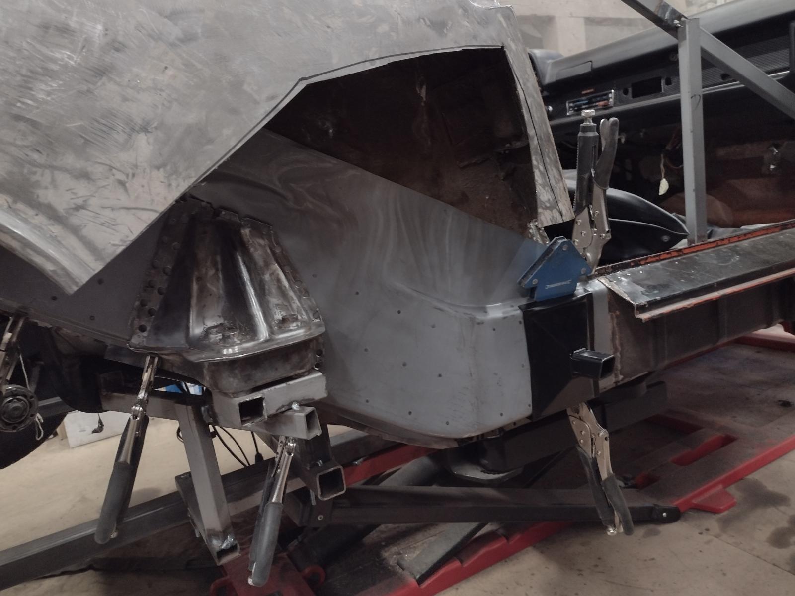
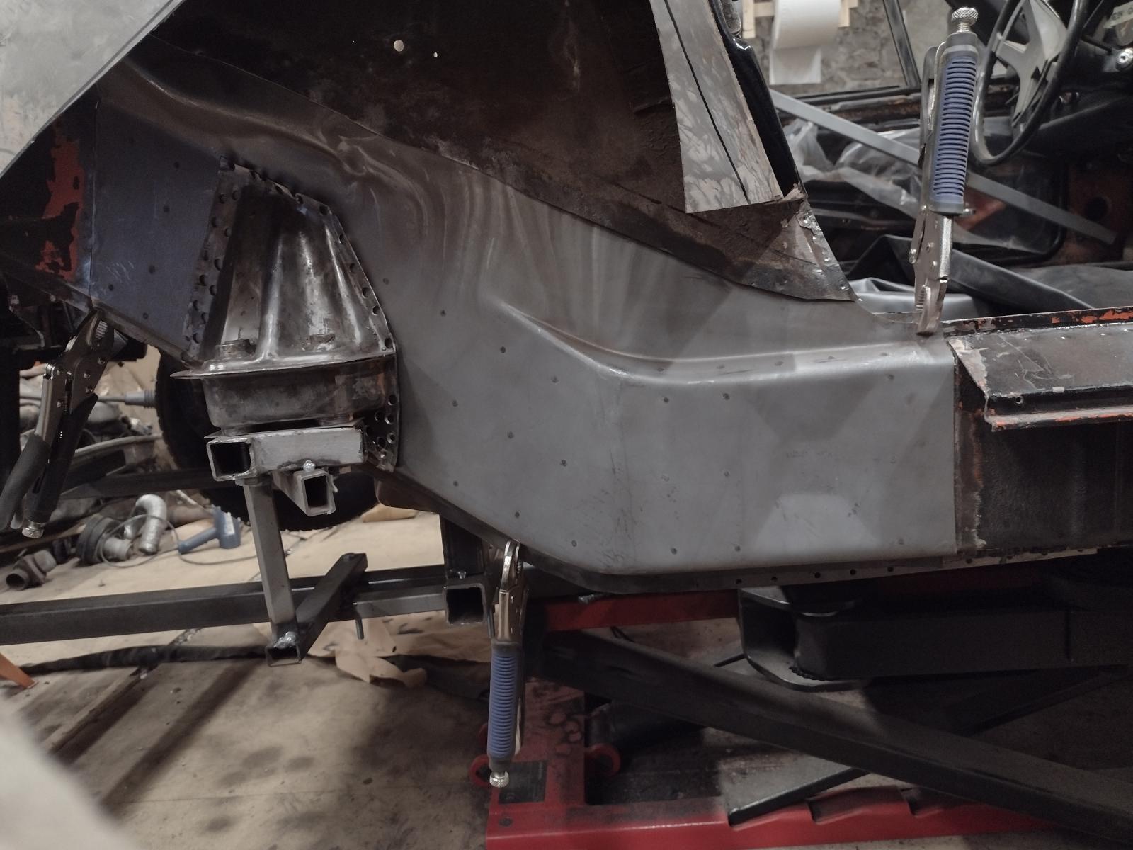
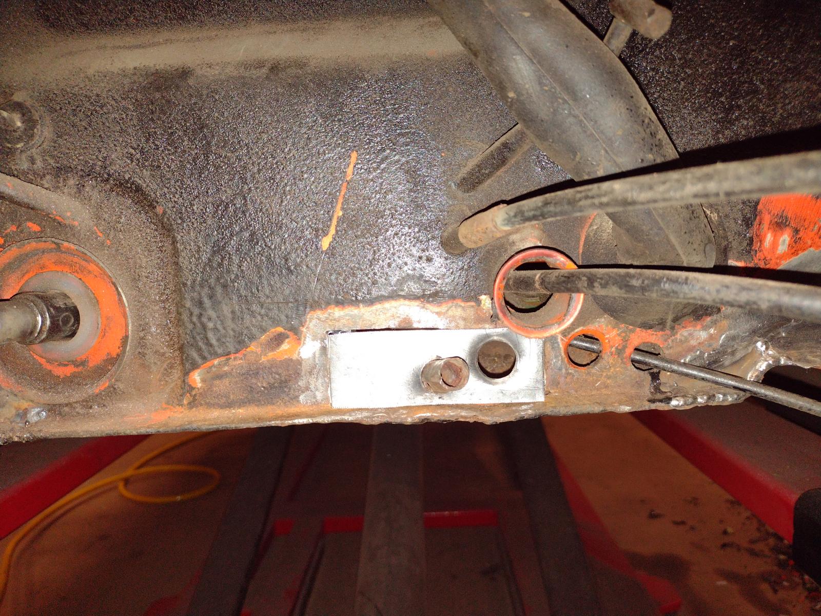
I made a lot of trial mounting, checking with all the elements,..Like here:
and now I am ready to weld it. I will weld it everywhere but to the wheel-well/outer long, to gain back some stability, then change the wheel well/outer long with the replacement part I already bought and I think it will be ok.
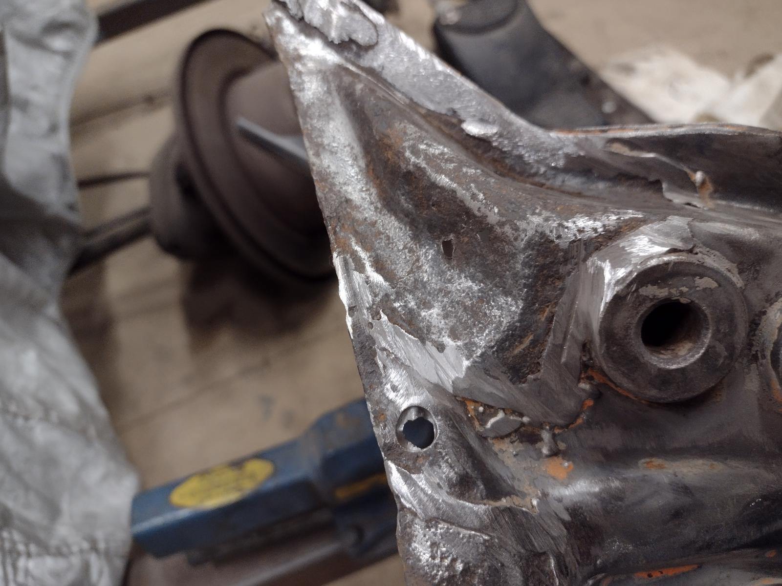
I ordered a new inner suspension console, but made the adjustment with the (rusted through) original one for the time being. One last check with the new one will take place before welding. I was happy to see everything going right back in with my jig and measurement being ok
I am searching for a replacement outer suspension console, hope to find one or I will have to repair mine, which might be hard..
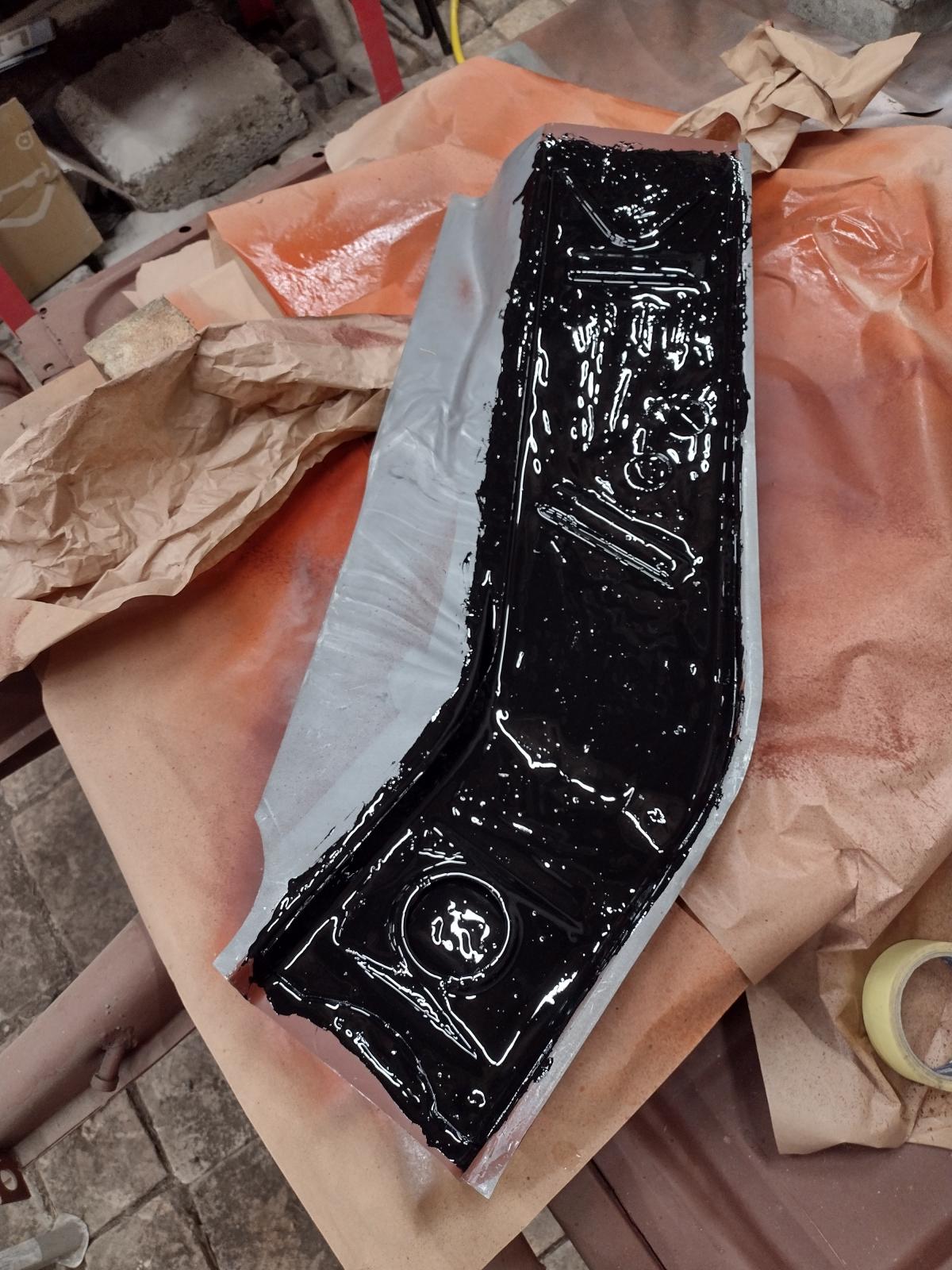
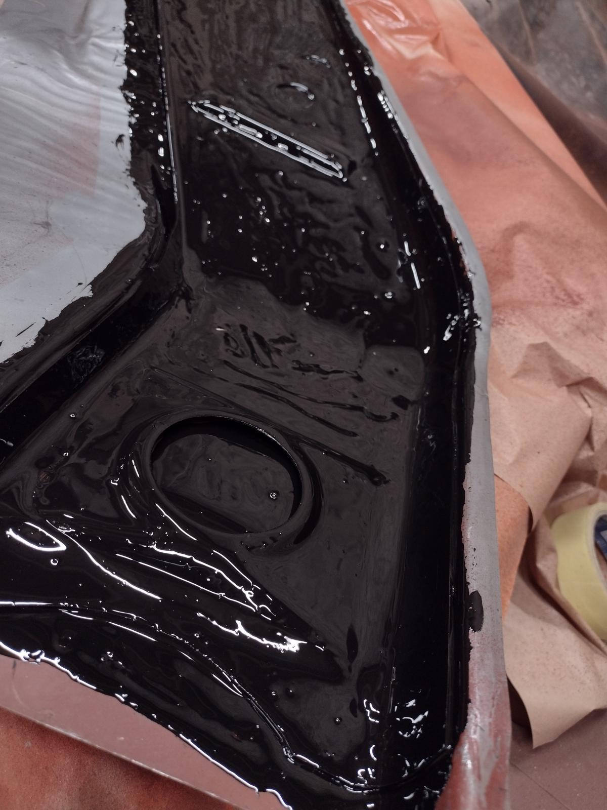
Last pictures, preparation for future welding done with welding primer where it will be welded in the future and rust protection paint everywhere else :
Bests
Antoine
@Superhawk996 : you're right, no possible heating, so it is currently 0°C in the shop
but motivation helps against the cold temperatures ! (And I bring home parts for example to paint).Next update!
I welded the repair part on the engine mount, now it's ready to be put back on
Then I started the adjustment on the inner long. First I put a lot of thoughts on were to make the connection and here was the best place I think, so let's cut:
And adjust:
I made a lot of trial mounting, checking with all the elements,..Like here:
and now I am ready to weld it. I will weld it everywhere but to the wheel-well/outer long, to gain back some stability, then change the wheel well/outer long with the replacement part I already bought and I think it will be ok.
I ordered a new inner suspension console, but made the adjustment with the (rusted through) original one for the time being. One last check with the new one will take place before welding. I was happy to see everything going right back in with my jig and measurement being ok
I am searching for a replacement outer suspension console, hope to find one or I will have to repair mine, which might be hard..
Last pictures, preparation for future welding done with welding primer where it will be welded in the future and rust protection paint everywhere else :
Bests
Antoine
Looks good. On the bright side the metal is less likely to warp due to 0C----32F when welding....
Matt
Matt
QUOTE(mate914 @ Dec 10 2021, 11:34 AM) 
Looks good. On the bright side the metal is less likely to warp due to 0C----32F when welding....
Matt
I love this positive way of thinking
Antoine
i know who to fly out to australia to fix 914s.
nice work.
i forgot to ask you, do you know where your car was sold new. which state?
keep at it.
nice work.
i forgot to ask you, do you know where your car was sold new. which state?
keep at it.
Thanks a lot for the nice words !!
I sadly do not know anything about its life in the US, the first documents I have are from its life in the UK.. and nothing in the VIN List before me
Antoine
I sadly do not know anything about its life in the US, the first documents I have are from its life in the UK.. and nothing in the VIN List before me
Antoine
Again a couple hours of work on the 914 this week!
First I received a small order:
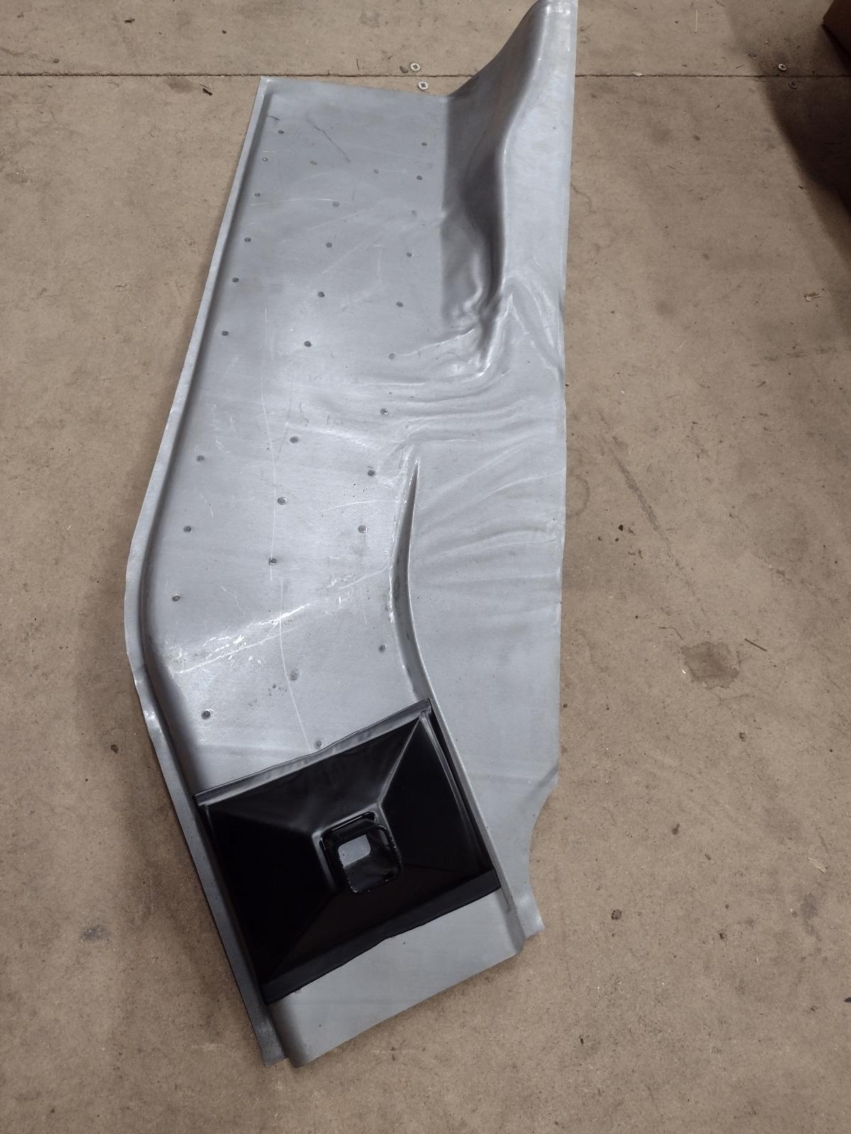
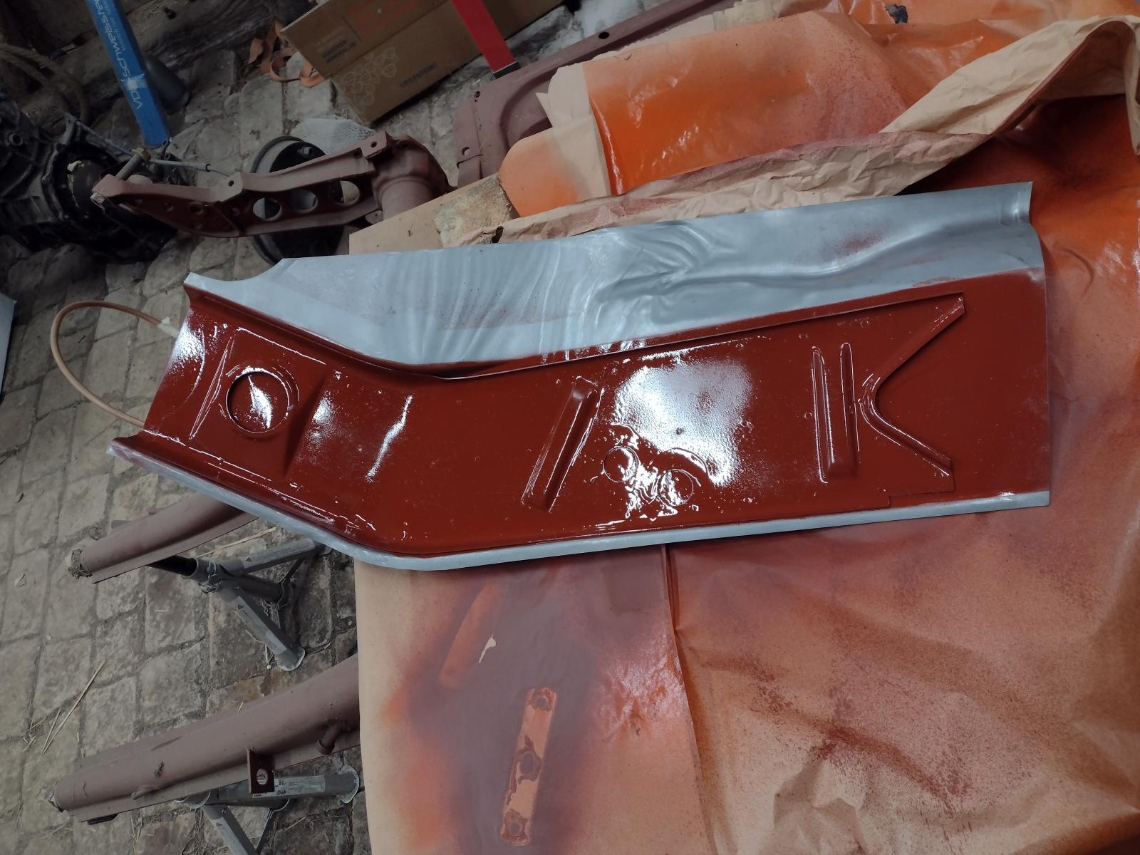
This suspension console looks a bit better :
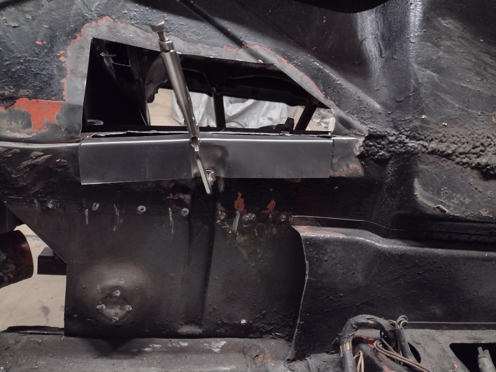
Then it was time for one last adjustment, check..and to get the welder out!
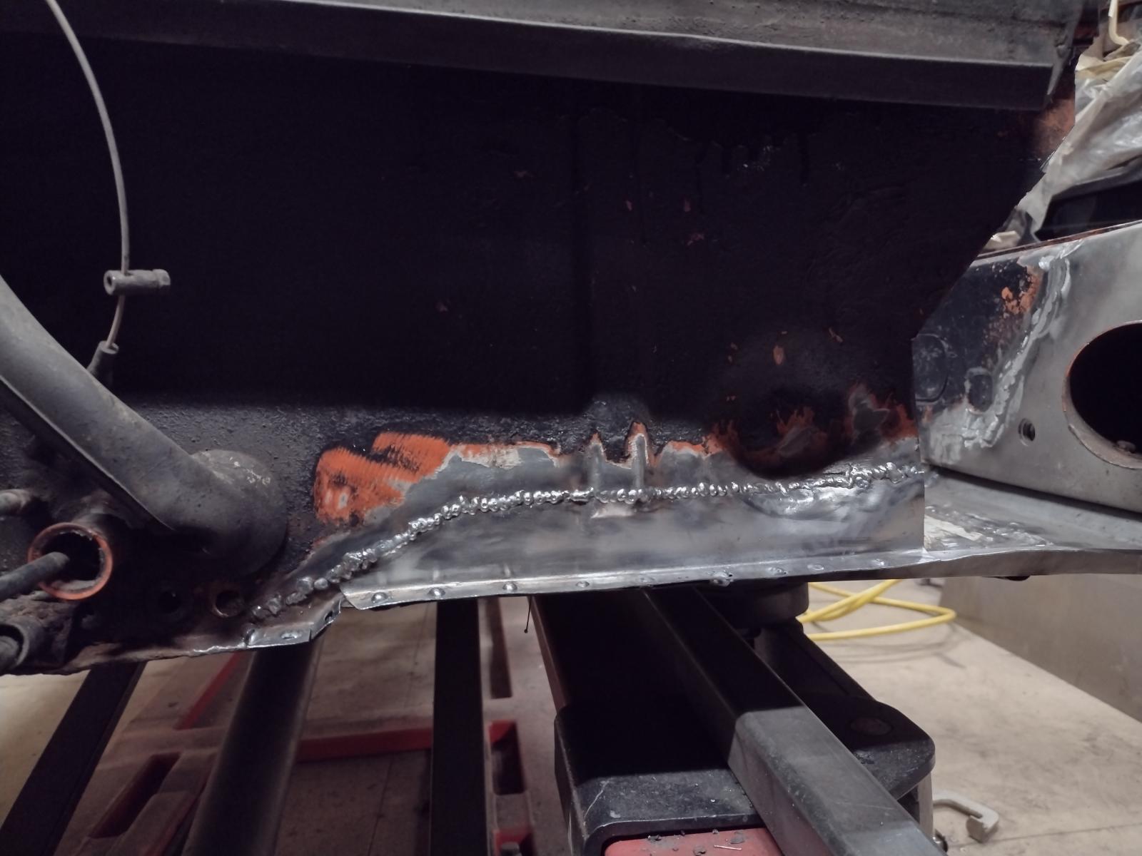
Couple of welding points:
One last check:
And everything is welded:
I did not grind so much to make sure no material thickness is removed. I will be planishing the weld and metal finishing it a bit more when the outer wheel-well/long reinforcement will be out. And then that will go on:
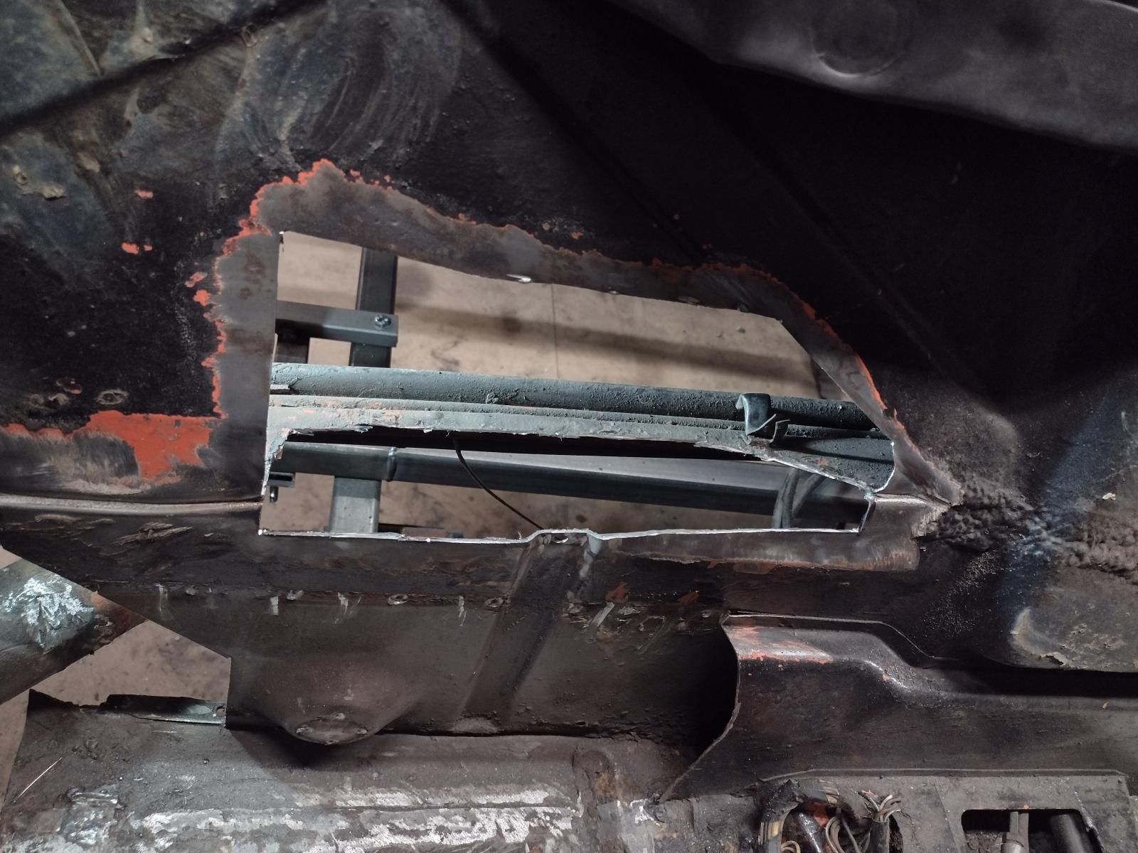
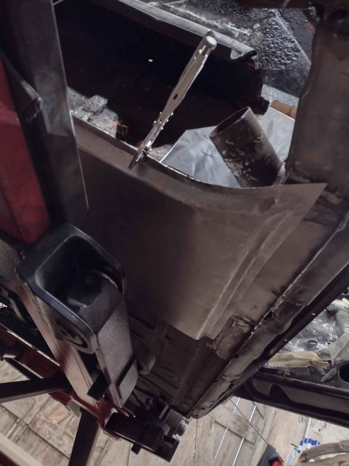
But before that I will weld back the engine mount next week, and also the inner suspension console. For that one I need your help/advice!
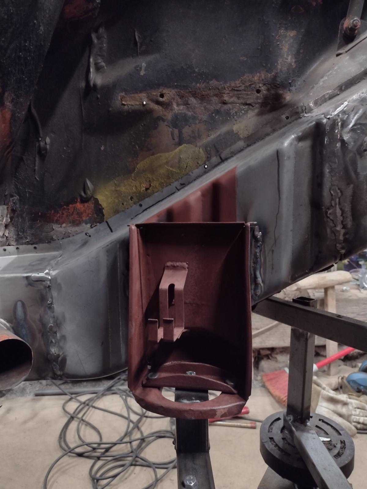
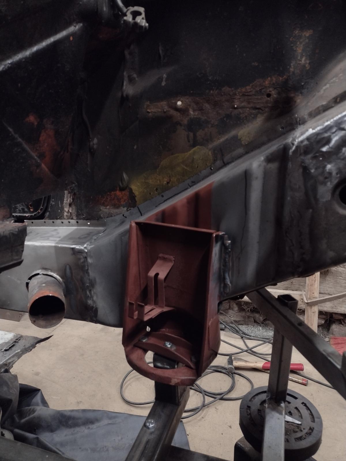
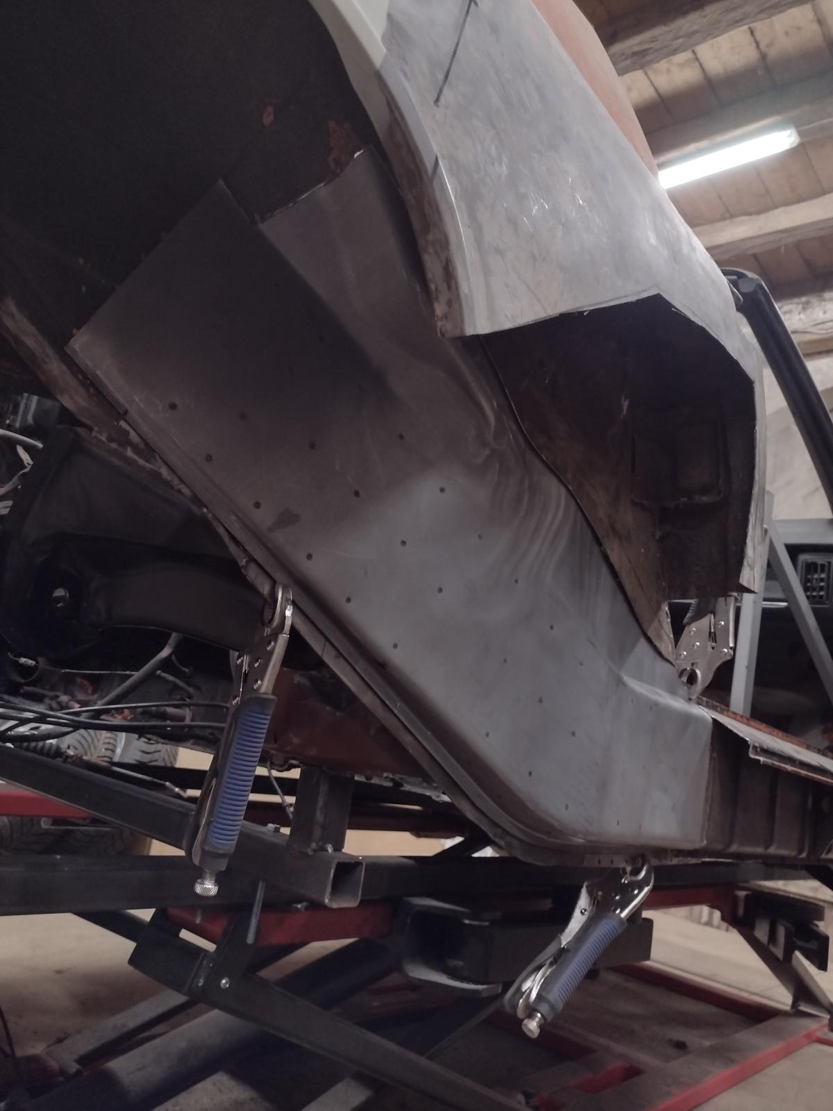
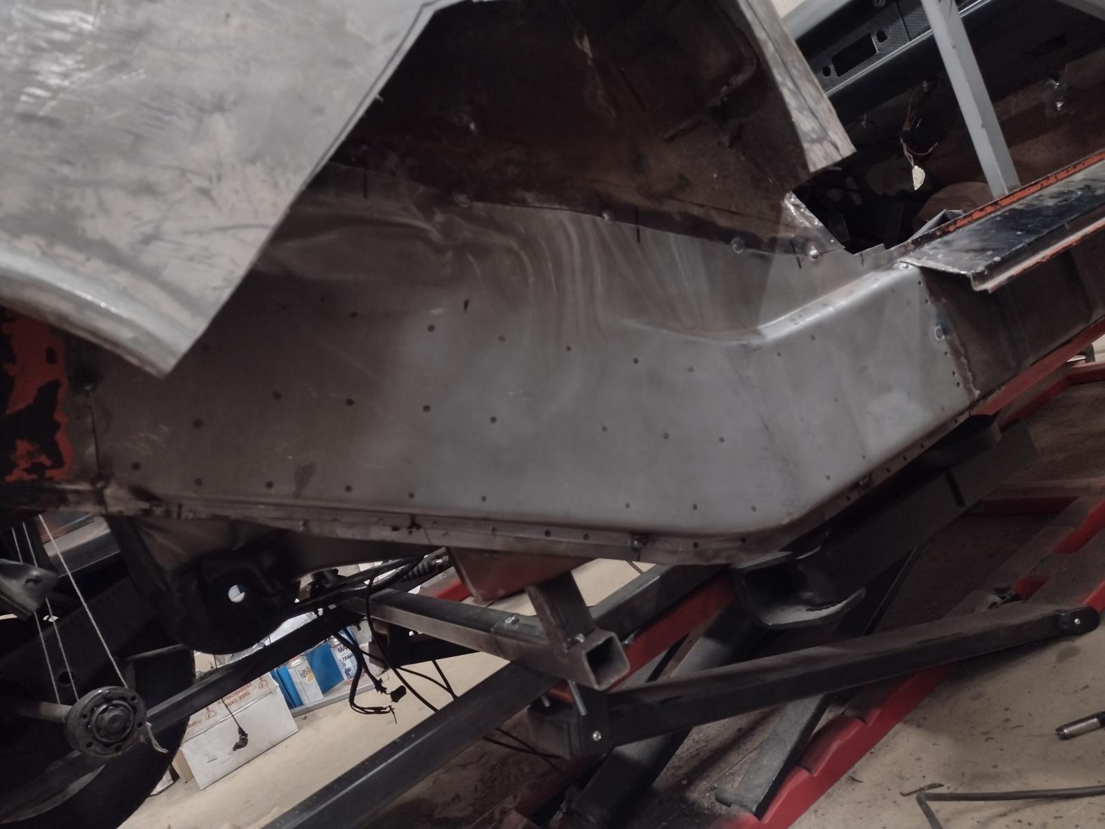
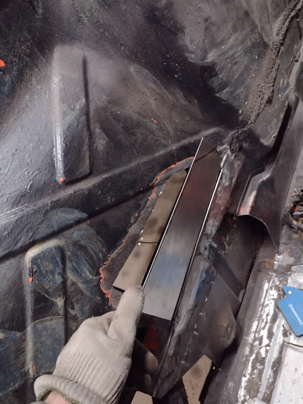
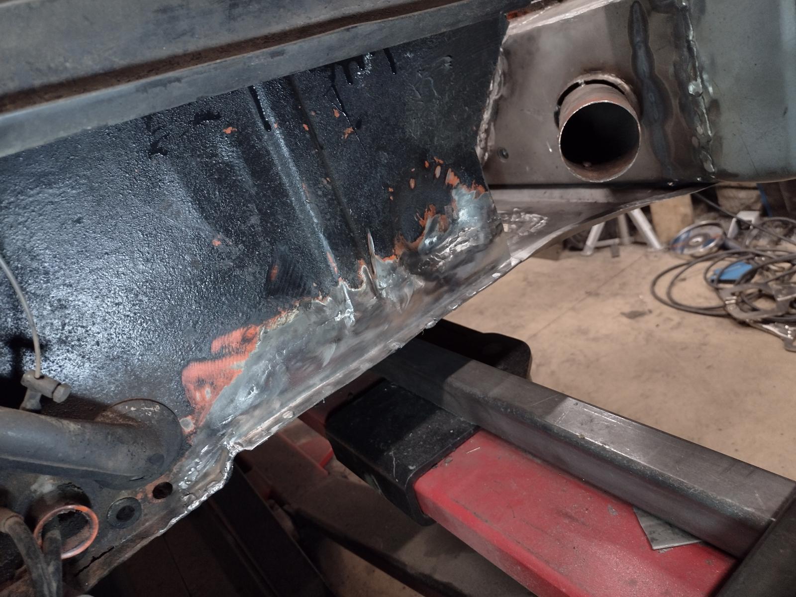
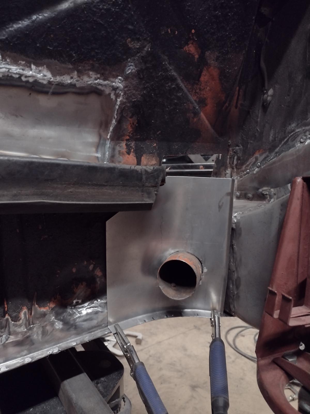
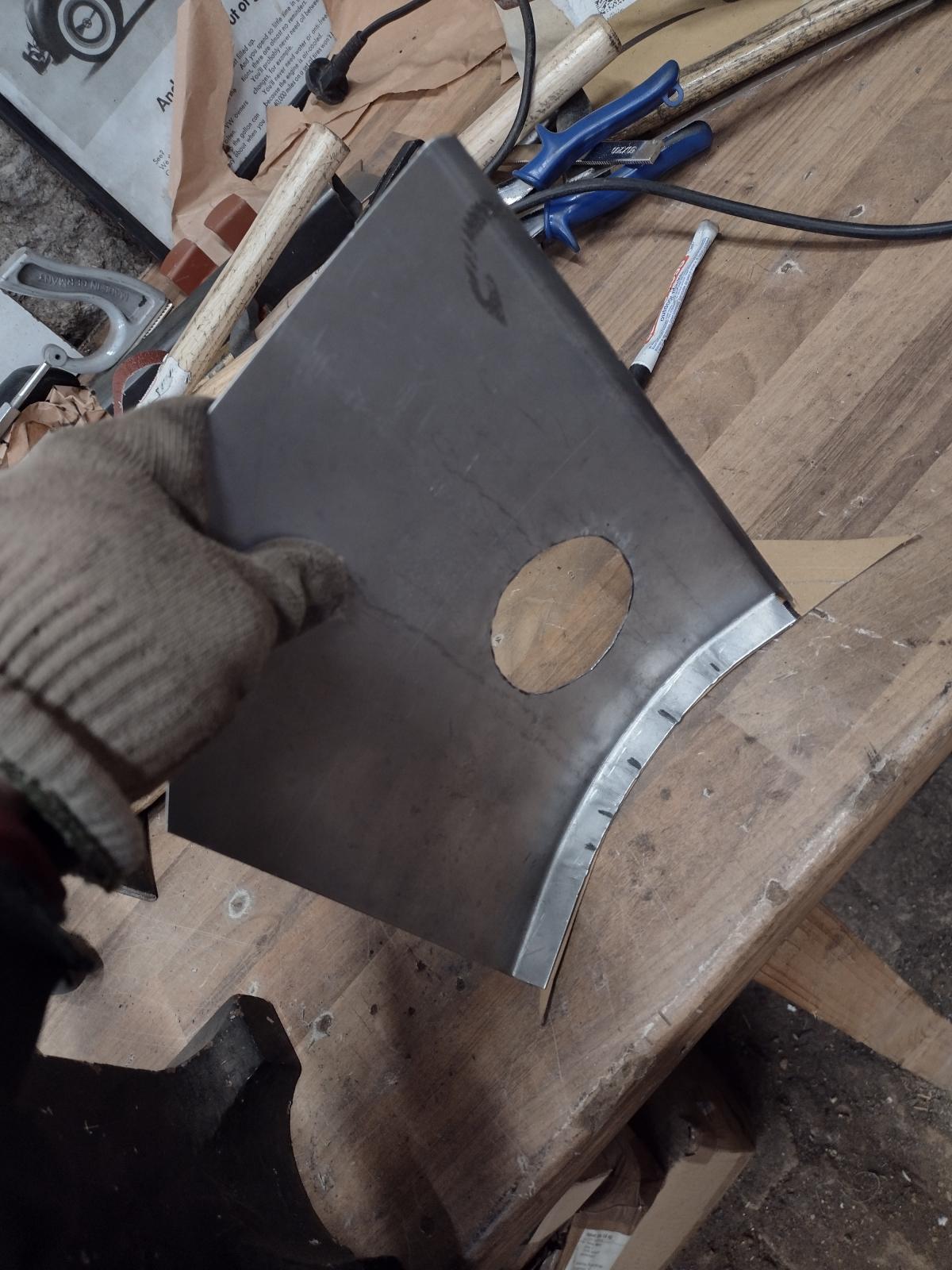
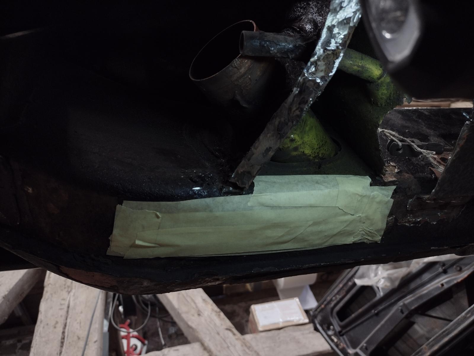
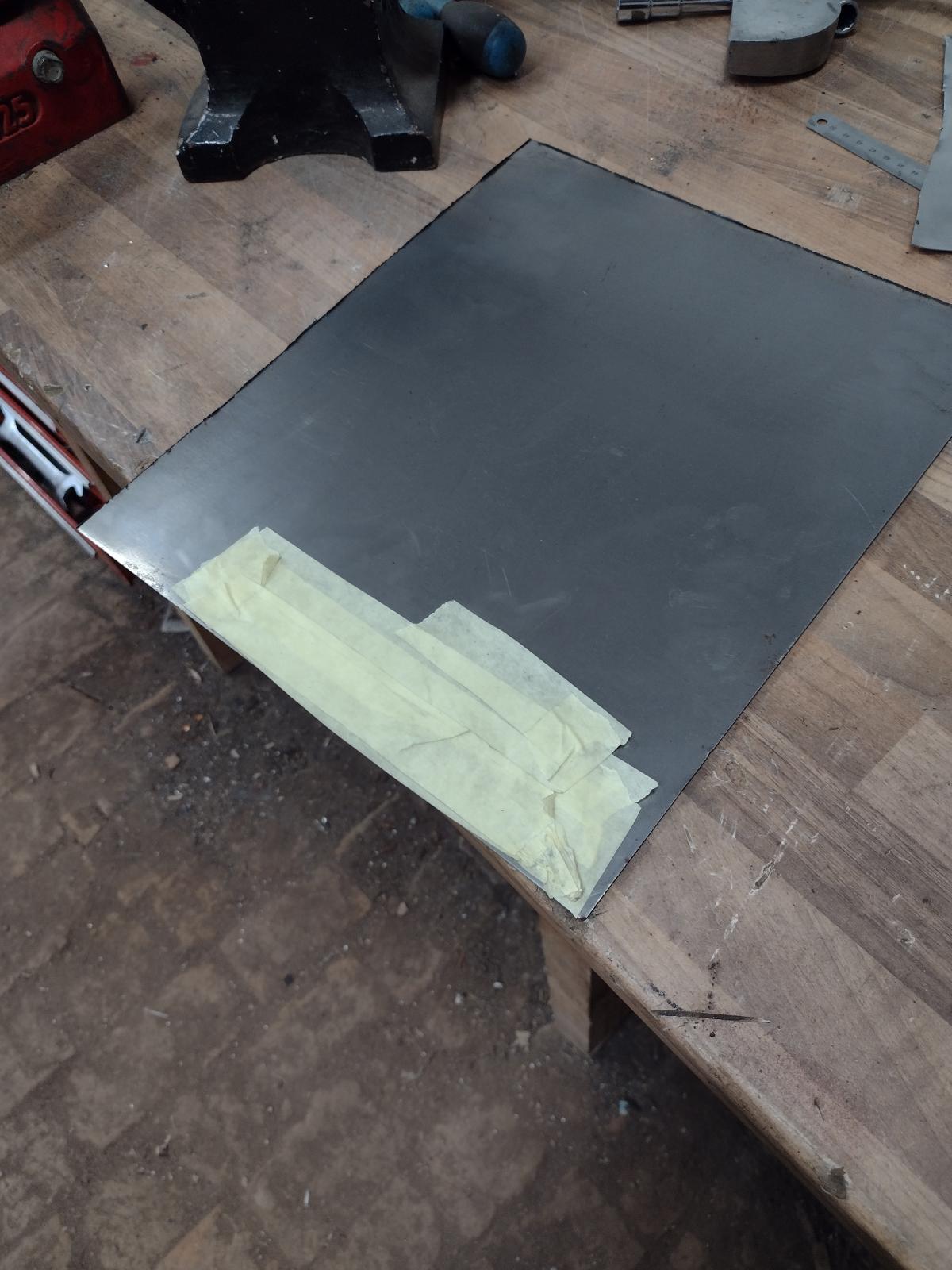
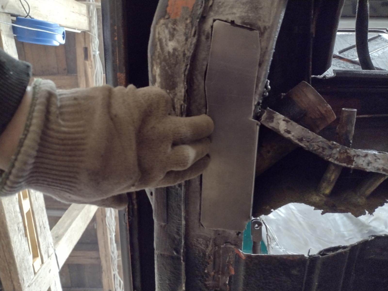
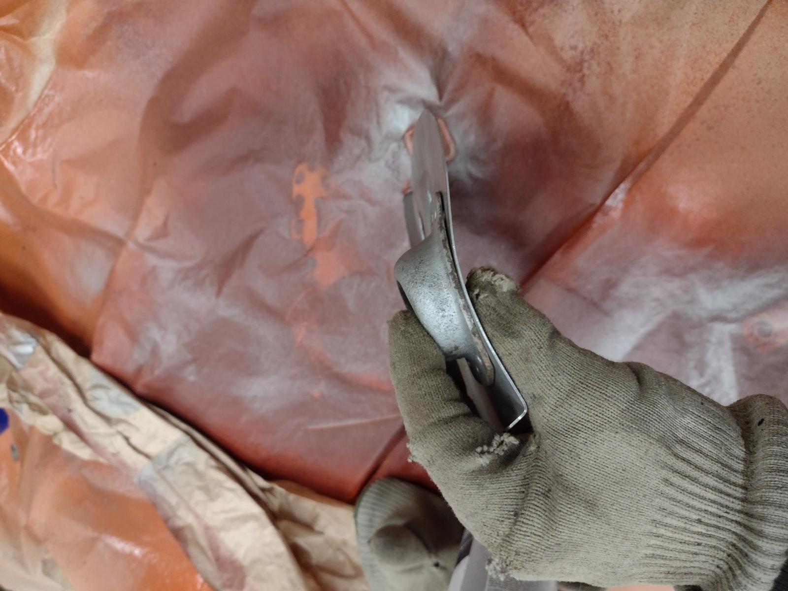
The new replacement part has a long bottom part that goes further than the lip between outer and inner long. That is the length:
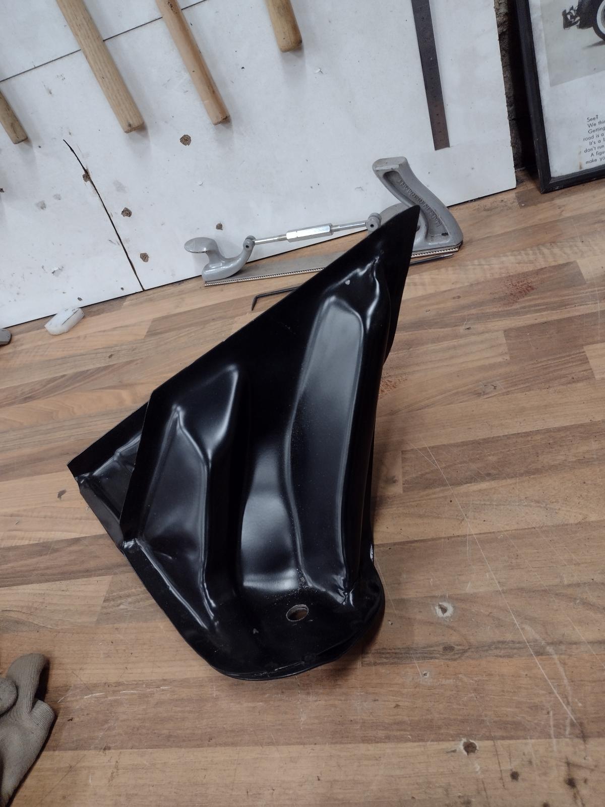
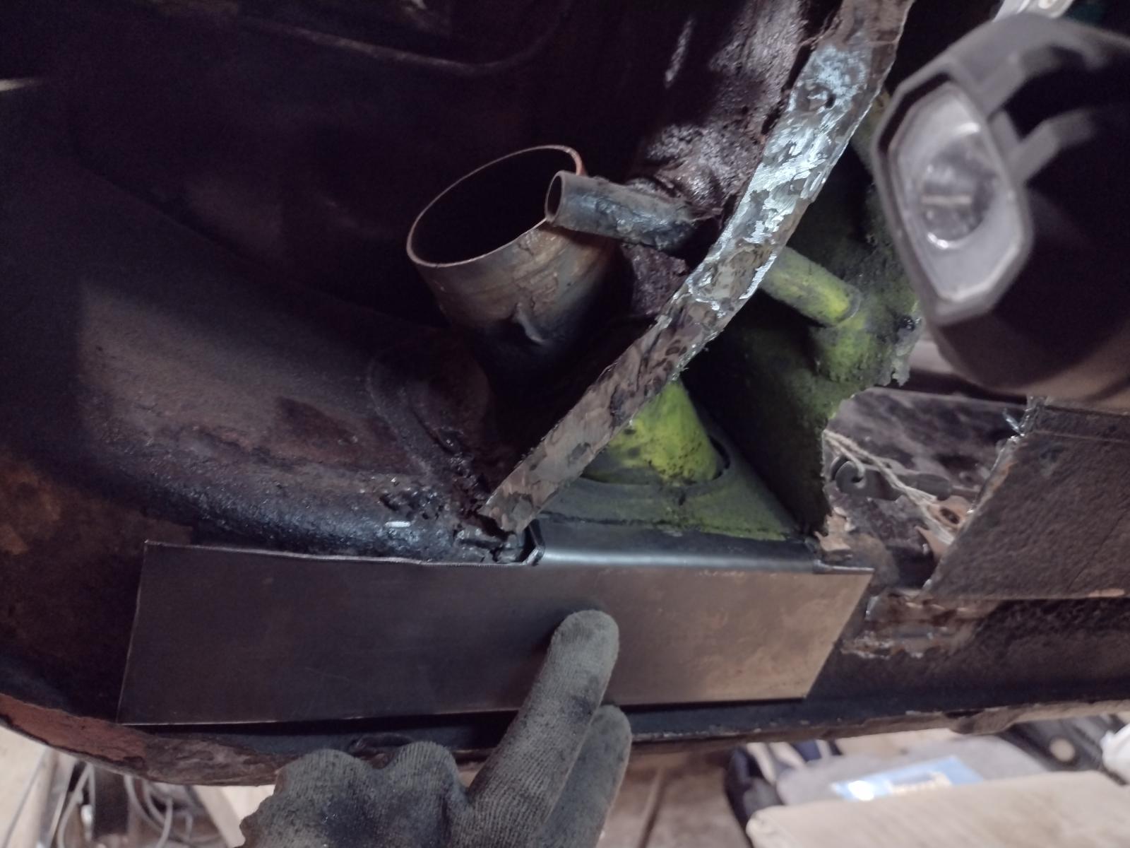
And the lip is approximatively where my finger is:
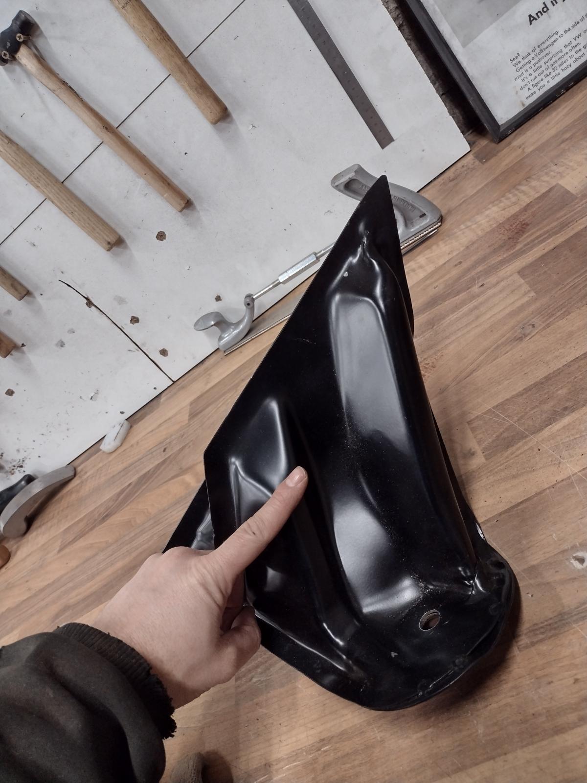
Should I remove the lip there and the suspension console goes further on the outside connecting with the outer suspension console or it has to be cut to join the outer console suspension exactly where the lip is ? That is a really important information to me, please tell me if my question is not clear!
Thanks
Antoine
First I received a small order:
This suspension console looks a bit better :
Then it was time for one last adjustment, check..and to get the welder out!
Couple of welding points:
One last check:
And everything is welded:
I did not grind so much to make sure no material thickness is removed. I will be planishing the weld and metal finishing it a bit more when the outer wheel-well/long reinforcement will be out. And then that will go on:
But before that I will weld back the engine mount next week, and also the inner suspension console. For that one I need your help/advice!
The new replacement part has a long bottom part that goes further than the lip between outer and inner long. That is the length:
And the lip is approximatively where my finger is:
Should I remove the lip there and the suspension console goes further on the outside connecting with the outer suspension console or it has to be cut to join the outer console suspension exactly where the lip is ? That is a really important information to me, please tell me if my question is not clear!
Thanks
Antoine
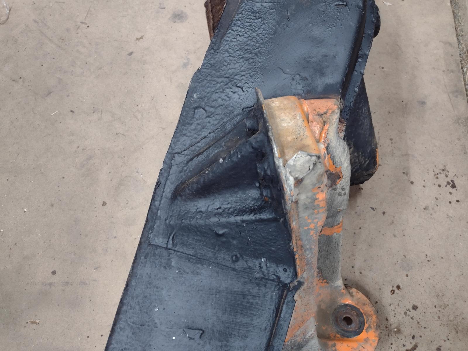
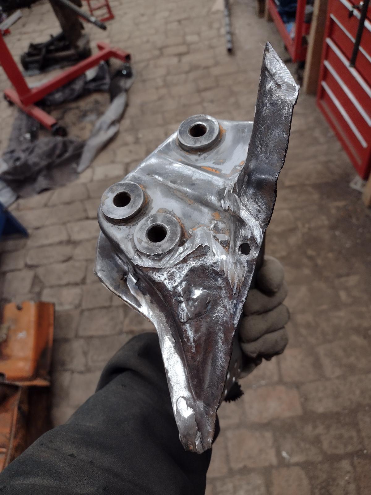
Hey Antione, looking great. I’m not quite sure what your asking, but here is my piece just prior to welding up. Not a new piece, was donated to me off a clean tub.
Back of piece.
Antione
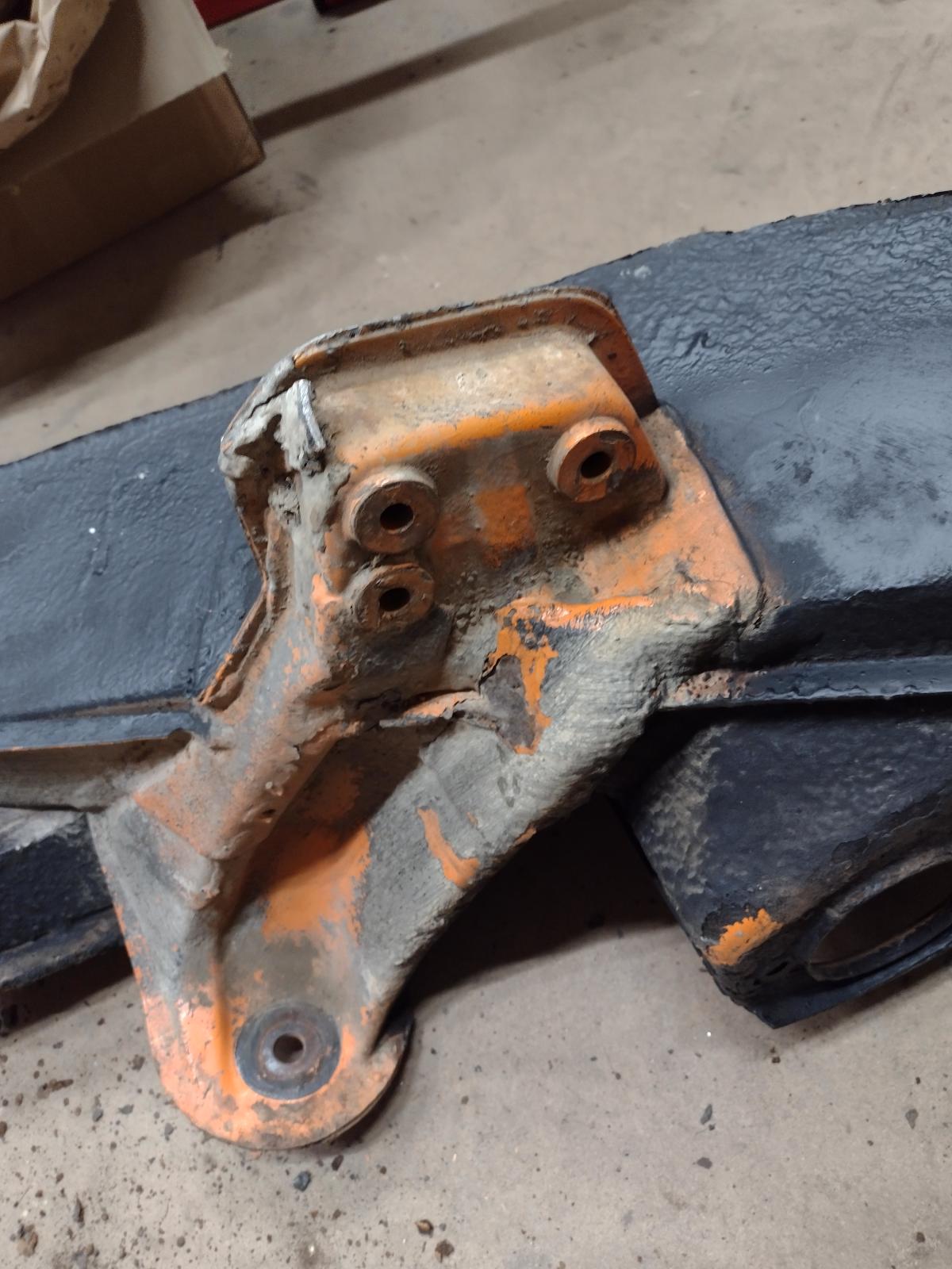
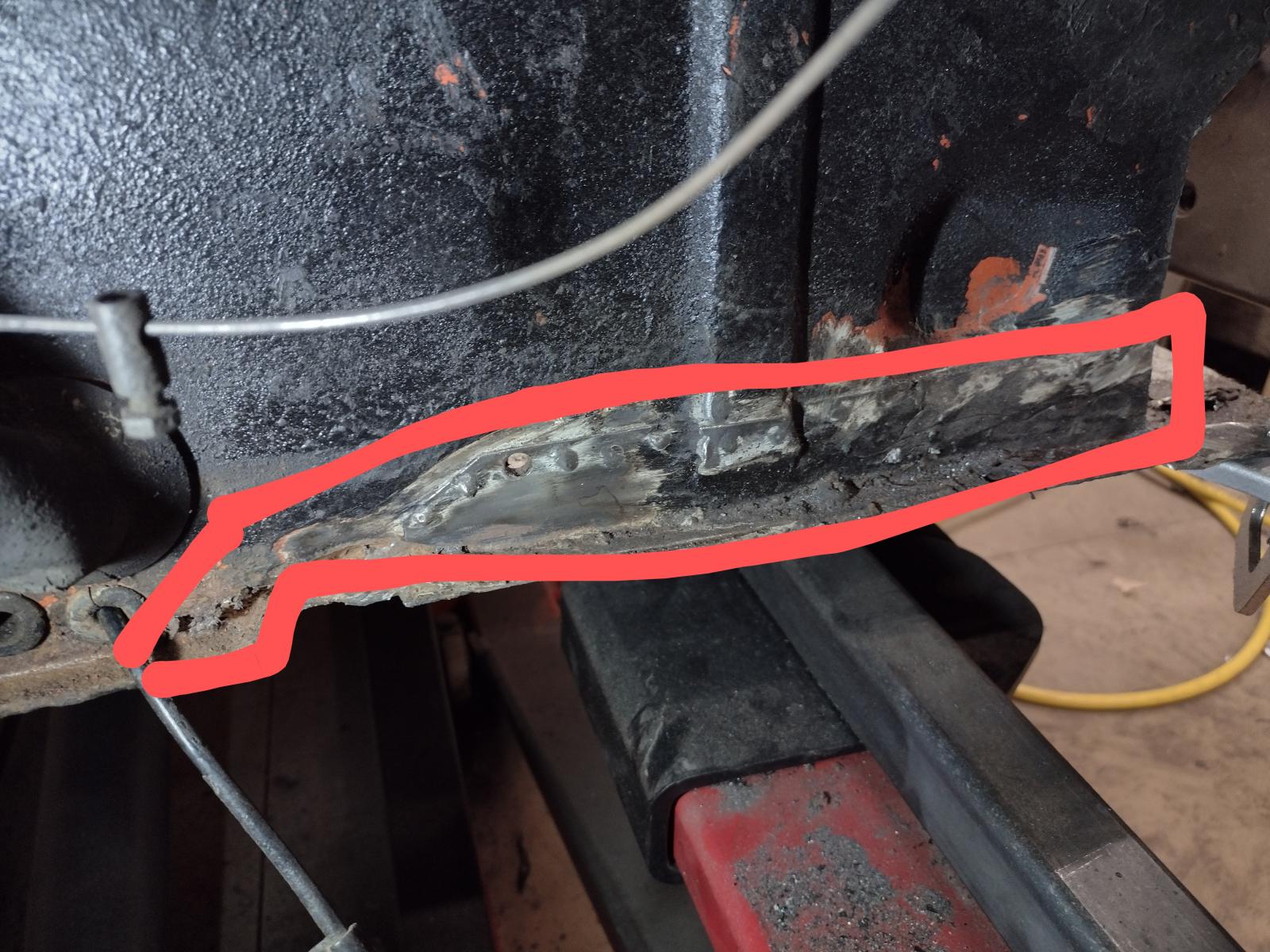
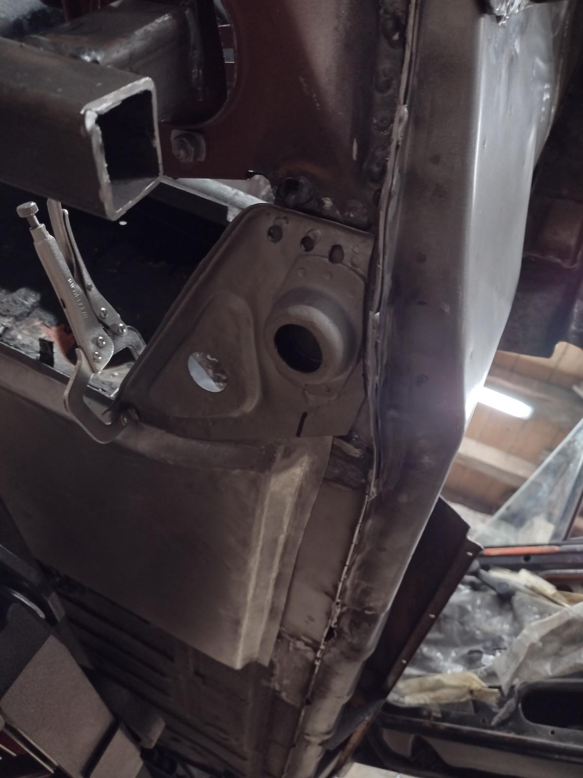
When I did a mock-up of my part the suspension console would not fit properly to the frame rail (longitudinal).
I had to trim a potion of it circled in yellow to allow the rest of the part to fit properly to the longitudial in the engine compartment.
You should not have to trim more than 4-5 mm off this stamping flange to get it to fit properly. You can see the shinny metal in the circle that I trimmed to make it fit.
Click to view attachment
I hope to get around to welding my suspension console inner into the proper postion during the upcoming Christmas holiday period.
For what it is worth I am not planning on welding my console into postion until I can get the other 3 corners of my suspension installed so that I can verify wheelbase, track width, and appropriate range of toe, and camber before I do final welding of that inner suspension console.
Thanks a lot guys for pour feedbacks! I tried to draw a bit the two versions I see :
1) trimming my part to fit on the inner long like that:
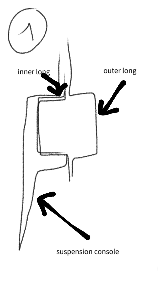
2)trimming the lip between inner and outer long to fit like that and join the outer console, like that:
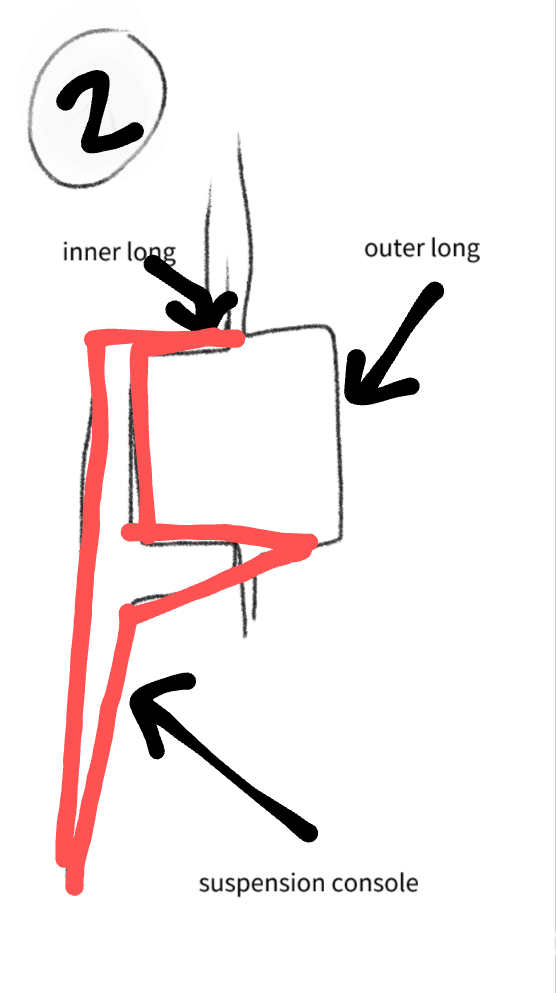
I think that number 1 is right but getting it confirmed would be good !
Thanks !
Antoine
1) trimming my part to fit on the inner long like that:
2)trimming the lip between inner and outer long to fit like that and join the outer console, like that:
I think that number 1 is right but getting it confirmed would be good !
Thanks !
Antoine
@TRS63
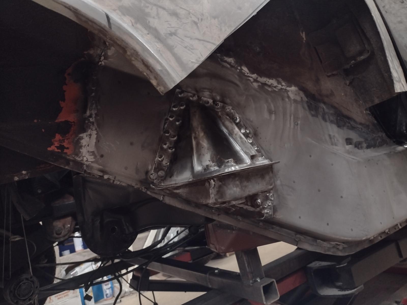
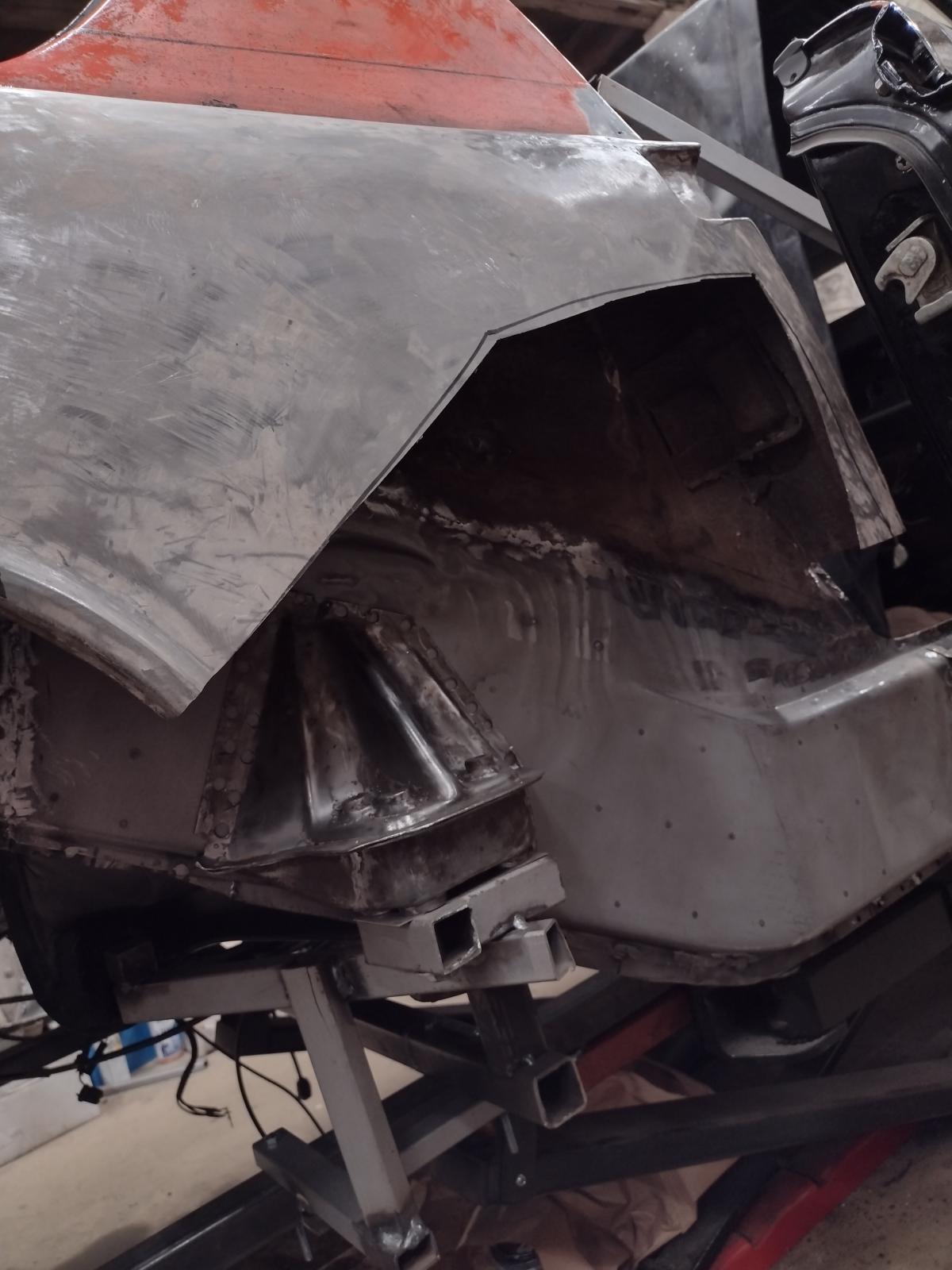
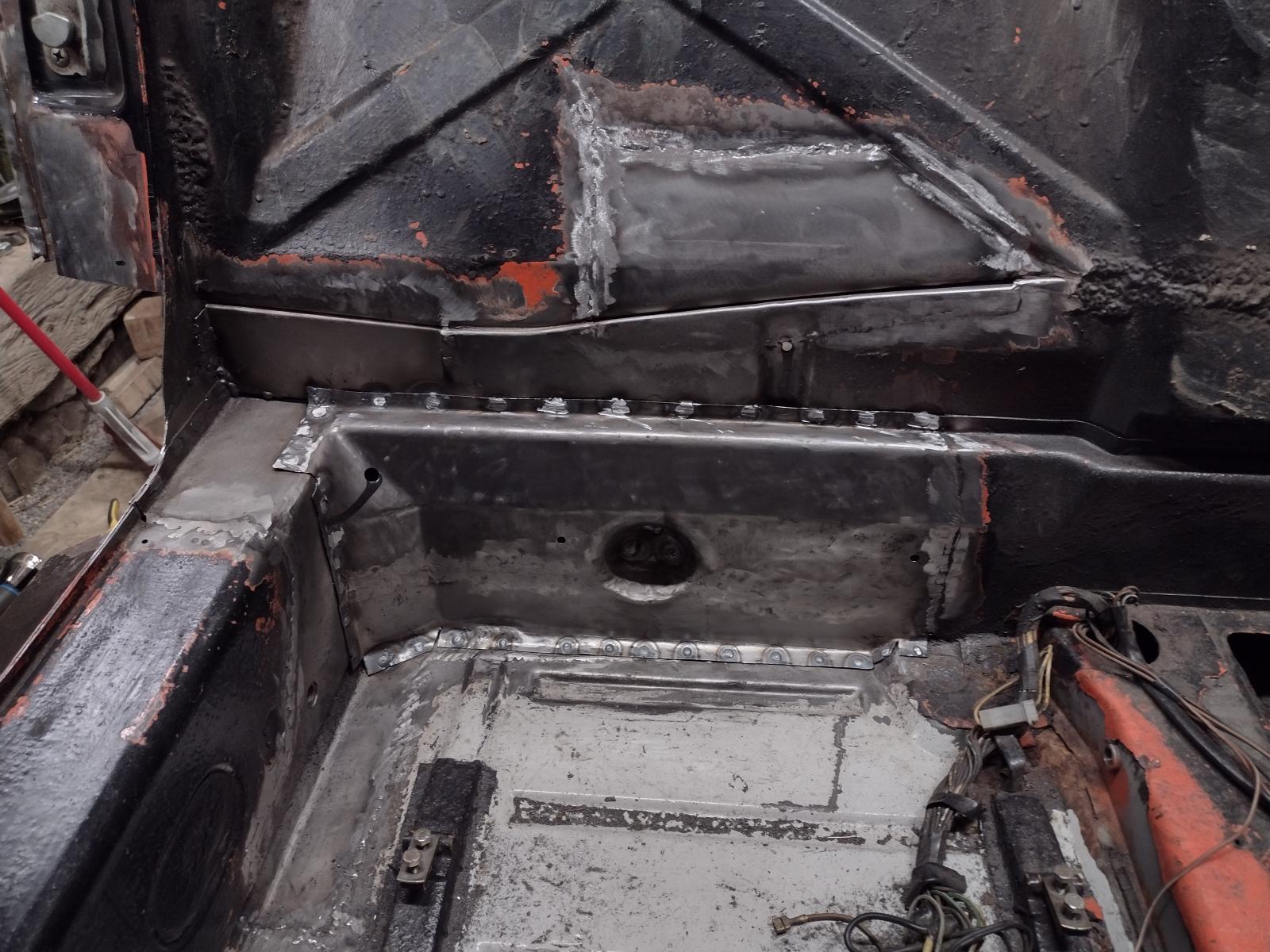
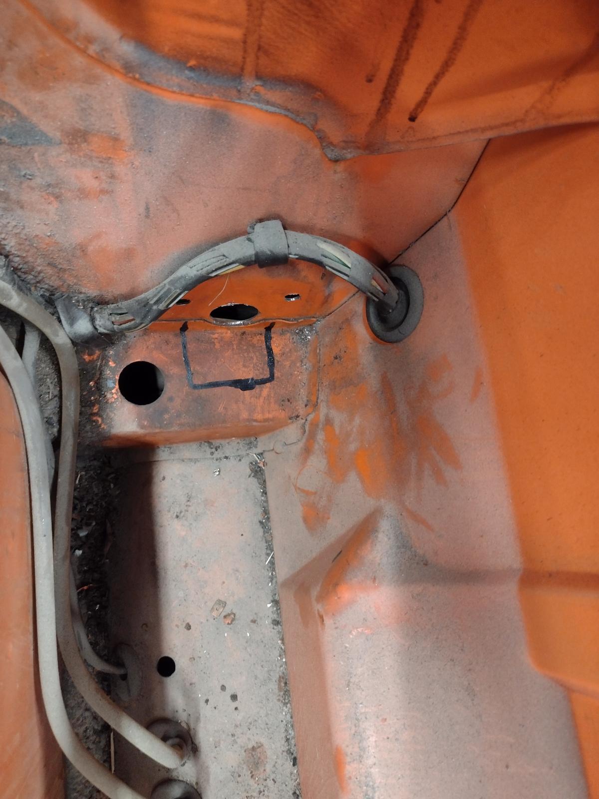
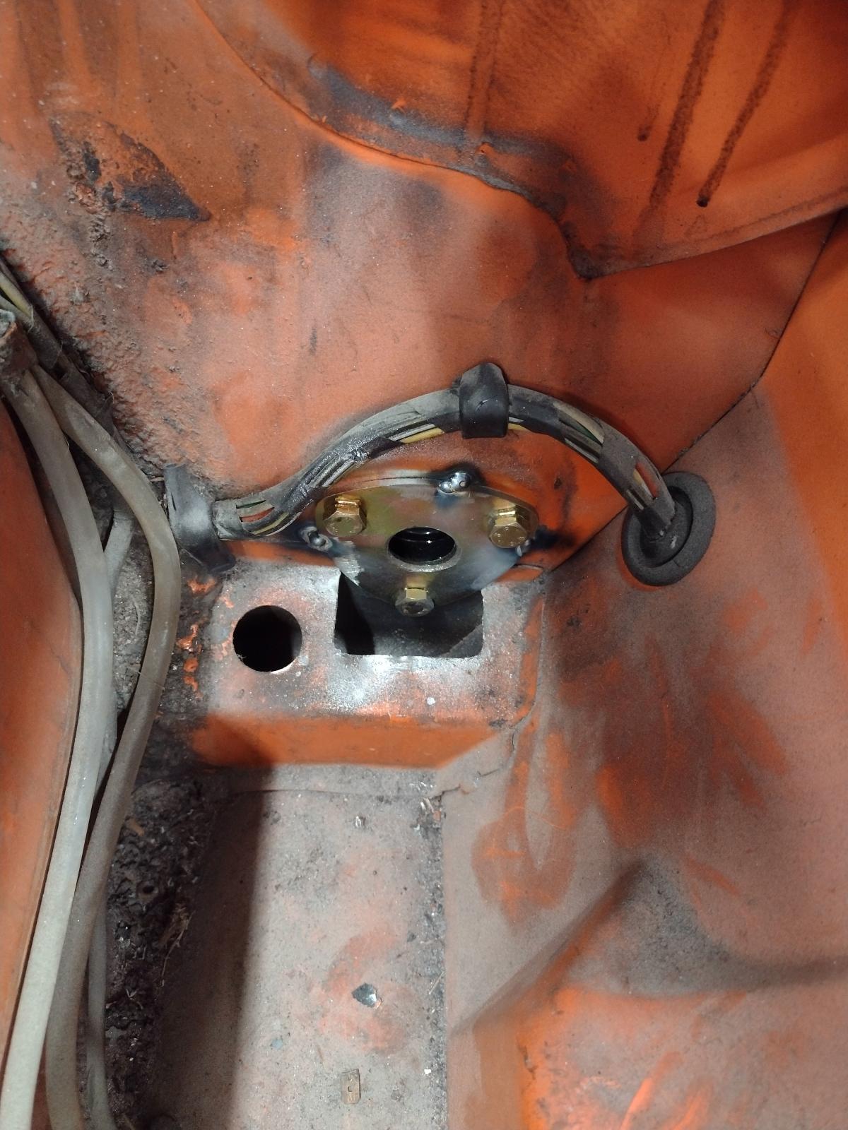
If you look at the other side, the OEM assembly left the downward standing flange of the inner longitudinal and the outer wheelhouse as shown in #1.
Click to view attachment
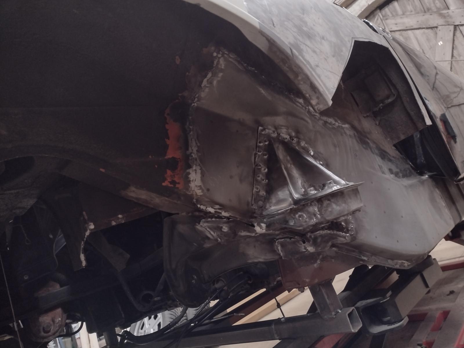
There are three "bow tie" type pieces (only two shown below) of heavier steel that serve to bridge over the downward facing flange and to tie the inner suspension console to the outer suspension console.
Click to view attachment
These heavy gauge "bow tie" pieces will provide far more structureal integrity to tie the inner suspension console to the outer suspension console than could be had by trimming the down standing flange and allowing the excess of the inner suspension console (maybe only about 1mm thick) to bridge the gap as would occur in #2.
Now the next question is where did I get these bow ties? @Mepstein donated them to me along with some other parts I ordered over a year ago. They are laser cut and about 3mm thick. They will need some OxyAcetylene heat to form them to fit. I don't know who made them. I know folks have been asking Restoration Design to make them but to date, no luck. I will be glad to do a paper tracing and send it to you via e-mail if you wish. Likewise, given your skill, you can create paper templates to the same effect off the car. That is what I was going to do before these pre-cut parts fell into my lap. PM me if need be.
If you look at the other side, the OEM assembly left the downward standing flange of the inner longitudinal and the outer wheelhouse as shown in #1.
Click to view attachment
There are three "bow tie" type pieces (only two shown below) of heavier steel that serve to bridge over the downward facing flange and to tie the inner suspension console to the outer suspension console.
Click to view attachment
These heavy gauge "bow tie" pieces will provide far more structureal integrity to tie the inner suspension console to the outer suspension console than could be had by trimming the down standing flange and allowing the excess of the inner suspension console (maybe only about 1mm thick) to bridge the gap as would occur in #2.
Now the next question is where did I get these bow ties? @Mepstein donated them to me along with some other parts I ordered over a year ago. They are laser cut and about 3mm thick. They will need some OxyAcetylene heat to form them to fit. I don't know who made them. I know folks have been asking Restoration Design to make them but to date, no luck. I will be glad to do a paper tracing and send it to you via e-mail if you wish. Likewise, given your skill, you can create paper templates to the same effect off the car. That is what I was going to do before these pre-cut parts fell into my lap. PM me if need be.
QUOTE(Superhawk996 @ Dec 18 2021, 10:03 AM)
If you look at the other side, the OEM assembly left the downward standing flange of the inner longitudinal and the outer wheelhouse as shown in #1.
Click to view attachment
There are three "bow tie" type pieces (only two shown below) of heavier steel that serve to bridge over the downward facing flange and to tie the inner suspension console to the outer suspension console.
Click to view attachment
These heavy gauge "bow tie" pieces will provide far more structureal integrity to tie the inner suspension console to the outer suspension console than could be had by trimming the down standing flange and allowing the excess of the inner suspension console (maybe only about 1mm thick) to bridge the gap as would occur in #2.
Now the next question is where did I get these bow ties? @Mepstein donated them to me along with some other parts I ordered over a year ago. They are laser cut and about 3mm thick. I don't know who made them. I know folks have been asking Restoration Design to make them but to date, no luck. I will be glad to do a paper tracing and send it to you via e-mail if you wish. Likewise, given your skill, you can create paper templates to the same effect off the car. That is what I was going to do before these pre-cut parts fell into my lap. PM me if need be.
They came from 914rubber. Cary had drawn up the templates for them.
QUOTE(mepstein @ Dec 18 2021, 10:10 AM)
They came from 914rubber. Cary had drawn up the templates for them.
What a terrible tragedy that Cary is no longer with the community. Apparently, his contribution lives on. That is awesome that 914Rubber makes them.
https://914rubber.com/trailing-arm-suspensi...t-set-by-cary-1
@Mepstein -- Thanks Mark - not only for the parts, but, for the information about where they came from that will help others.
Awesome informations, Thiam forum really is fantastic, thanks to all of you for the help !
I will check if I can measure them on the other side or by measuring, otherwise I will come back to you ! thanks a lot!
Antoine
I will check if I can measure them on the other side or by measuring, otherwise I will come back to you ! thanks a lot!
Antoine
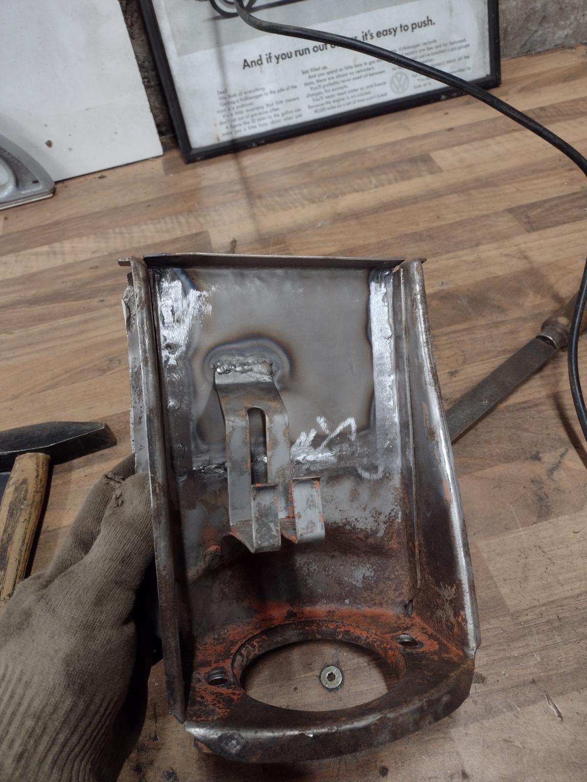
Antione, just for more info…here is what I was able to salvage when I did mine.
I removed and saved these “tie-ins” . Just to give you an idea of the shape. Phil explained pretty much spot on!
Carry on
I removed and saved these “tie-ins” . Just to give you an idea of the shape. Phil explained pretty much spot on!
Carry on
Looks good, thanks for those extra pictures. As my outer console is also rusted through, I bought a used section including one that is supposed to be in good conditions and these tie ins should also be there..hopefully I can save them or use them as a template  let's see when it shows up!
Antoine
let's see when it shows up!Antoine
Small update :
We have a welded in engine mount:
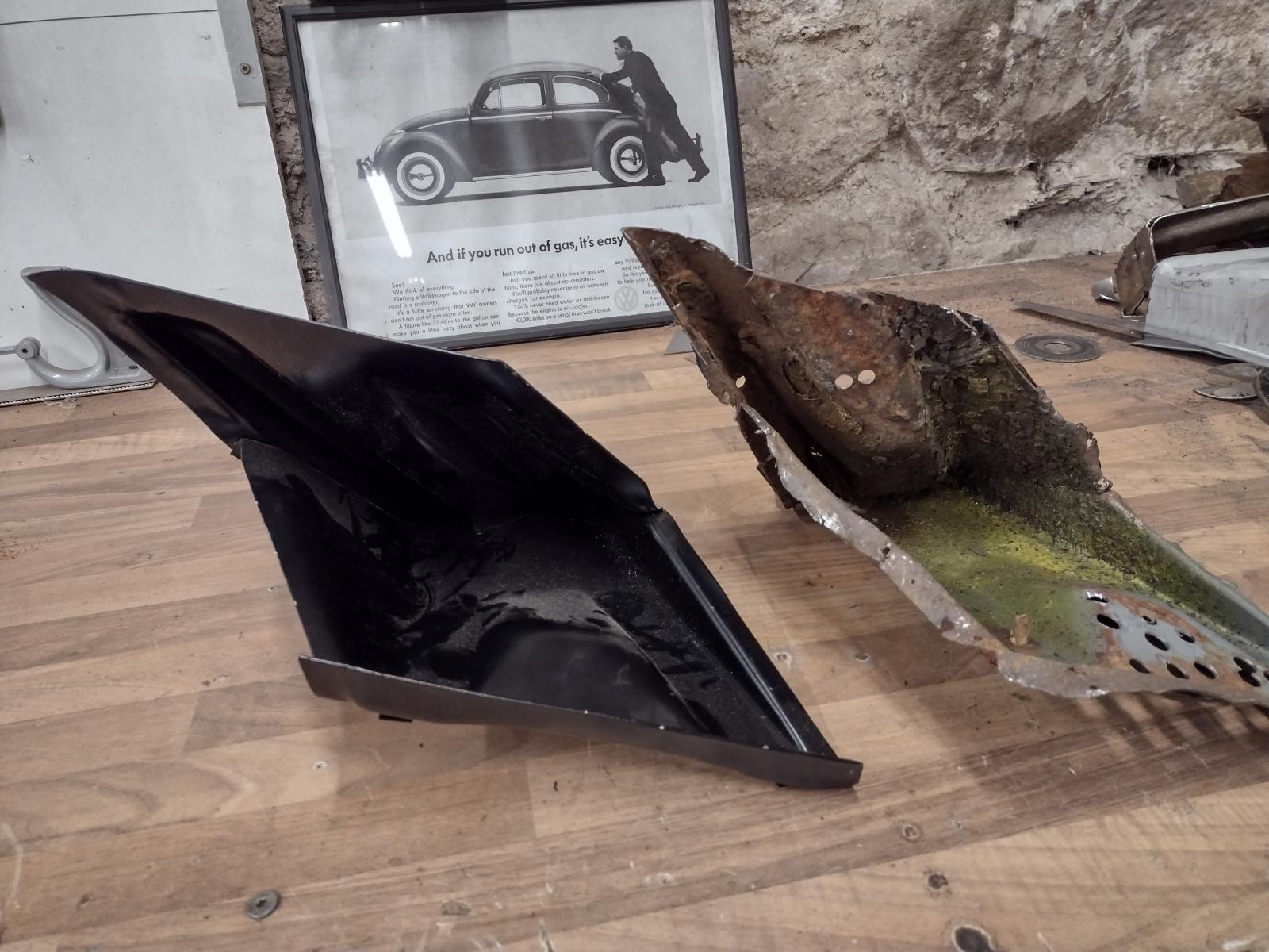
And I got a "new" outer suspension console..well just need to disassemble it :
Stay tuned, I hope to make some serious hours in the shop in January !
Antoine
We have a welded in engine mount:
And I got a "new" outer suspension console..well just need to disassemble it :
Stay tuned, I hope to make some serious hours in the shop in January !
Antoine
Good luck with taking the console apart. Looks good from the outside. Hopefully just as decent on the inside.
Coming along nicely.
Coming along nicely.
Thanks a lot Dion!
I managed to work some hours on it this week!
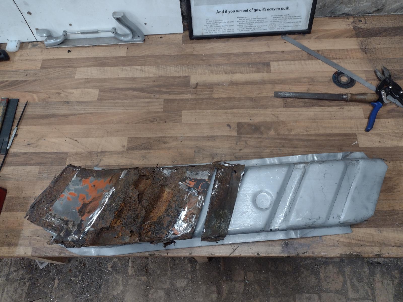
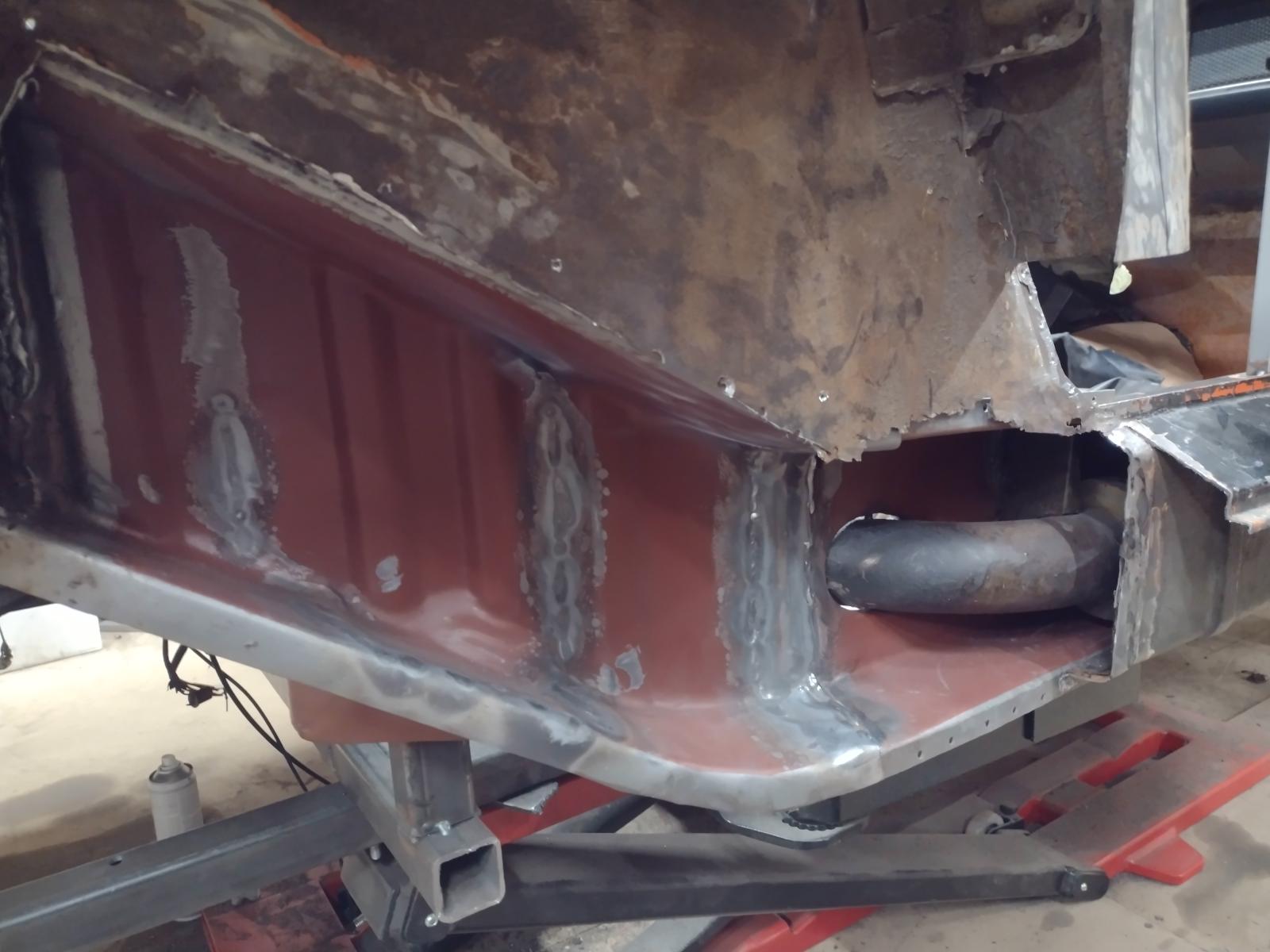
I disassemble my new to me outer suspension console and cleaned/blasted it :
The inside showed only some surface rust :
Except these small holes:
That I welded shut :
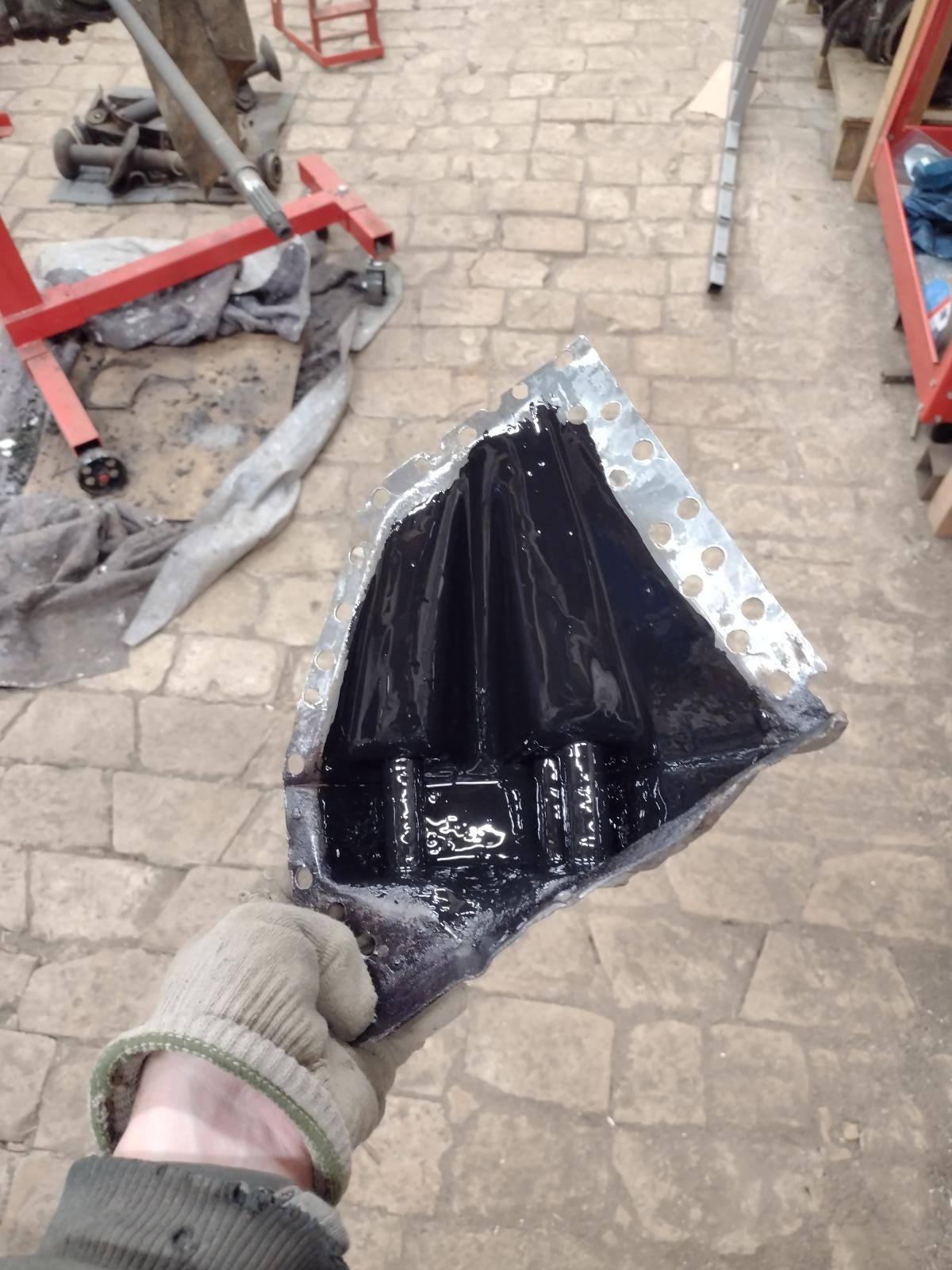
I then treated the inside with some rust protection :
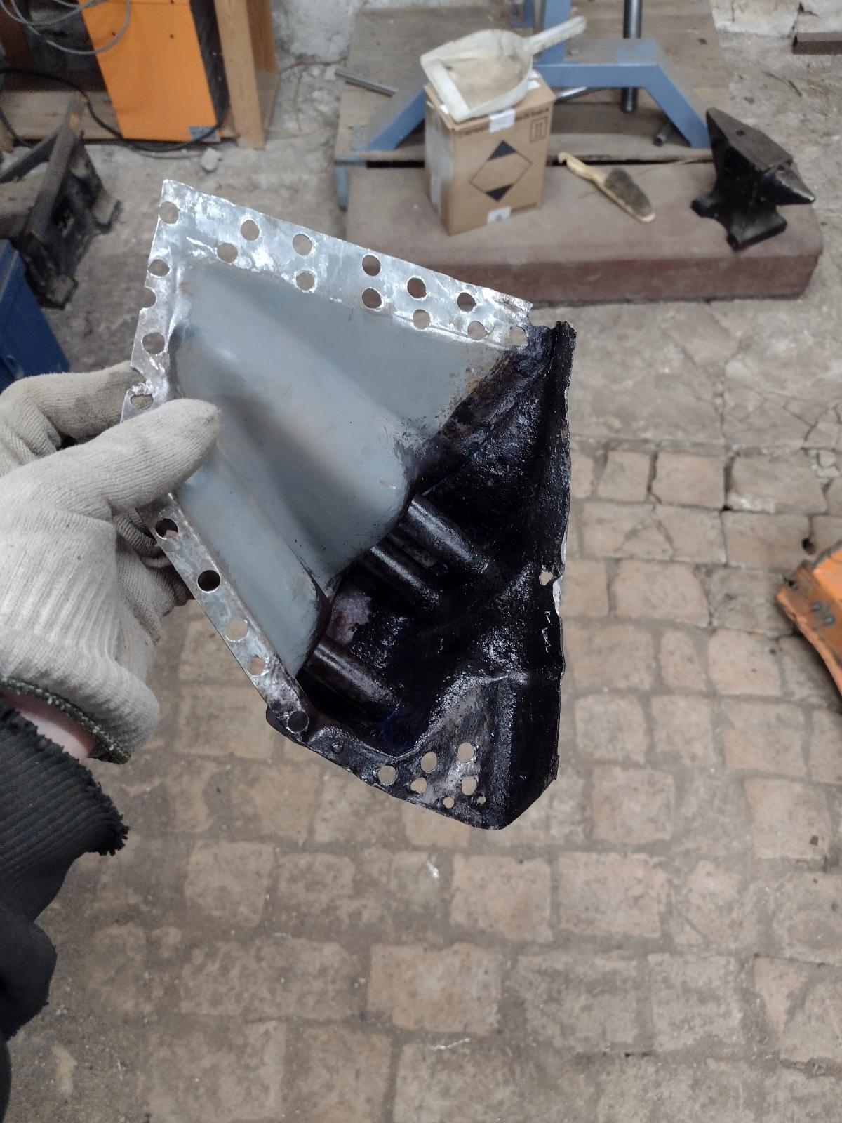
And some paint.. won't move anymore !!
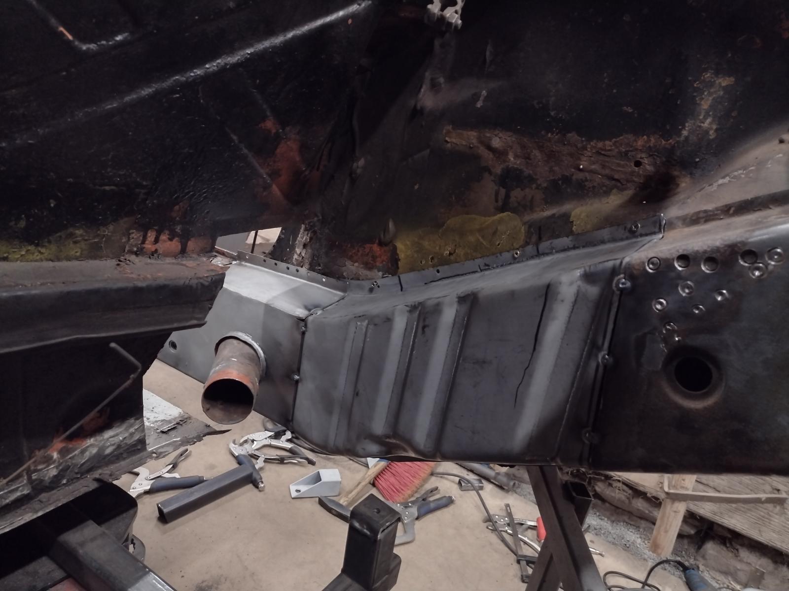
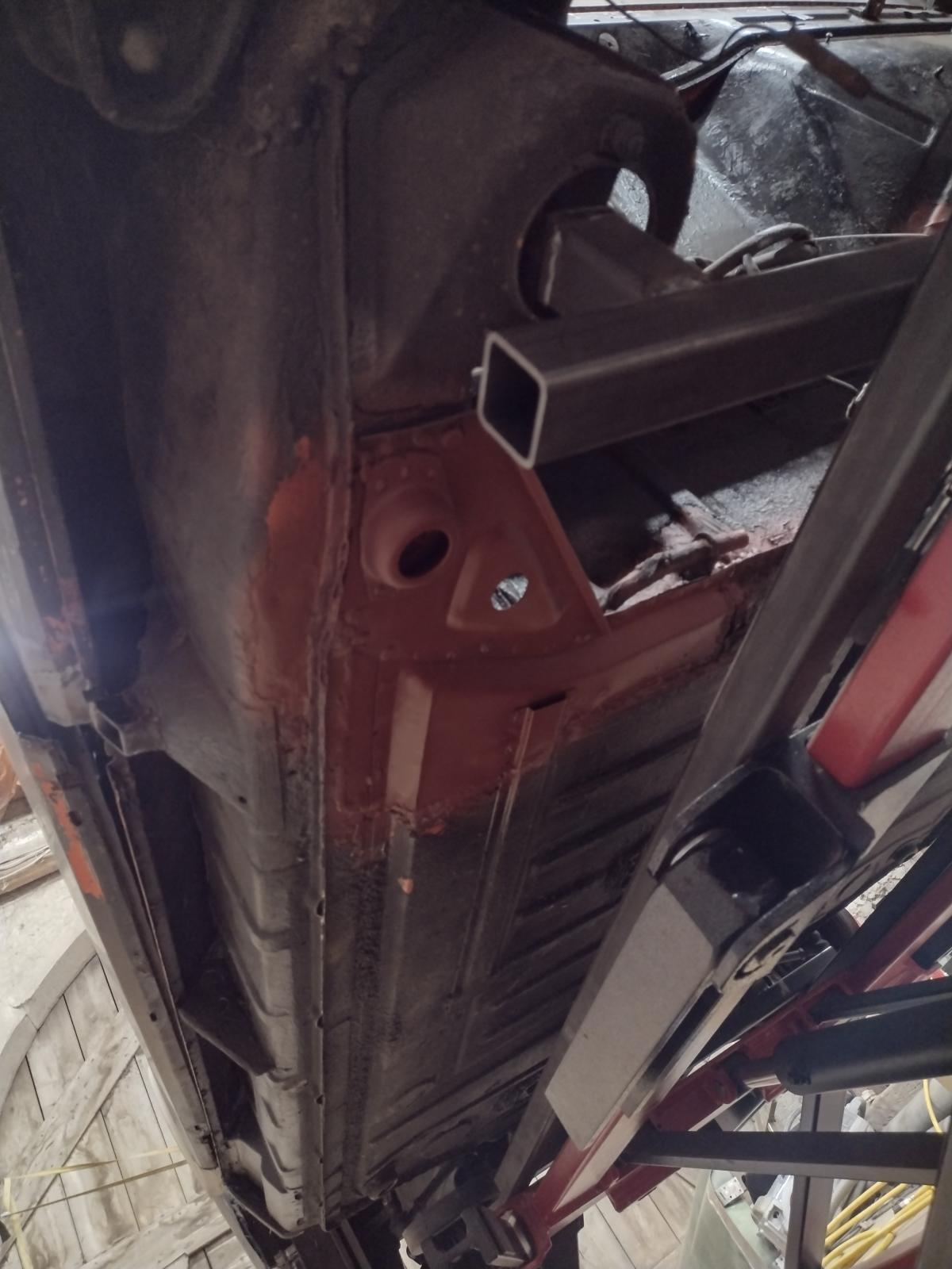
Then after 1000 measurements, checking, positioning,....I welded the inner suspension console ! (And the small bracket for the brake line):
And treated the inside of the long with rust protection product and some paint..here again it will probably last longer than me!!
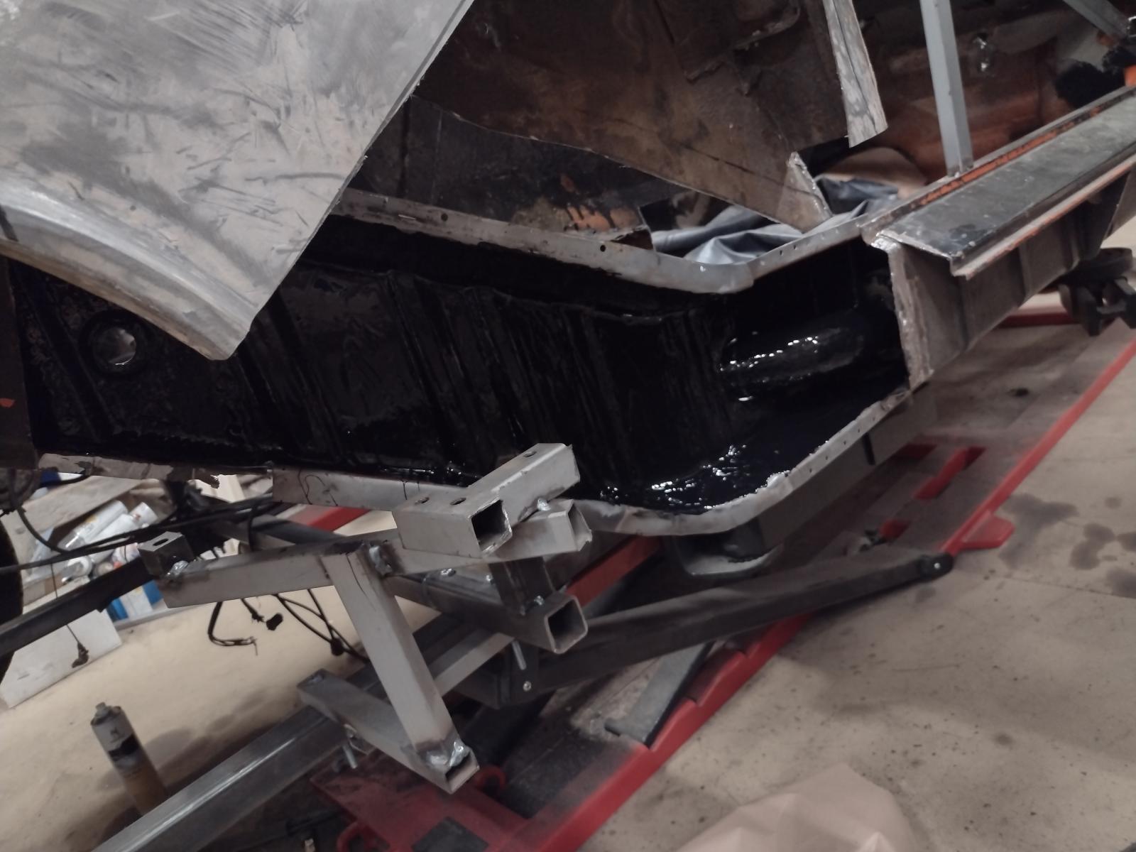
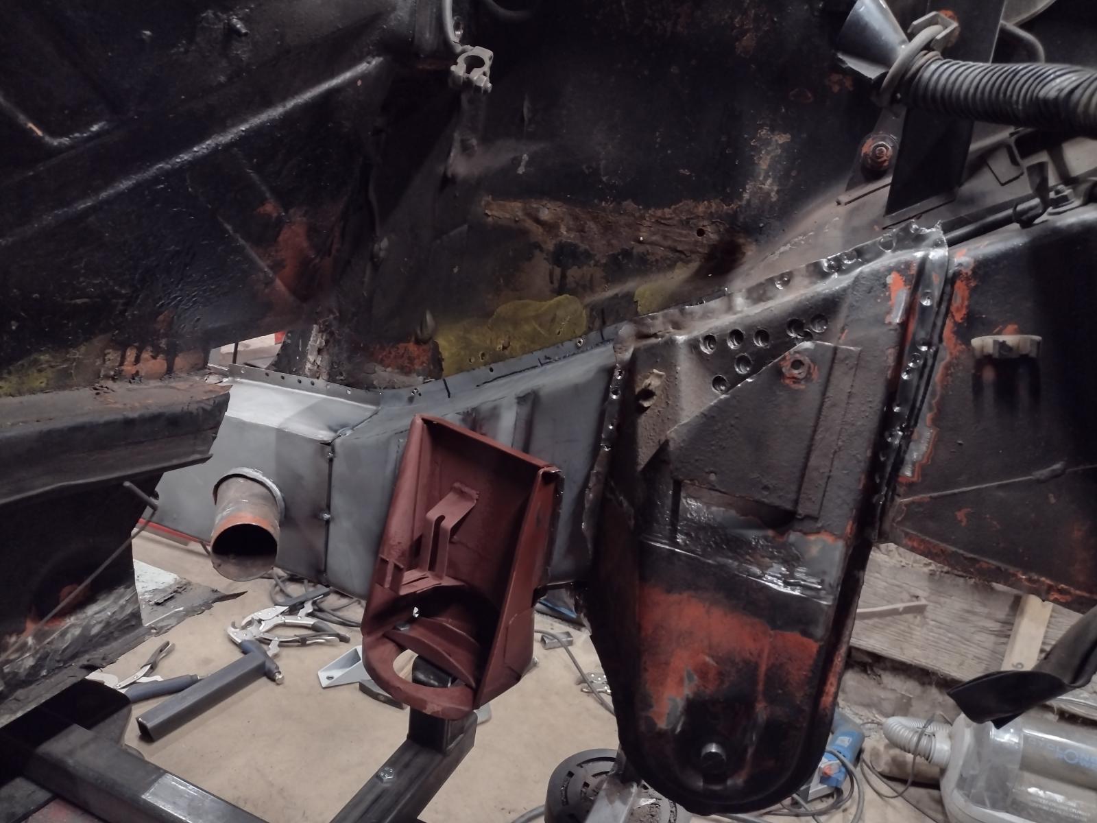
Then it's time to start on the outside :
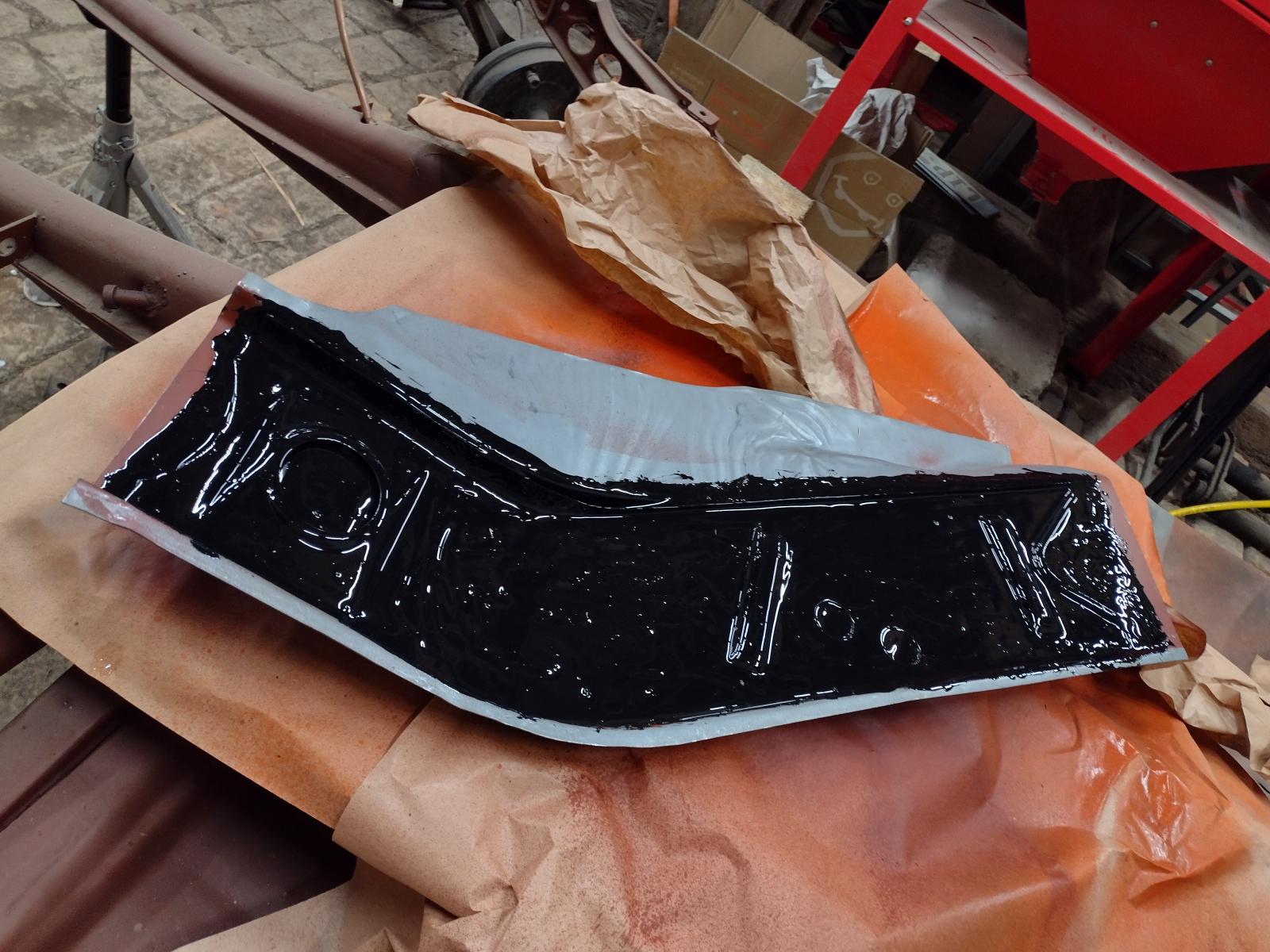
First I treated the outside part with some rust protection primer (I even diluted some to make it fluid enough to go between the layers..):
And then some rust protection paint (also made it fluid to flow everywhere possible as a first layer, then thick over it)
And time to start adjusting:
Lot of adjustment left but the motivation picture:
Stay tuned
Antoine
I managed to work some hours on it this week!
I disassemble my new to me outer suspension console and cleaned/blasted it :
The inside showed only some surface rust :
Except these small holes:
That I welded shut :
I then treated the inside with some rust protection :
And some paint.. won't move anymore !!
Then after 1000 measurements, checking, positioning,....I welded the inner suspension console ! (And the small bracket for the brake line):
And treated the inside of the long with rust protection product and some paint..here again it will probably last longer than me!!
Then it's time to start on the outside :
First I treated the outside part with some rust protection primer (I even diluted some to make it fluid enough to go between the layers..):
And then some rust protection paint (also made it fluid to flow everywhere possible as a first layer, then thick over it)
And time to start adjusting:
Lot of adjustment left but the motivation picture:
Stay tuned
Antoine
Trust you're already doing this, if not, keep track of the entire chassis squareness not just the local position of the suspension console.
Getting that outer console located properly is key to wheelbase, camber, and toe.
Triple check and then check again before final welding.
Learn from my mistake. Somewhere along the line I got over anxious and ended up with 4.3mm of shrinkage in Z height. Weld slowly. I now cool every weld to near room temp before proceeding to the next and haven't had a problem since. It's painfully slow but better than shrinking something.
[quote name='Superhawk996' date='Jan 7 2022, 02:06 PM' post='2972772']
Trust you're already doing this, if not, keep track of the entire chassis squareness not just the local position of the suspension console.
Getting that outer console located properly is key to wheelbase, camber, and toe.
Triple check and then check again before final welding.

That console piece candidate turned out really nice. Nice rustproofing technique.
Were you able to save the tie in pieces? Obviously your skilled to make new ones.
Very nice progress.
Trust you're already doing this, if not, keep track of the entire chassis squareness not just the local position of the suspension console.
Getting that outer console located properly is key to wheelbase, camber, and toe.
Triple check and then check again before final welding.
That console piece candidate turned out really nice. Nice rustproofing technique.
Were you able to save the tie in pieces? Obviously your skilled to make new ones.
Very nice progress.
Looking great! Keep up the hard work. Very inspiring!
Thanks a lot Dion and Superhawk996, any advice is always worth it !! I am over measuring everything to make sure it stays square and I am forcing me to take even more time but I know it's crucial, thanks again for the reminder !!! Dion, I did not manage to save totally the connecting pieces..but I made some templates of them so either I will repair them or make new ones..we will See what works best
@Freezin914: thanks for following along and happy you like it !
Bests
Antoine
Dion, I did not manage to save totally the connecting pieces..but I made some templates of them so either I will repair them or make new ones..we will See what works best @Freezin914: thanks for following along and happy you like it !
Bests
Antoine
Thanks a lot !!!
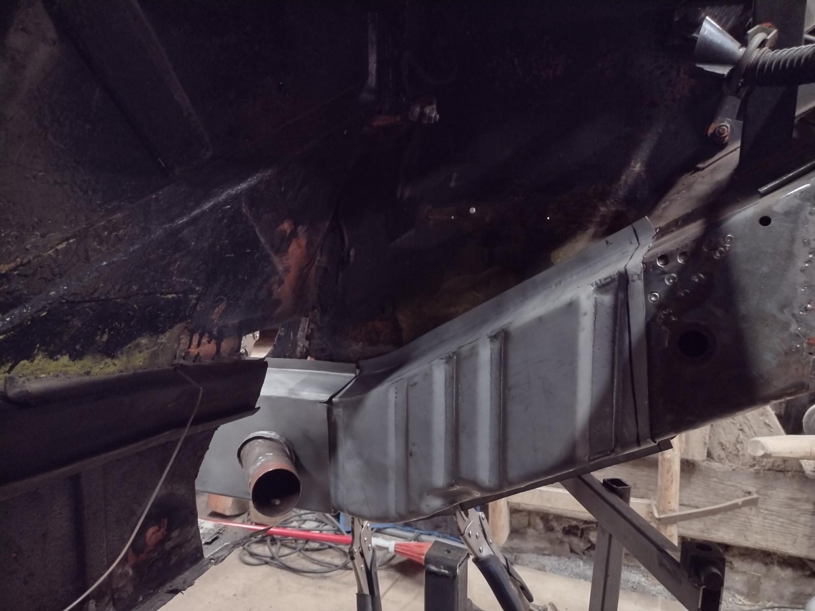
So, long overdue update!
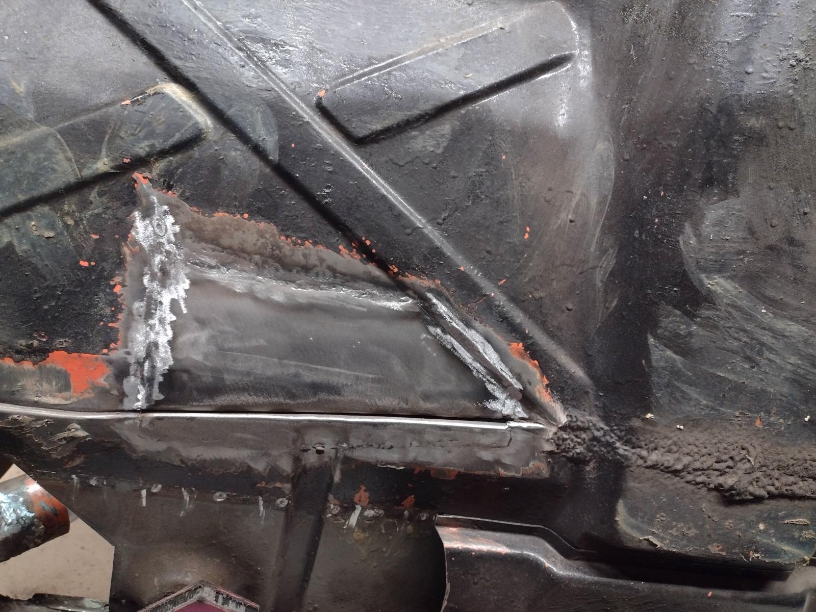
More adjustments, measurements..and welding here:


And fully welded:


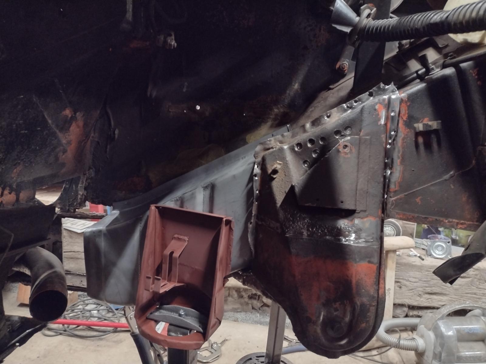
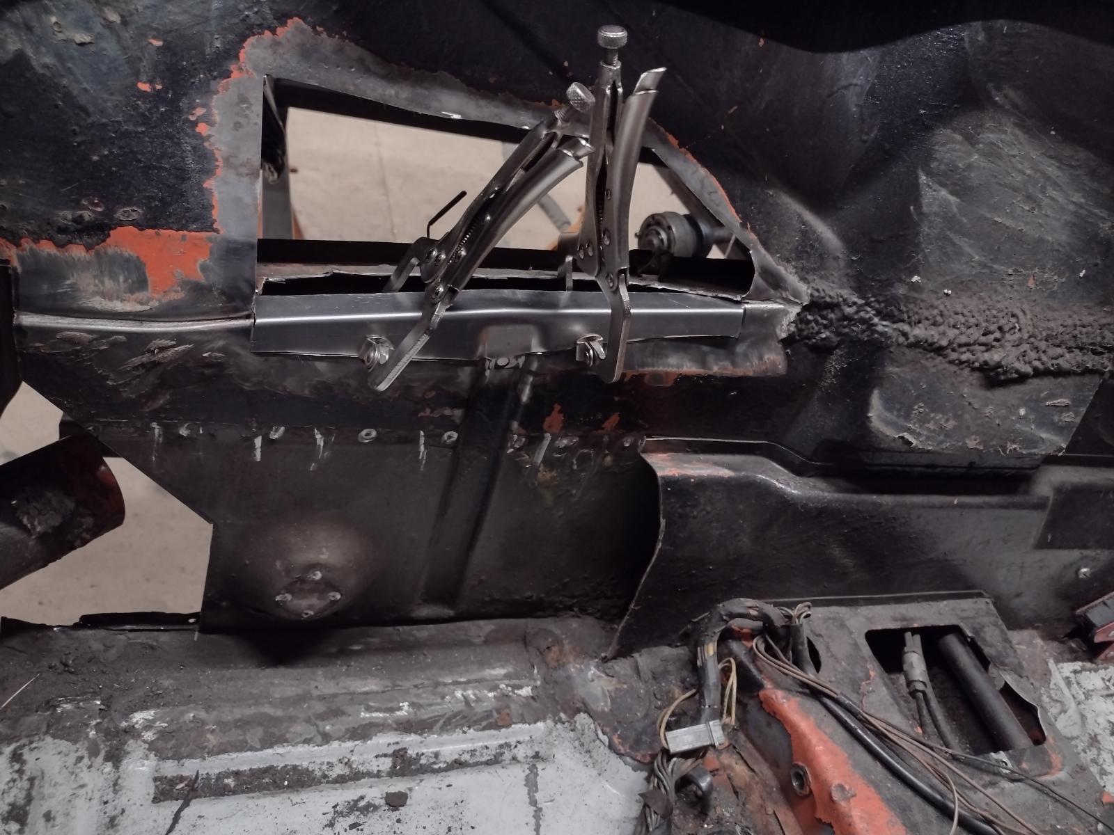
Now adjusting the suspension console :

And all welded including the connecting parts between the consoles:

All measurements are ok and the arm felt right in place:
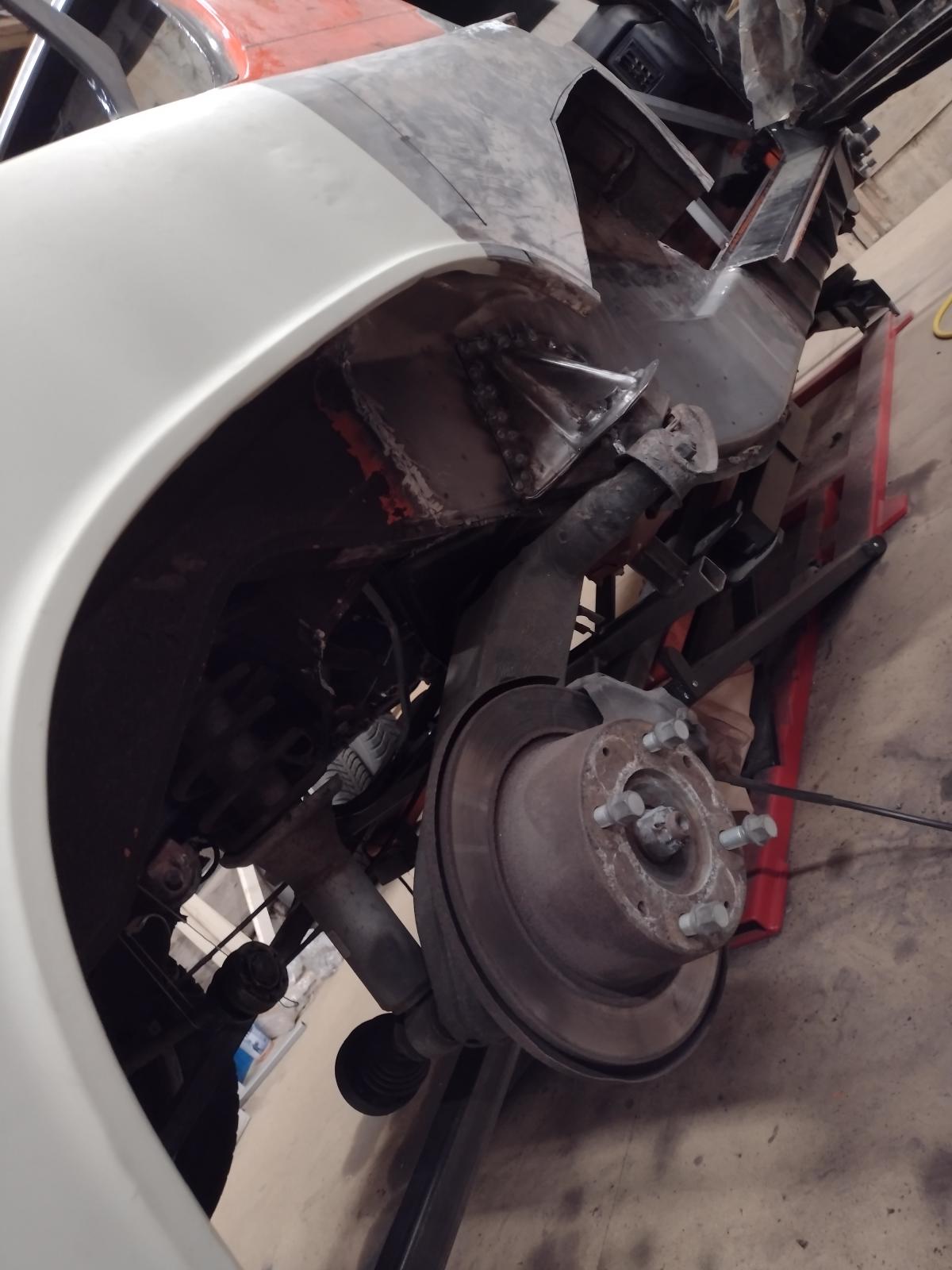
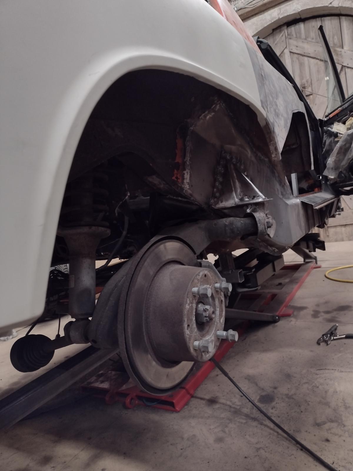
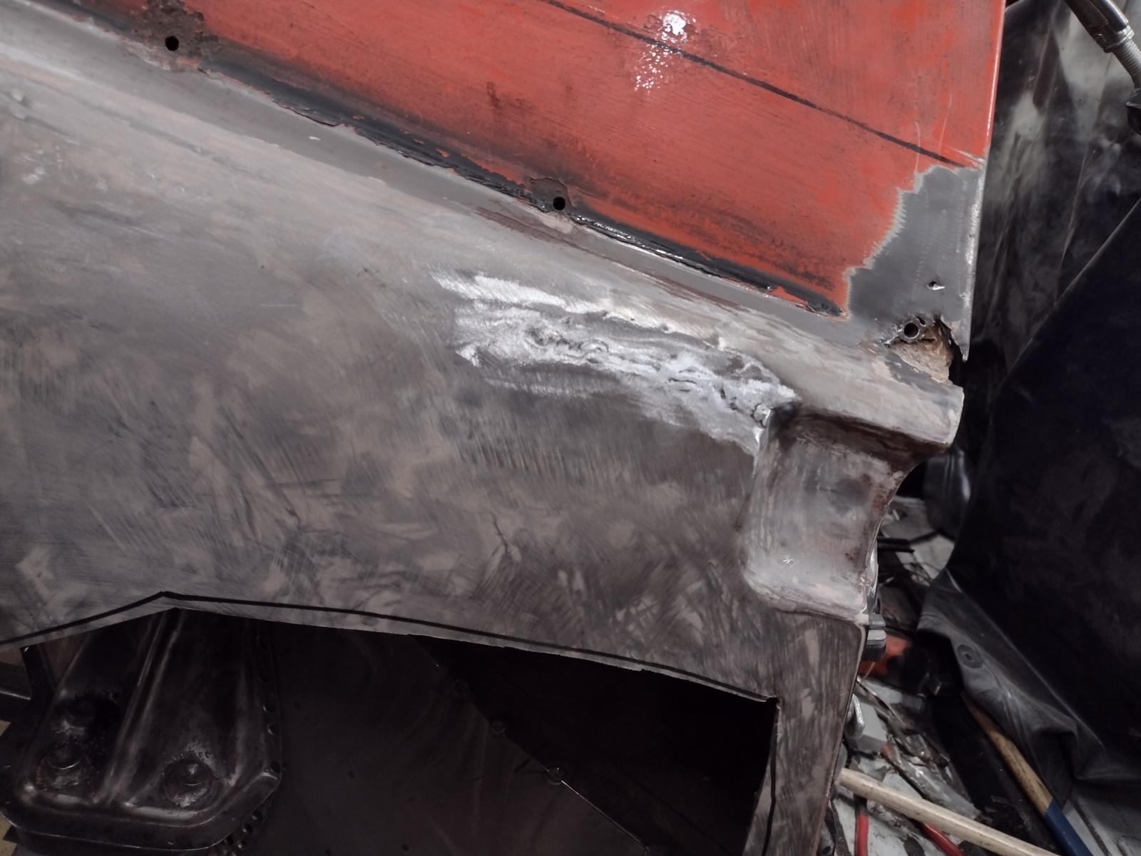
I can tell you that this view was a real relief !!
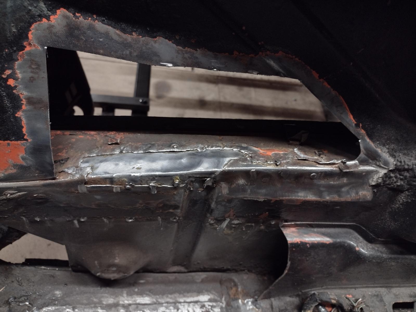
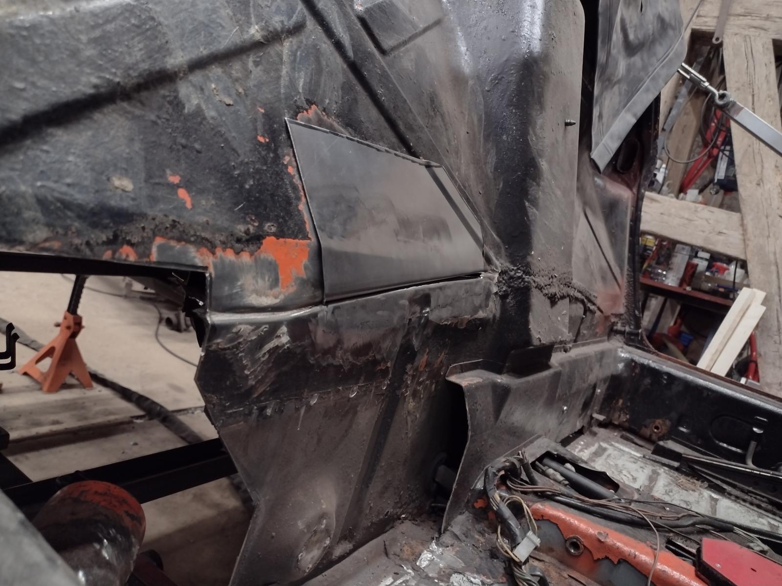
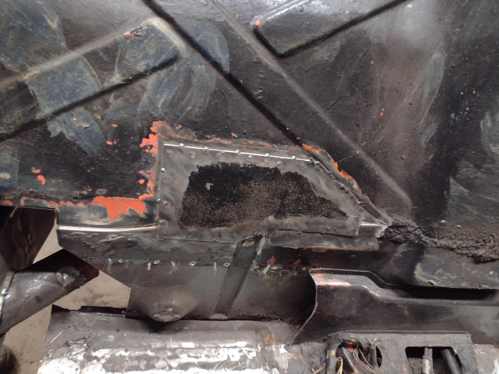
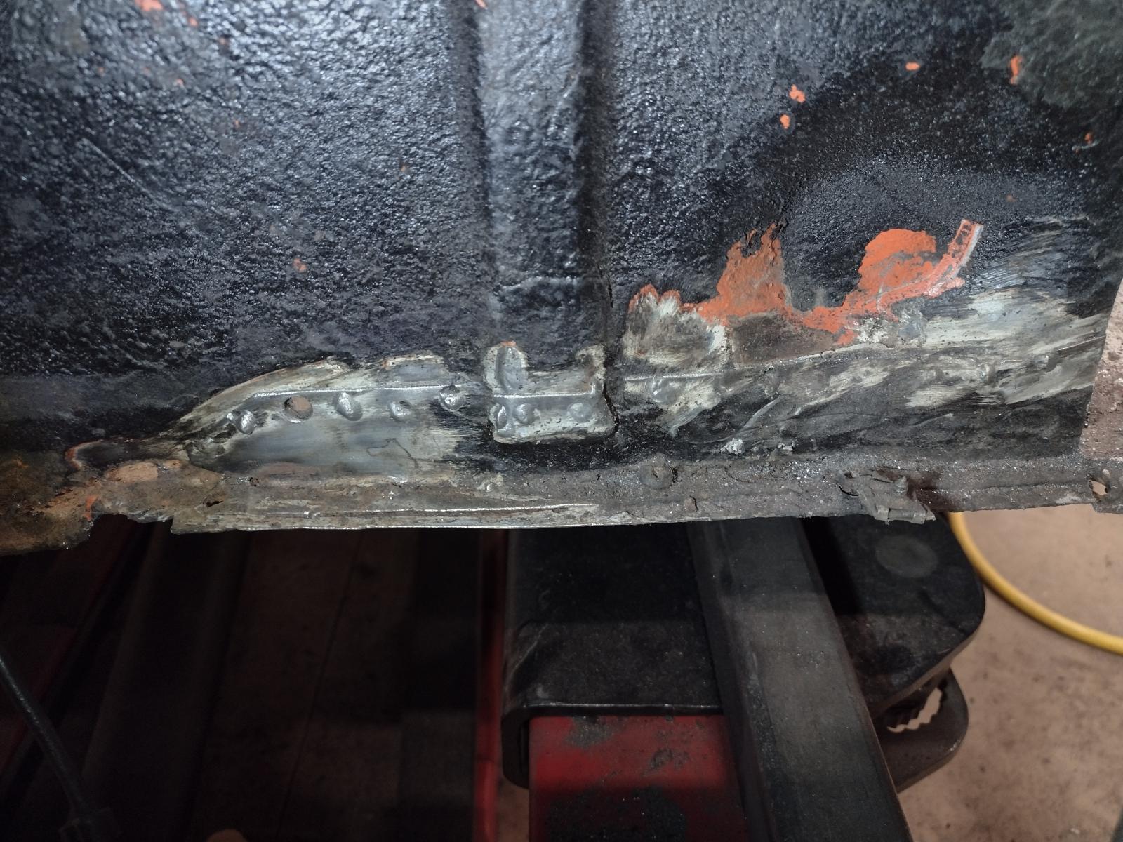
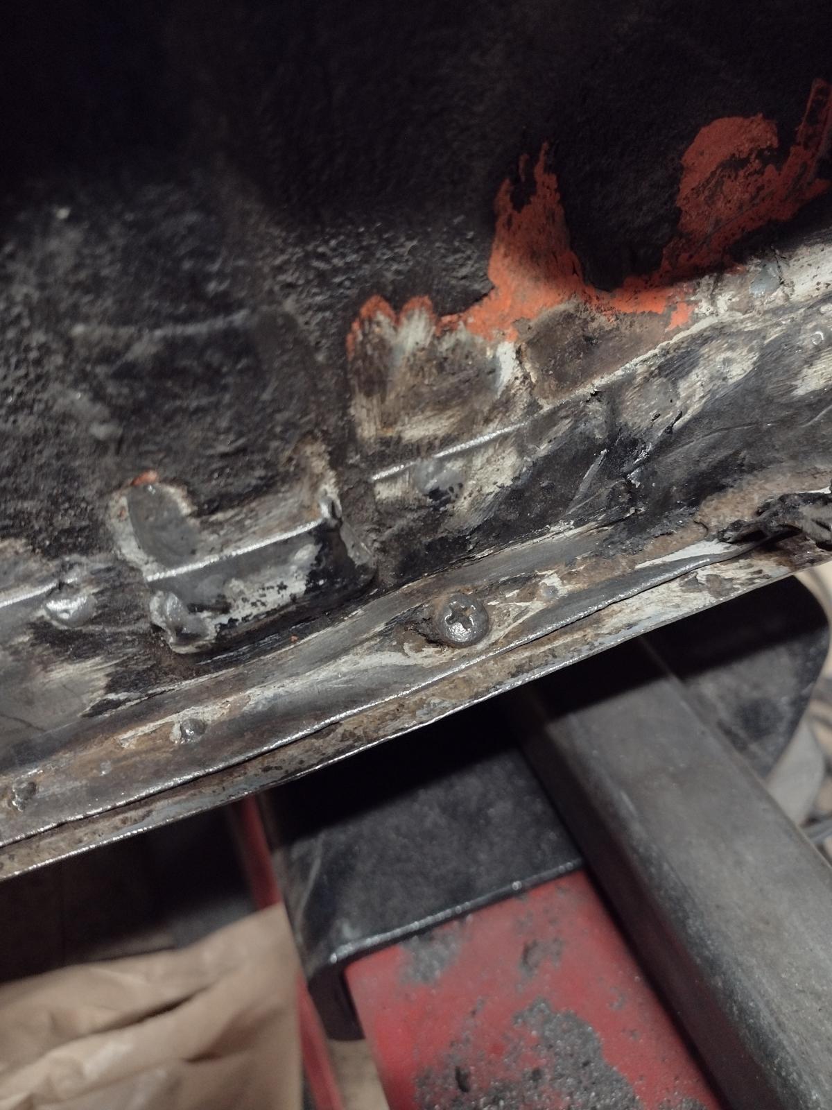
But still lots to do, like here with this poor repair:

And behind it some metal put under the rust..

So big cleaning :
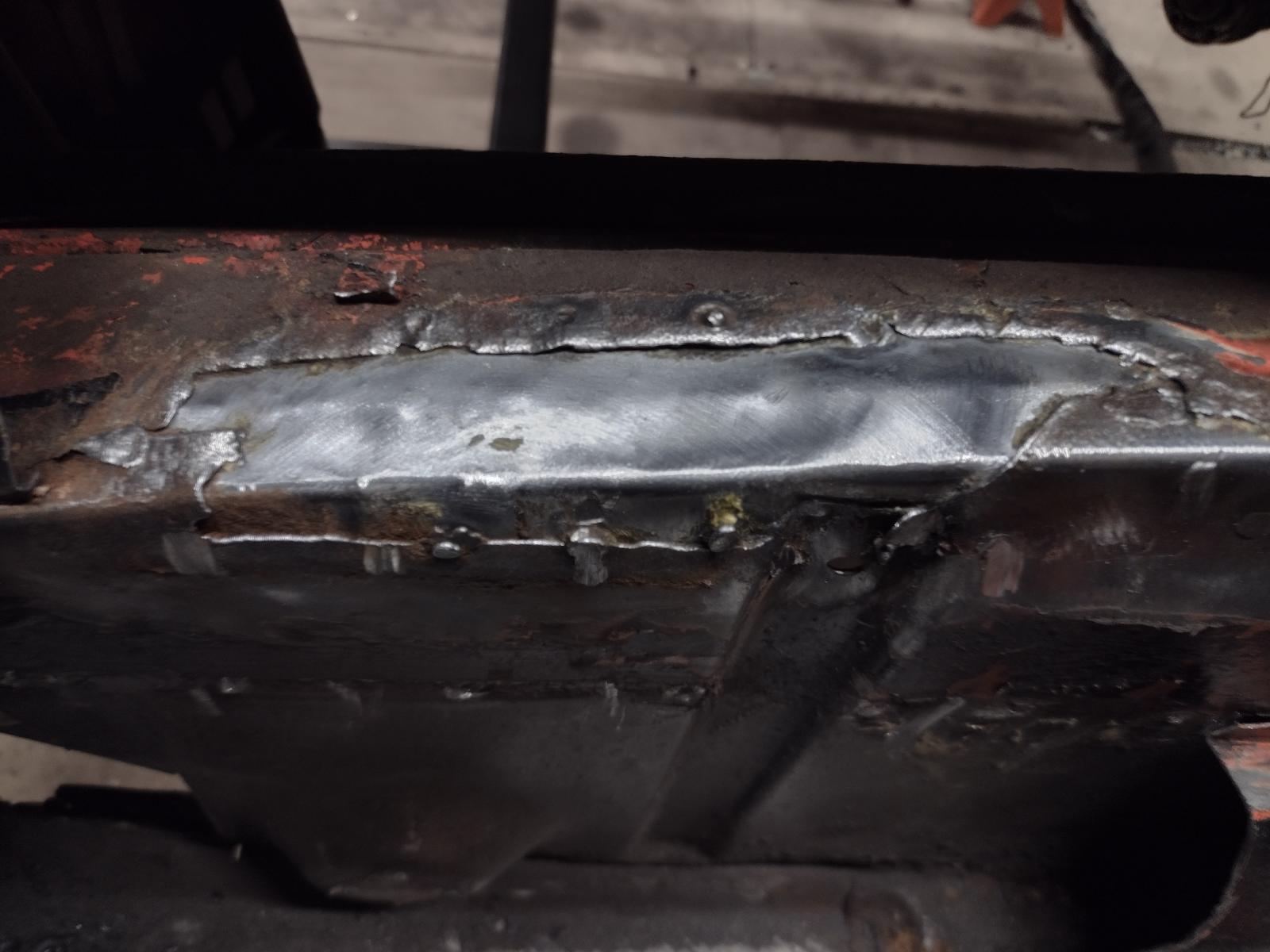
Adjusting the bottom part:

And welded:


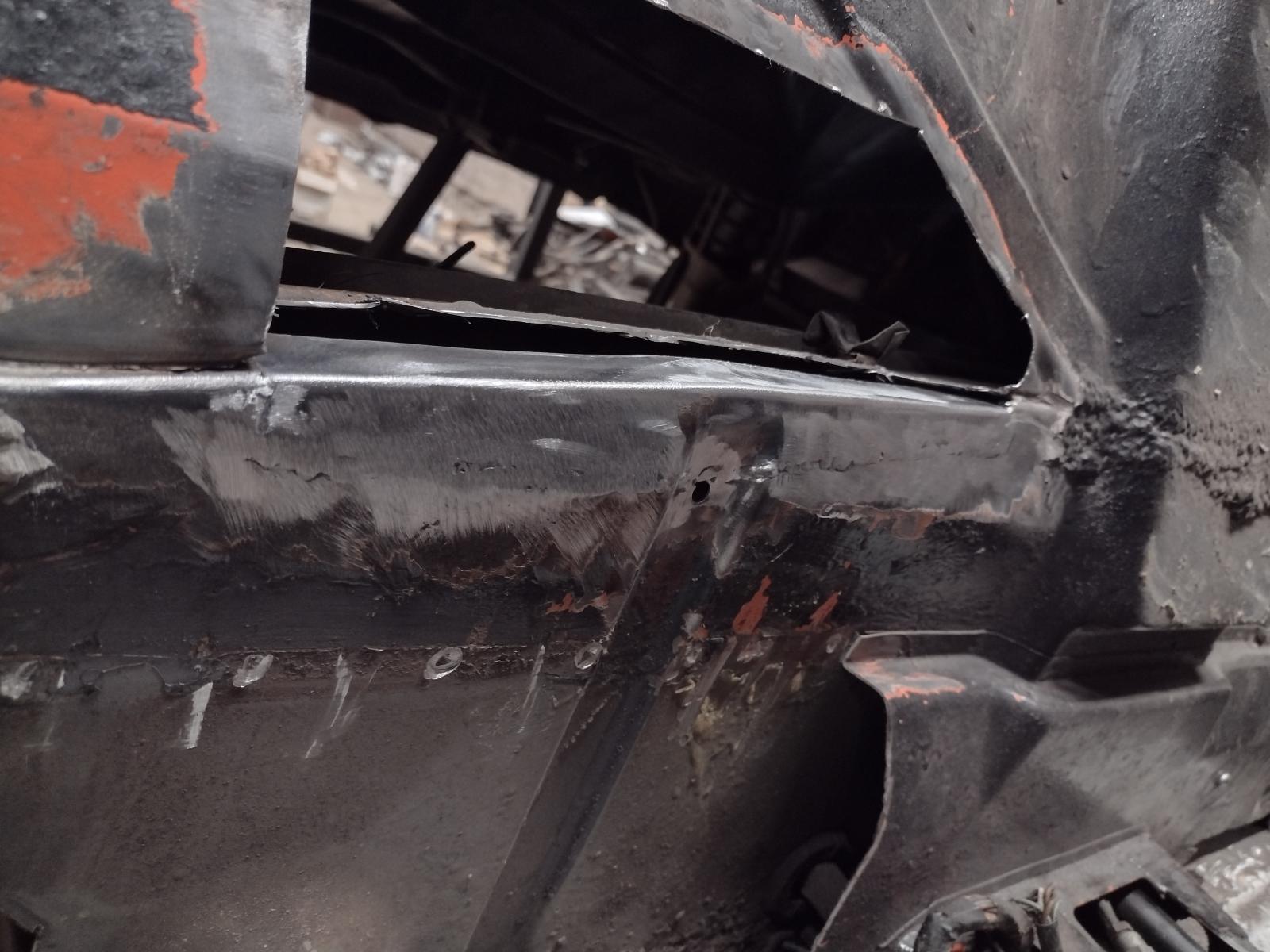
And the top part:


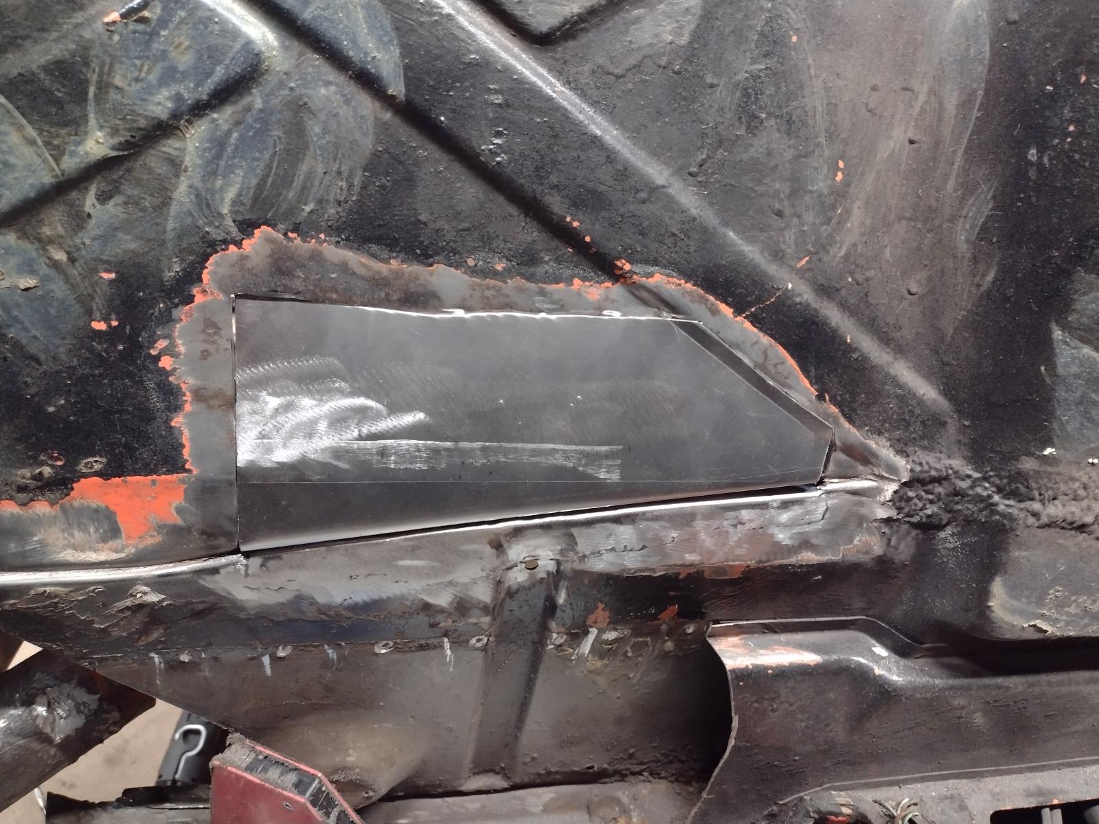
And welded:

Next update will follow very soon !
Antoine
So, long overdue update!
More adjustments, measurements..and welding here:
And fully welded:
Now adjusting the suspension console :
And all welded including the connecting parts between the consoles:
All measurements are ok and the arm felt right in place:
I can tell you that this view was a real relief !!
But still lots to do, like here with this poor repair:
And behind it some metal put under the rust..
So big cleaning :
Adjusting the bottom part:
And welded:
And the top part:
And welded:
Next update will follow very soon !
Antoine
So, long overdue update!
More adjustments, measurements..and welding here:


And fully welded:
Now adjusting the suspension console :

And all welded including the connecting parts between the consoles:
All measurements are ok and the arm felt right in place:


I can tell you that this view was a real relief !!
But still lots to do, like here with this poor repair:
And behind it some metal put under the rust..

So big cleaning :

Adjusting the bottom part:

And welded:
And the top part:


And welded:

Next update will follow very soon !
Antoine
More adjustments, measurements..and welding here:
And fully welded:
Now adjusting the suspension console :
And all welded including the connecting parts between the consoles:
All measurements are ok and the arm felt right in place:
I can tell you that this view was a real relief !!
But still lots to do, like here with this poor repair:
And behind it some metal put under the rust..
So big cleaning :
Adjusting the bottom part:
And welded:
And the top part:
And welded:
Next update will follow very soon !
Antoine
Yup, all those repairs look very familiar to me.
You're cranking along nicely. I hope spring comes for your early this year so that you won't be working in that cold work space!
Keep going!
You're cranking along nicely. I hope spring comes for your early this year so that you won't be working in that cold work space!
Keep going!
Thanks a lot! Sure, warmer temperature would be great but hey, I am still lucky to have a shop to enjoy this passion!
So...next update!
Before taking care of the bottom of the passenger rear quarter, I thought I will see what I can do with the top part with the holes and dents:
I first planished it roughly with hammer and dollies:
And welded the holes shut. Some smoothing left but already way better:
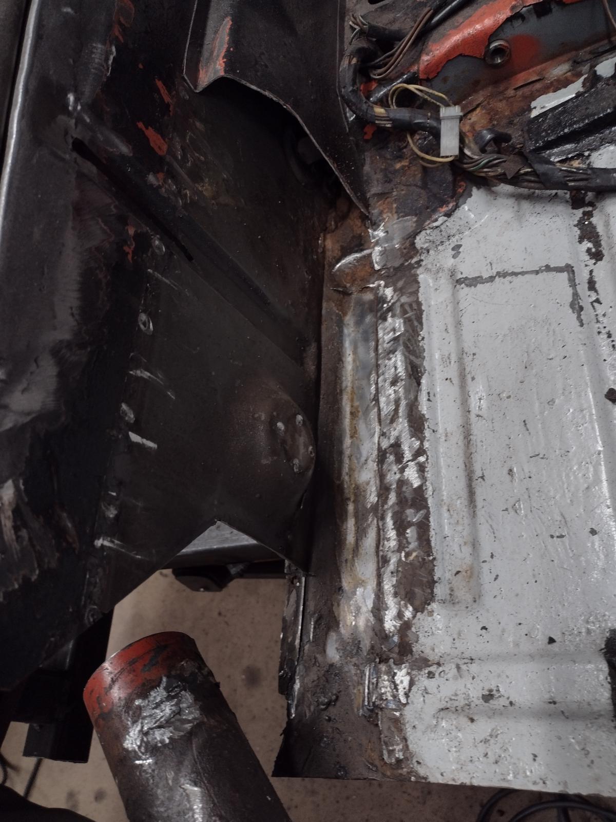
Then I decided to continue on the firewall..first taking care of this old terrible repair:
I decided to replace this part:
Making a template:
And the patch :
Cut out the wrong repair:
Adjusting:
Welding:
Et voilà:
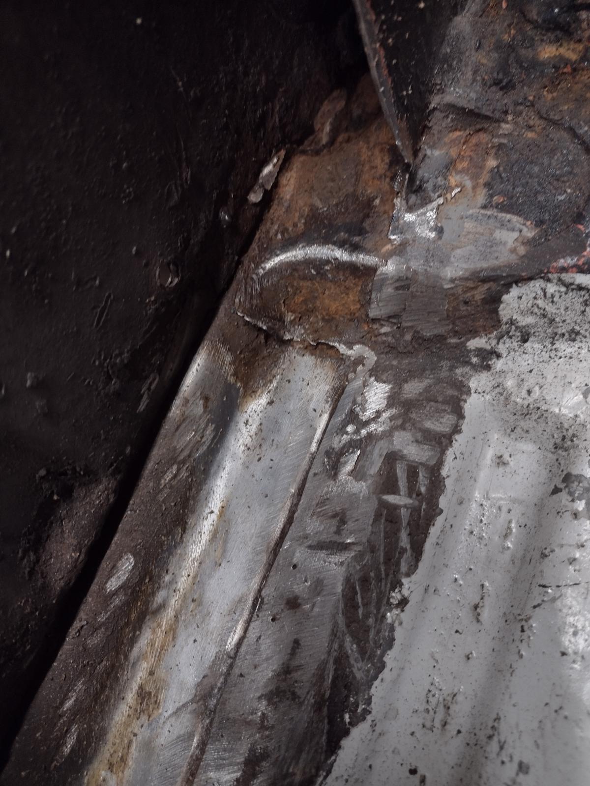
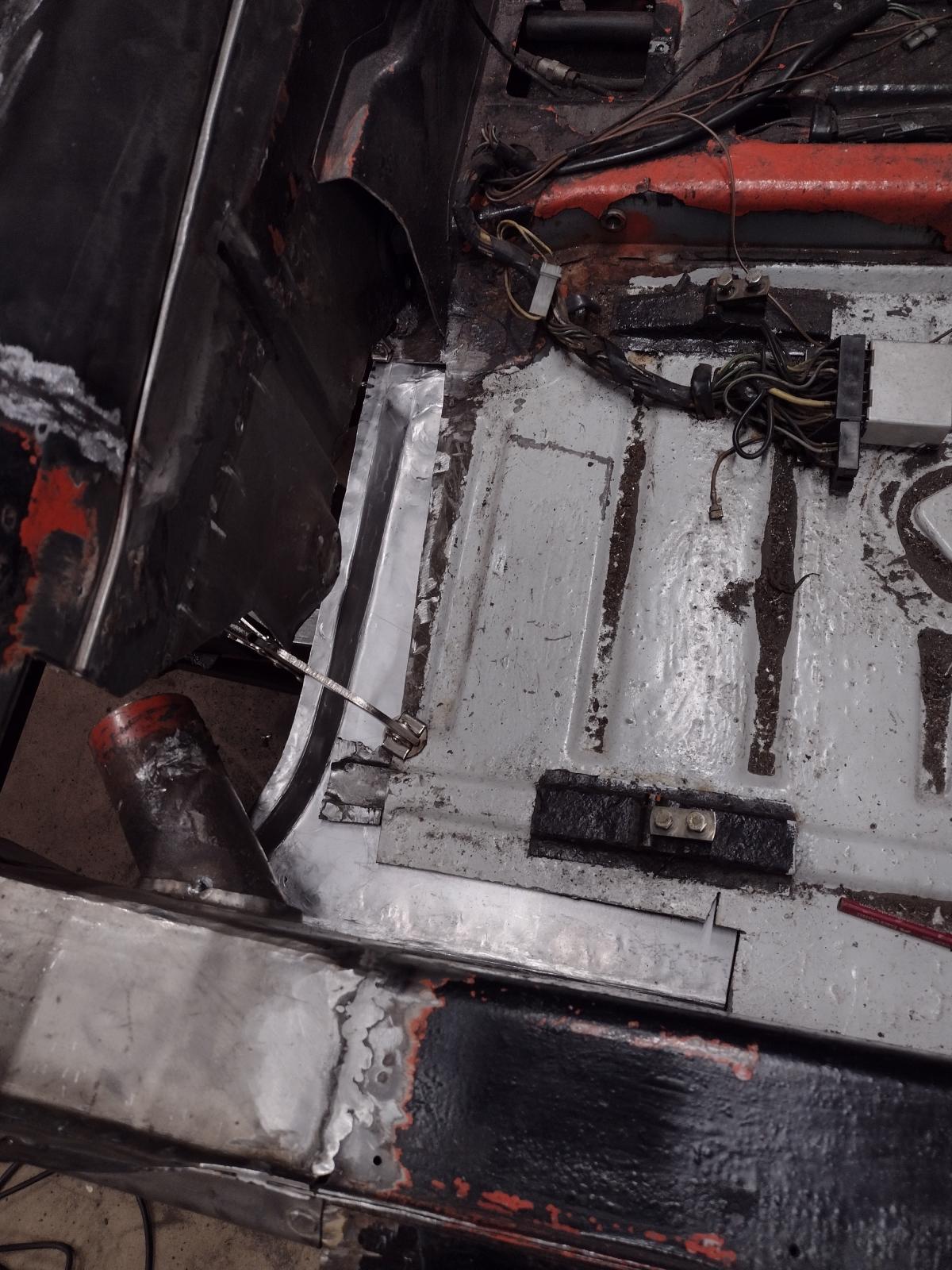
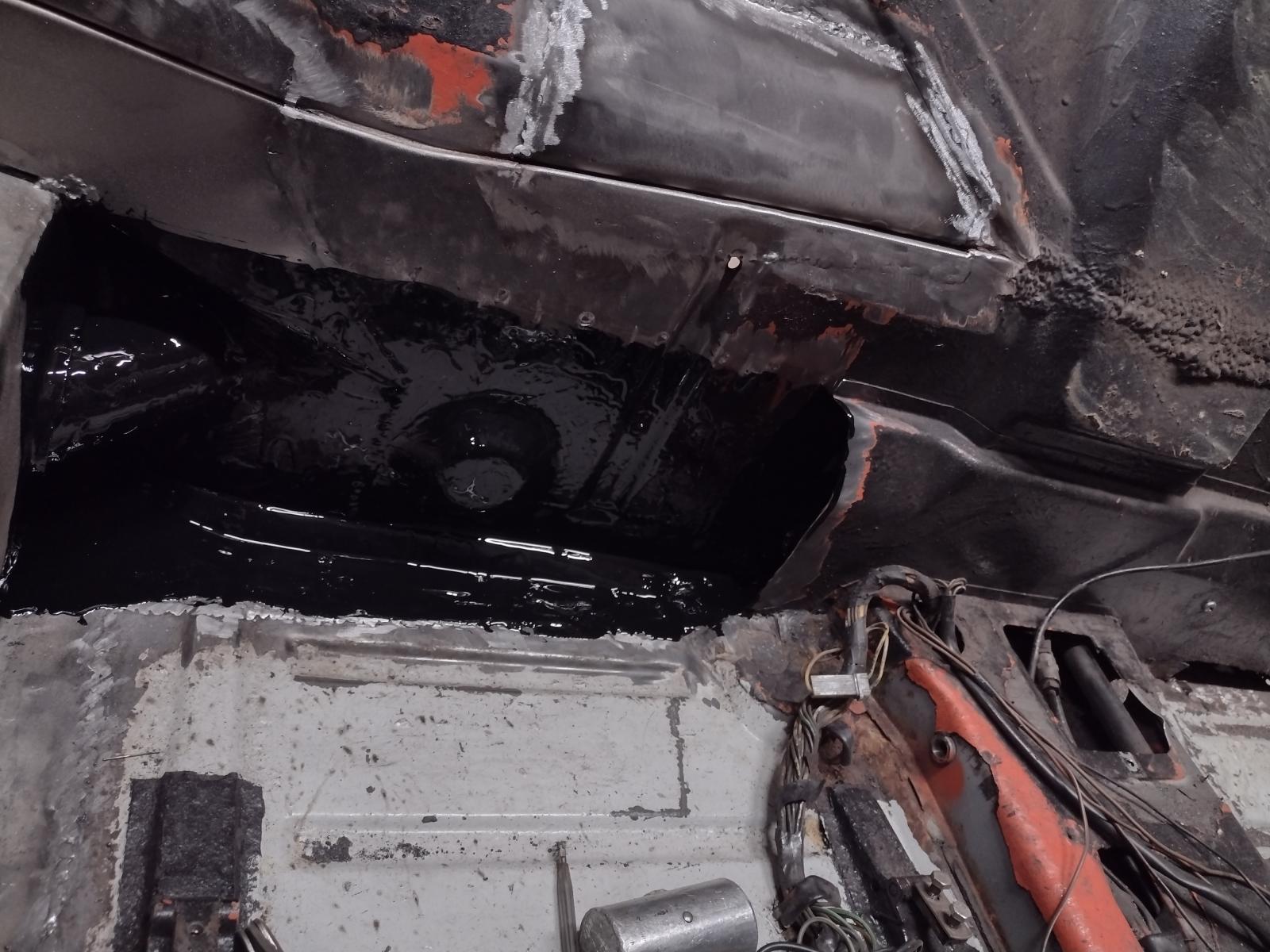
And in between, I had noticed that the floor was also repaired with metal over rust, what I can't stand so I also fixed that:
How it was:
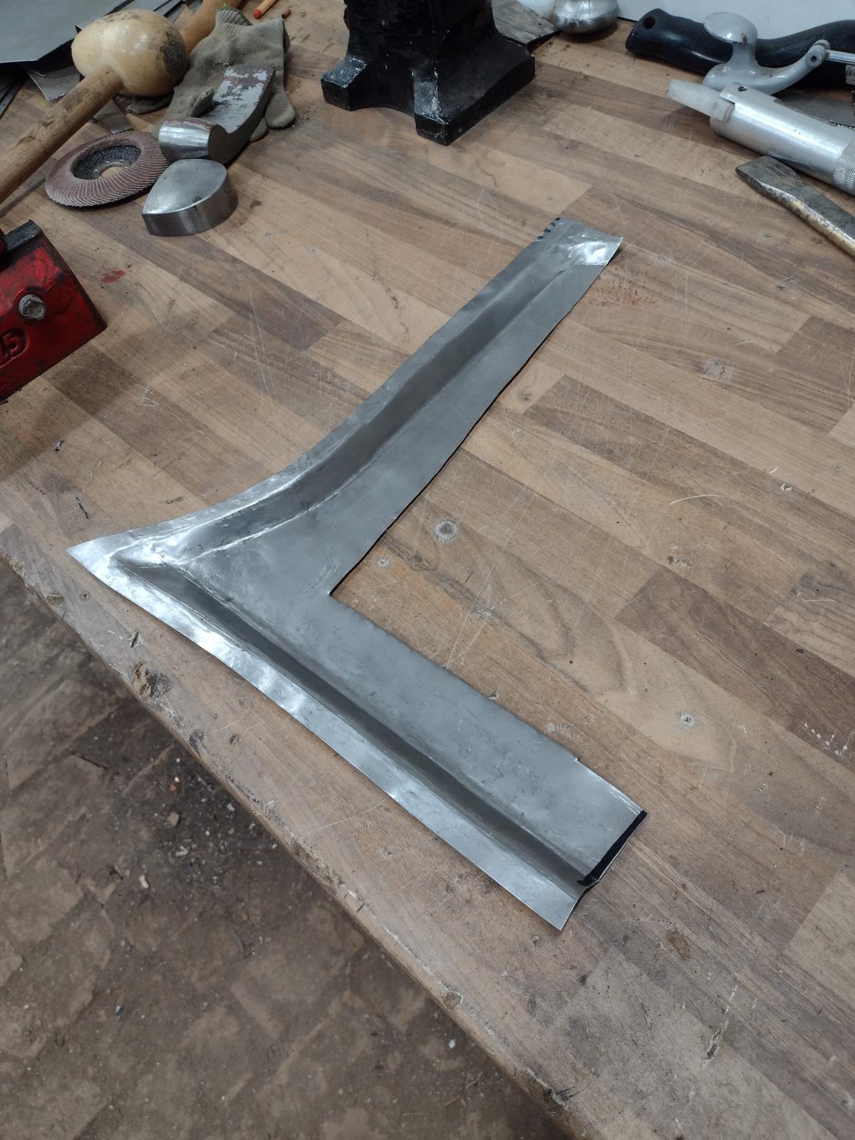
Starting the shape:
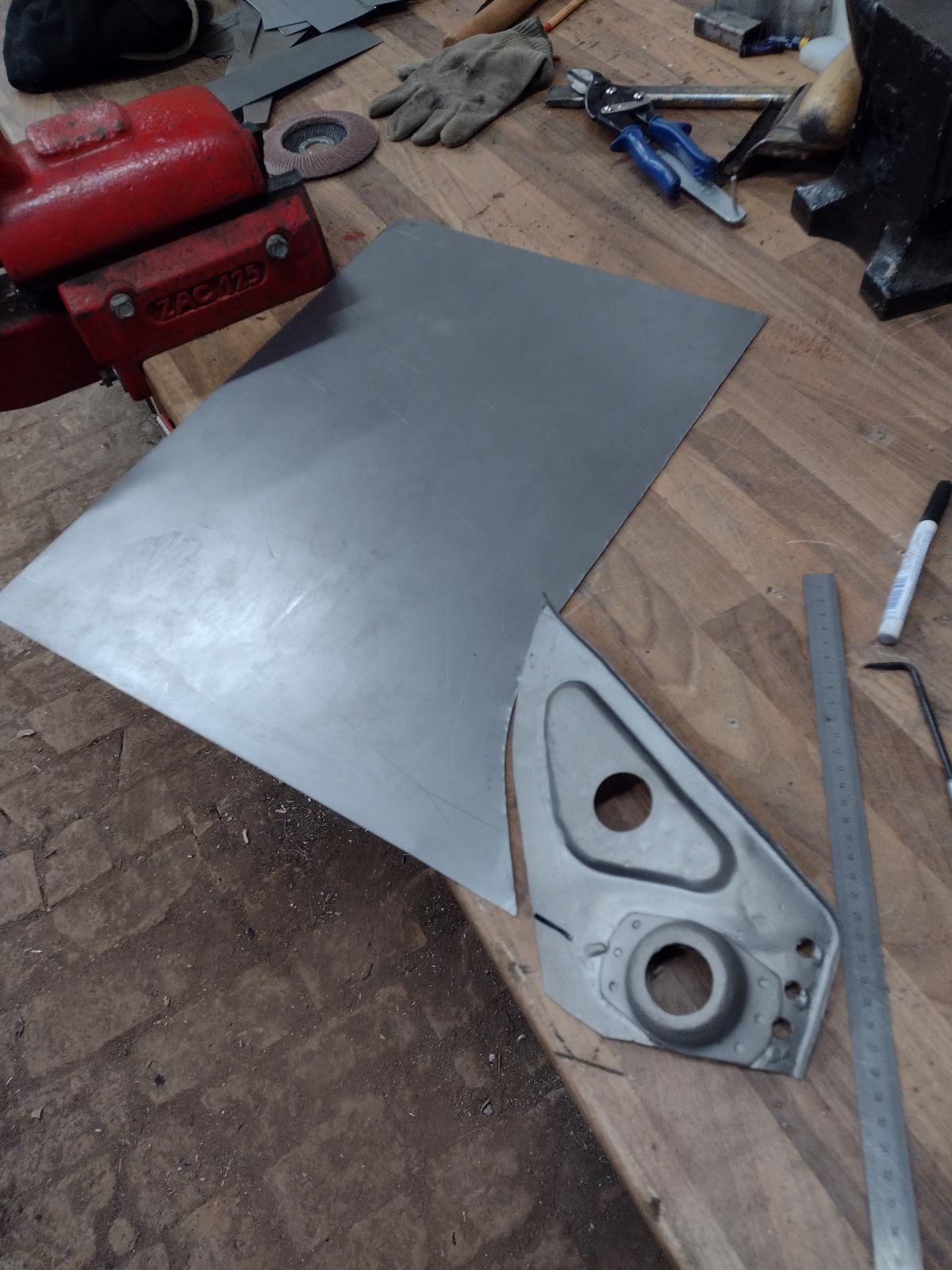
Verifying the fit:
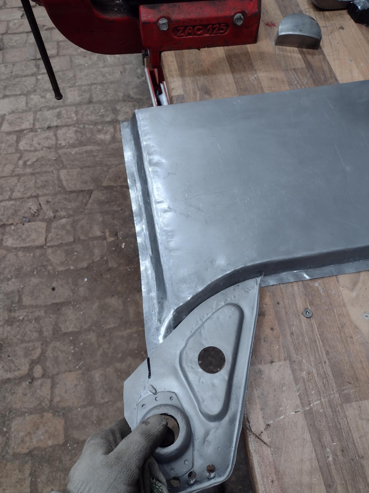
Whole shape:
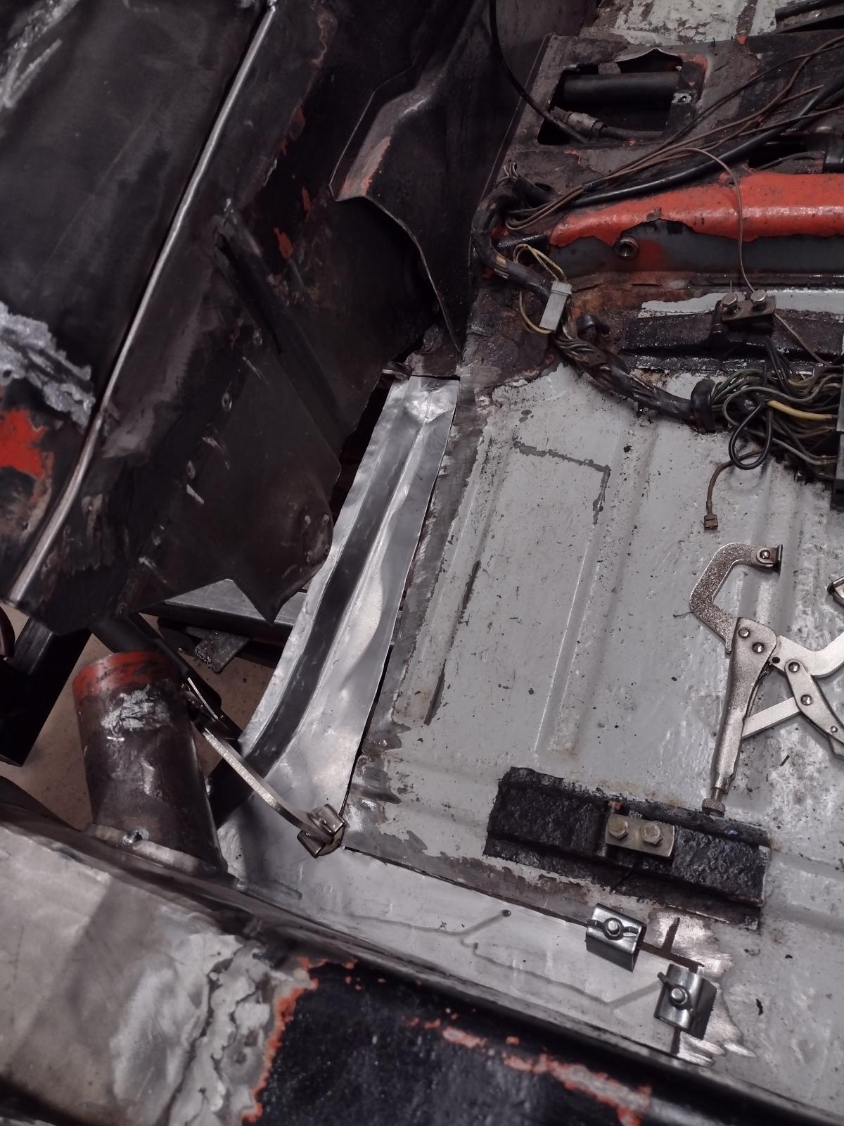
Test-fitting:
Cutting and adjusting:
And welded:
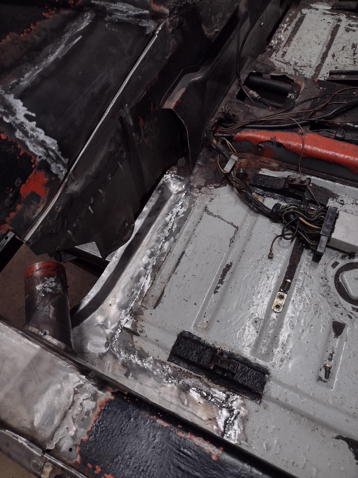
I did not over-grind it..the weld is under the front part of the firewall and robustness is more important!
Stay tuned, I have more to share!
Antoine
So...next update!
Before taking care of the bottom of the passenger rear quarter, I thought I will see what I can do with the top part with the holes and dents:
I first planished it roughly with hammer and dollies:
And welded the holes shut. Some smoothing left but already way better:
Then I decided to continue on the firewall..first taking care of this old terrible repair:
I decided to replace this part:
Making a template:
And the patch :
Cut out the wrong repair:
Adjusting:
Welding:
Et voilà:
And in between, I had noticed that the floor was also repaired with metal over rust, what I can't stand so I also fixed that:
How it was:
Starting the shape:
Verifying the fit:
Whole shape:
Test-fitting:
Cutting and adjusting:
And welded:
I did not over-grind it..the weld is under the front part of the firewall and robustness is more important!
Stay tuned, I have more to share!
Antoine
Great fabrication! Looking really nice. It seems like quick progress. Keep rocking it out.
@TRS63 Antoine - Most excellent passion and effort; I'm really enjoying your adventure and admiring your patience and work.
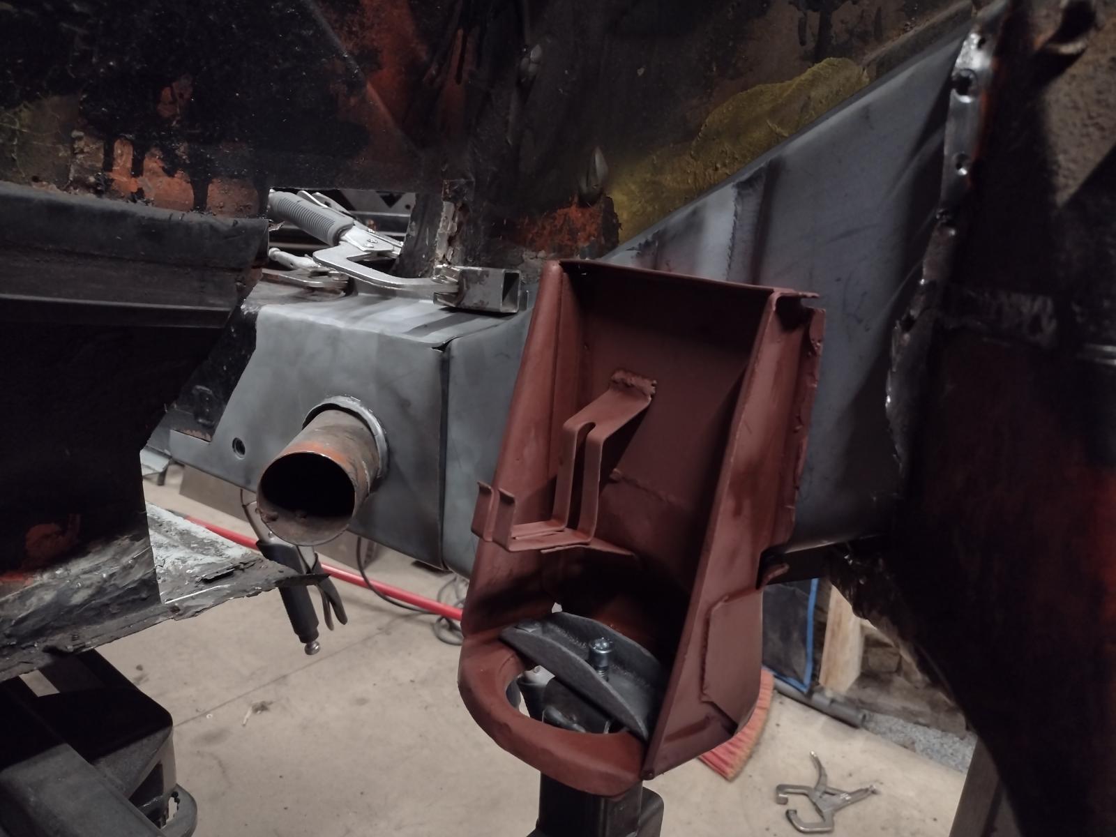
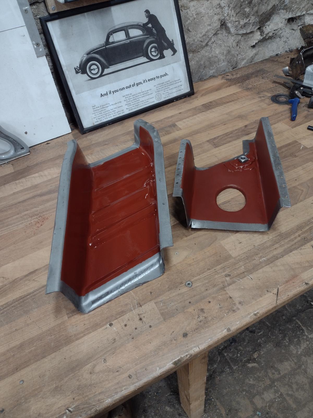
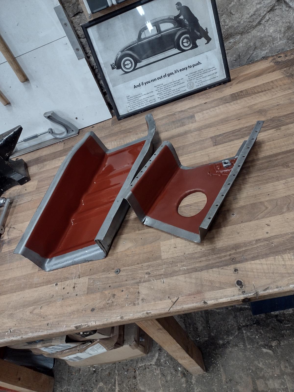
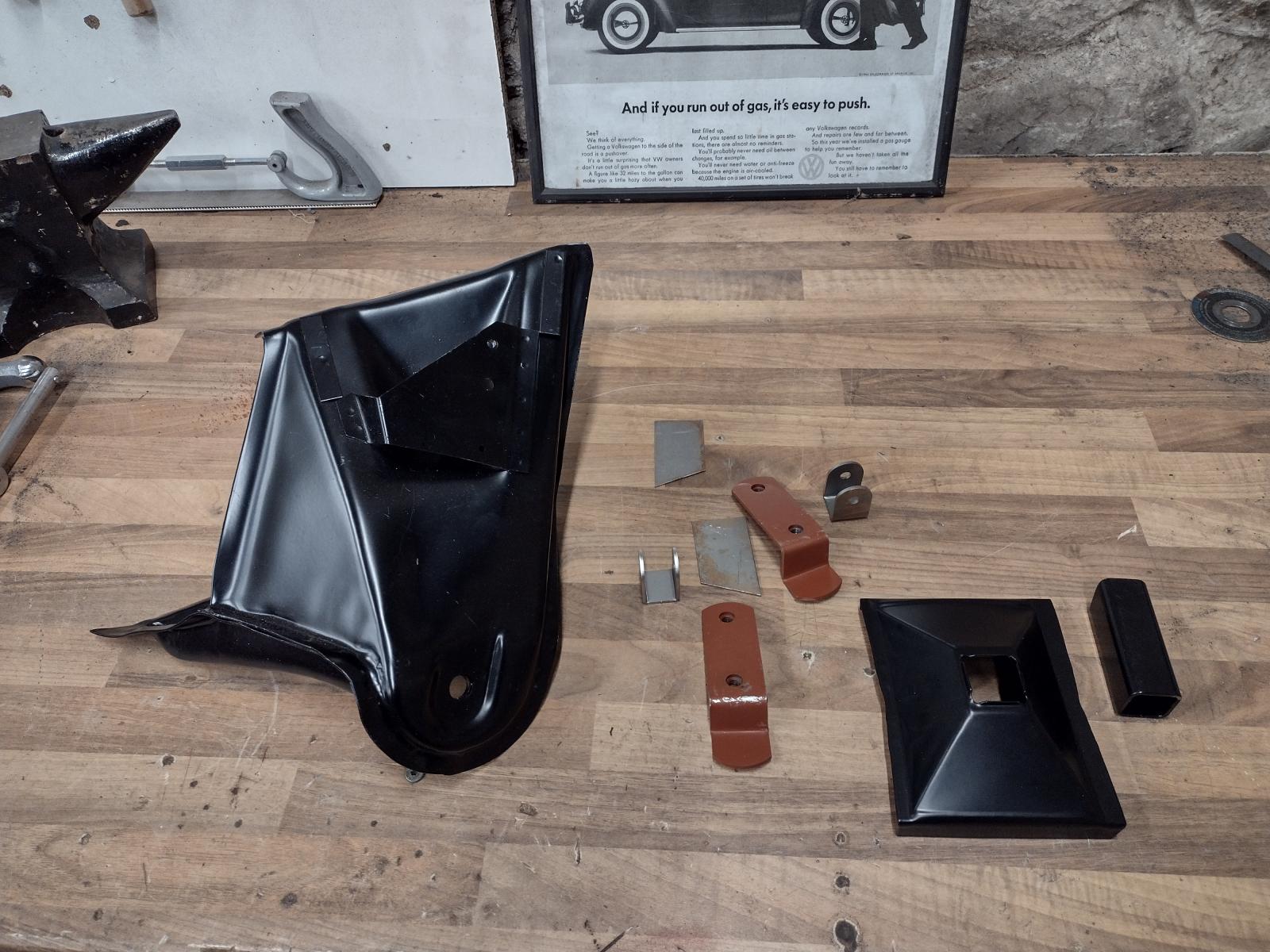
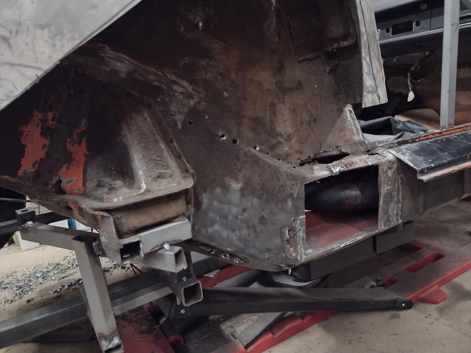
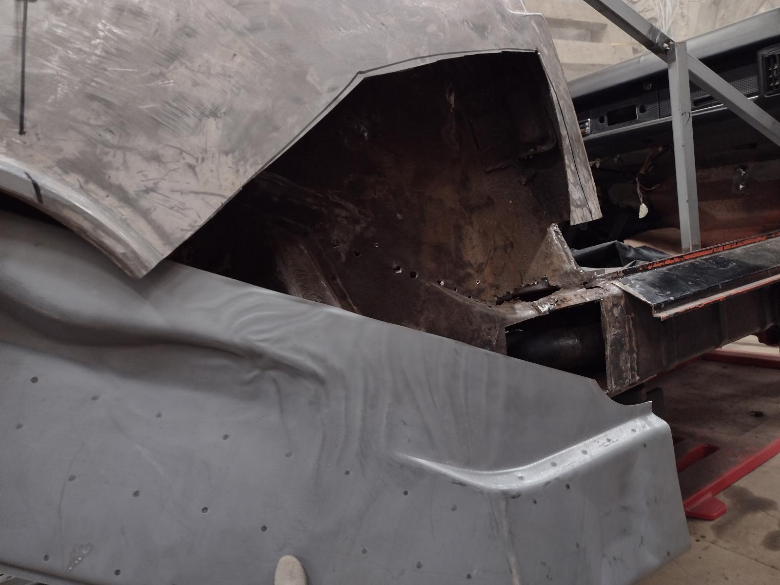
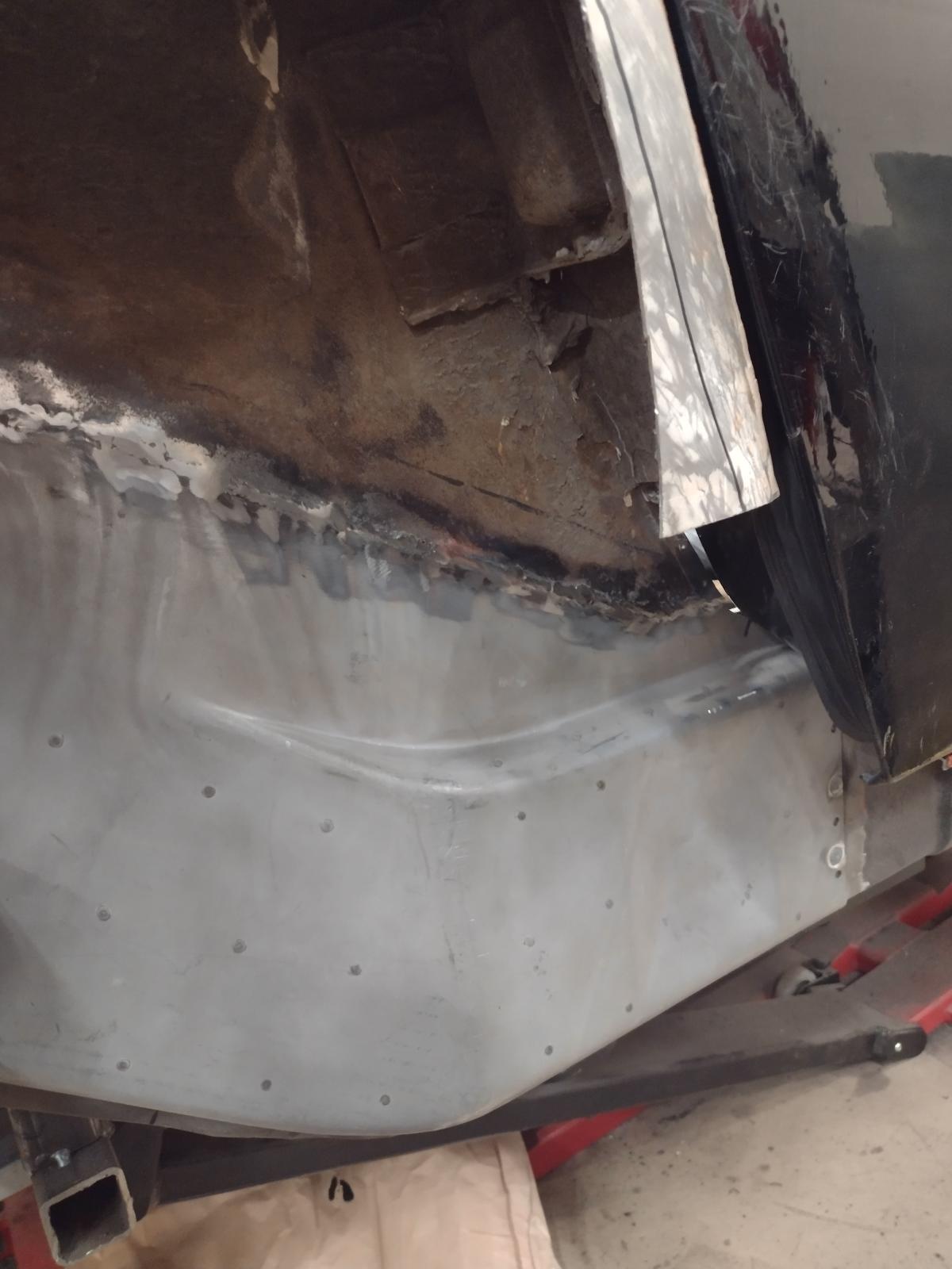
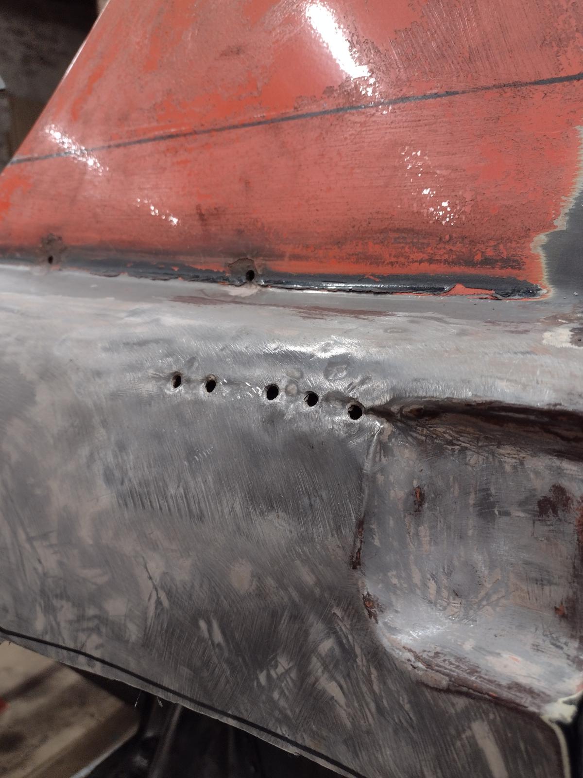
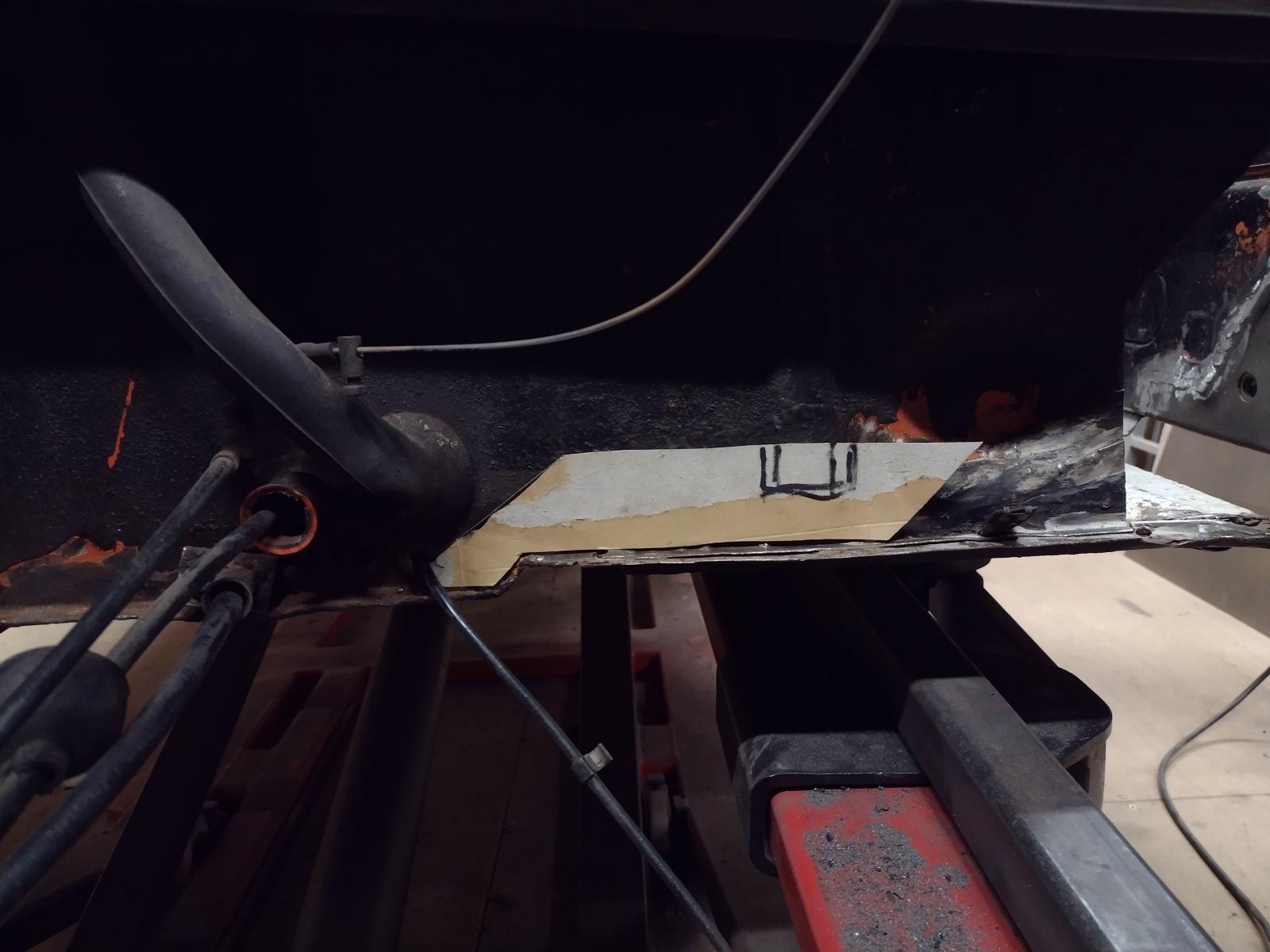
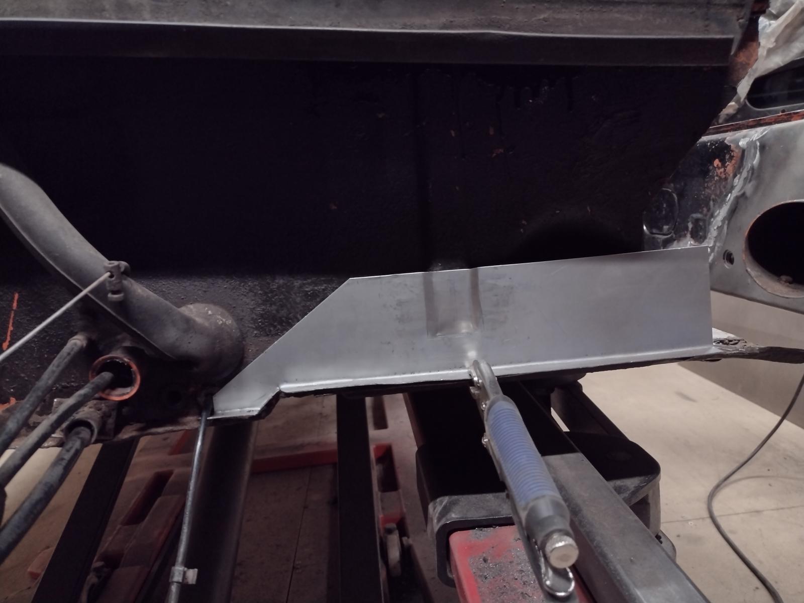
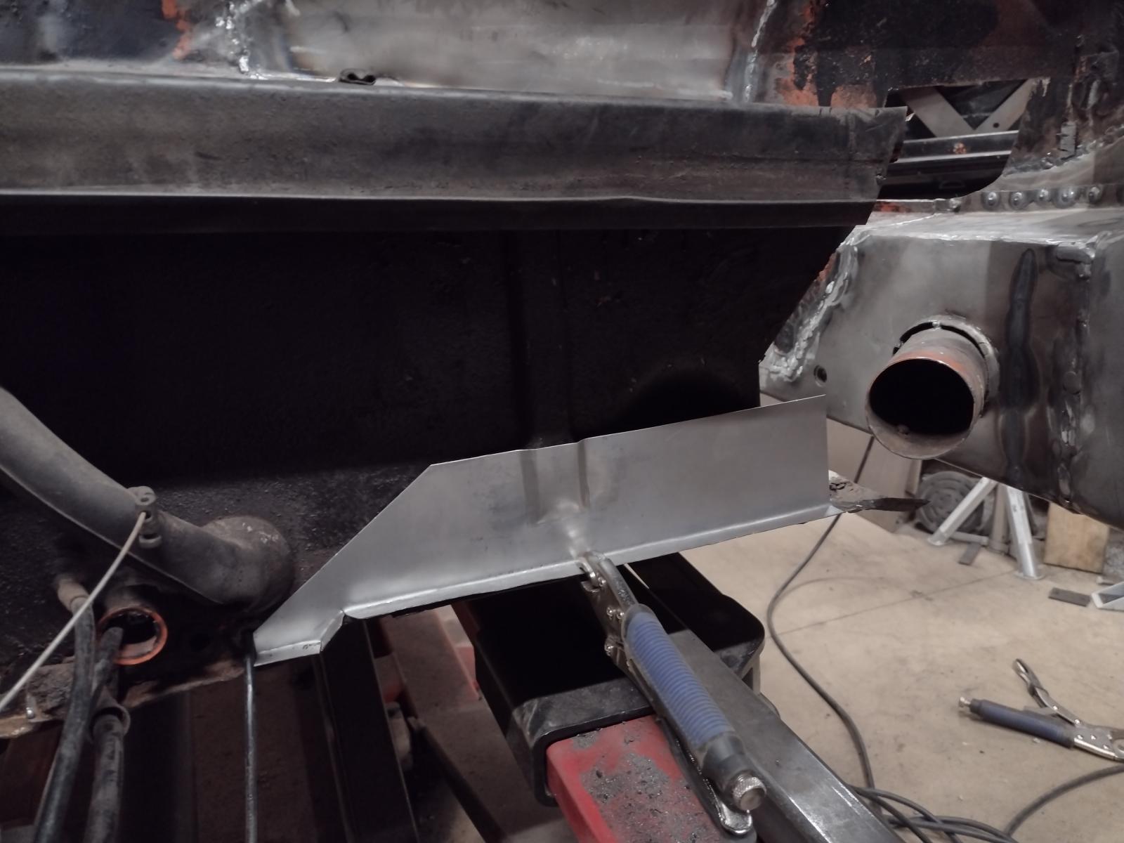
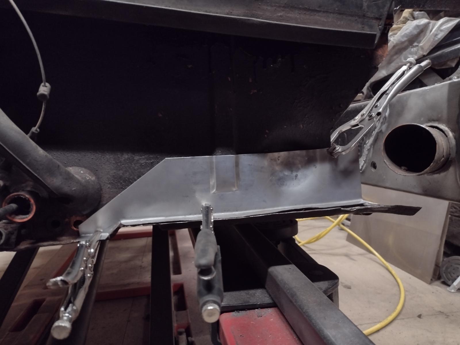
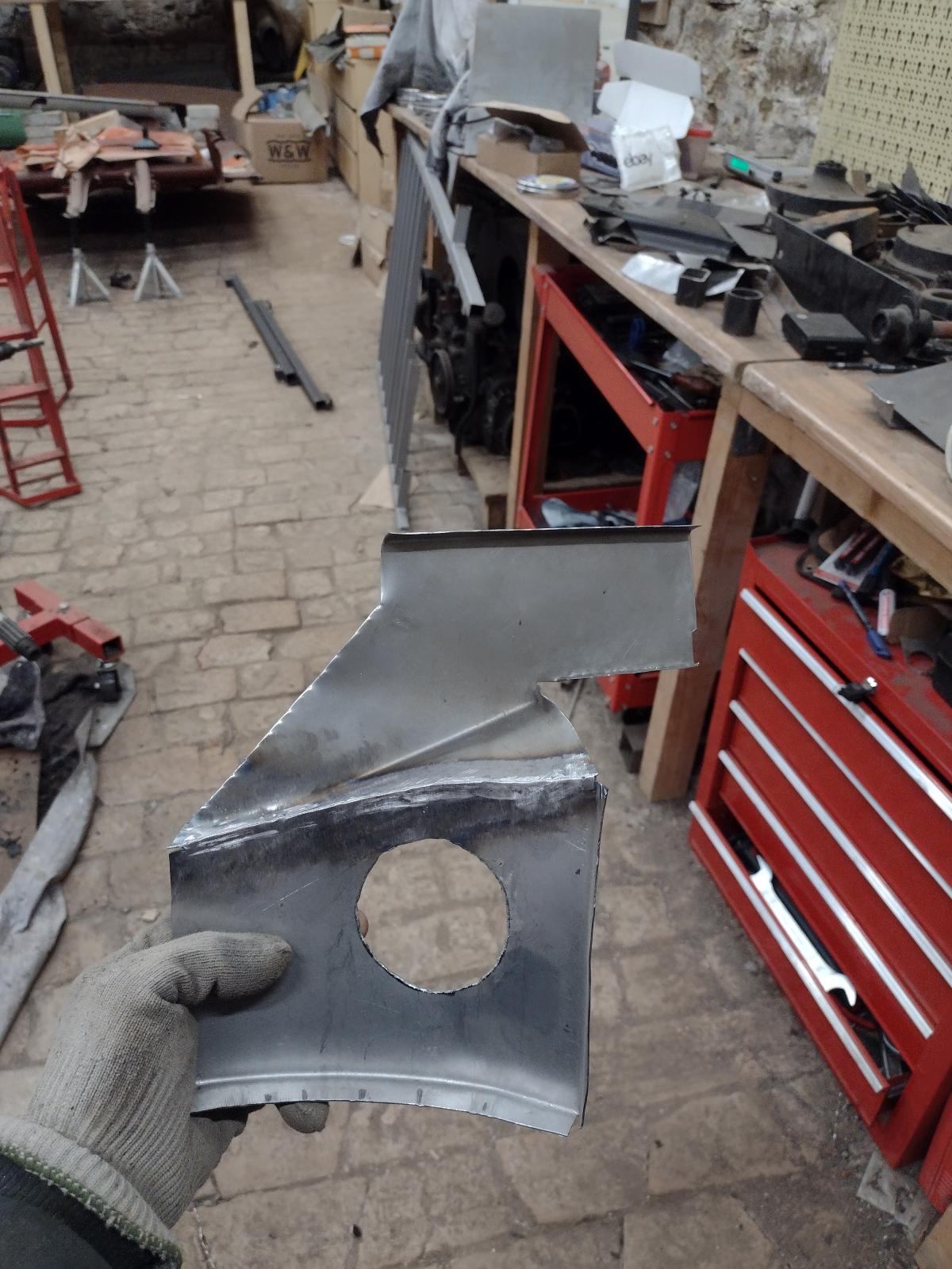
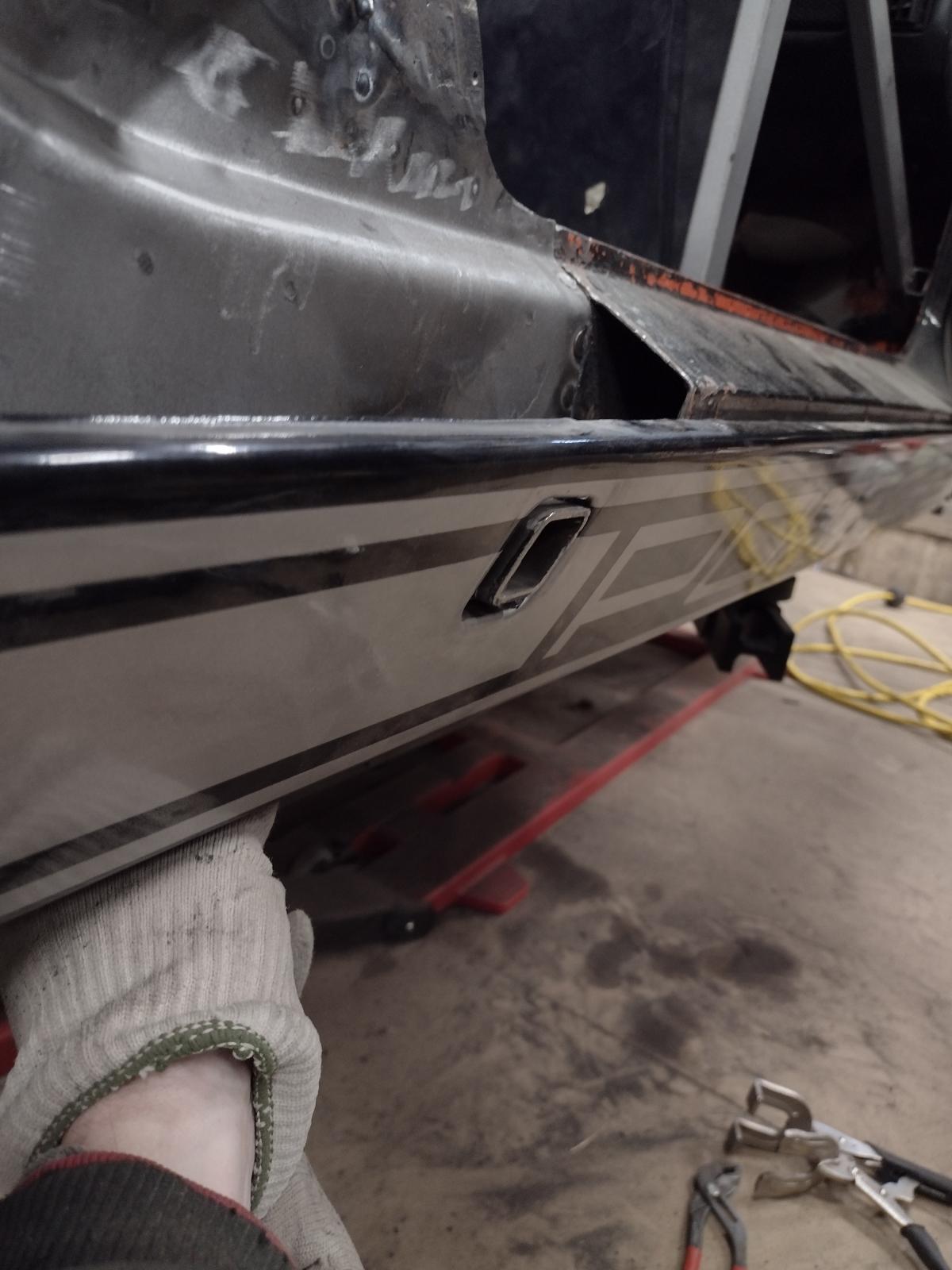
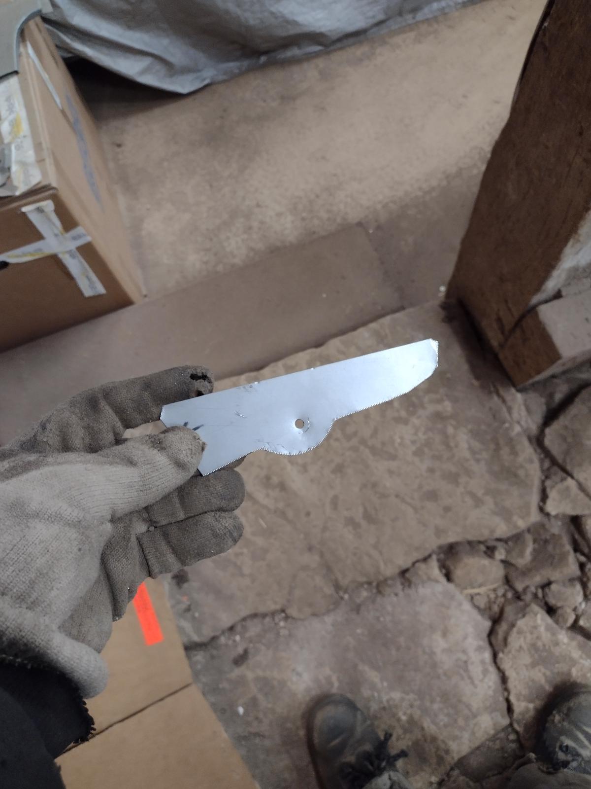
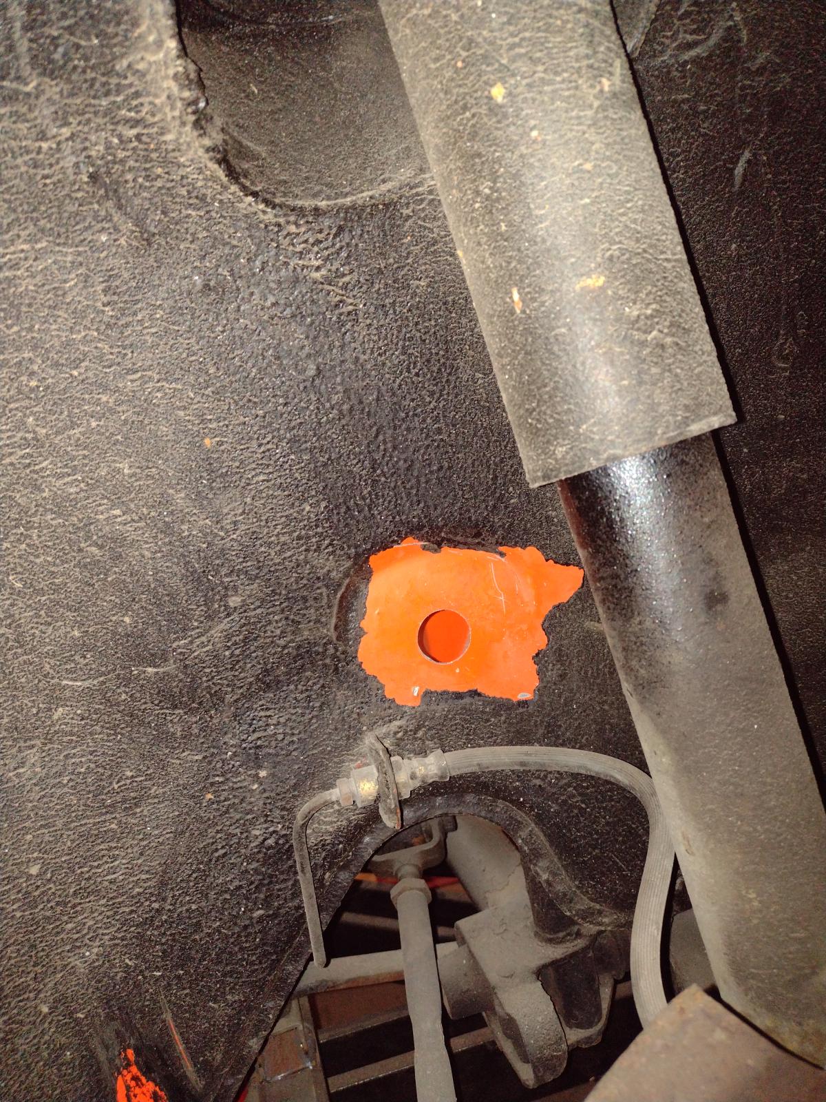
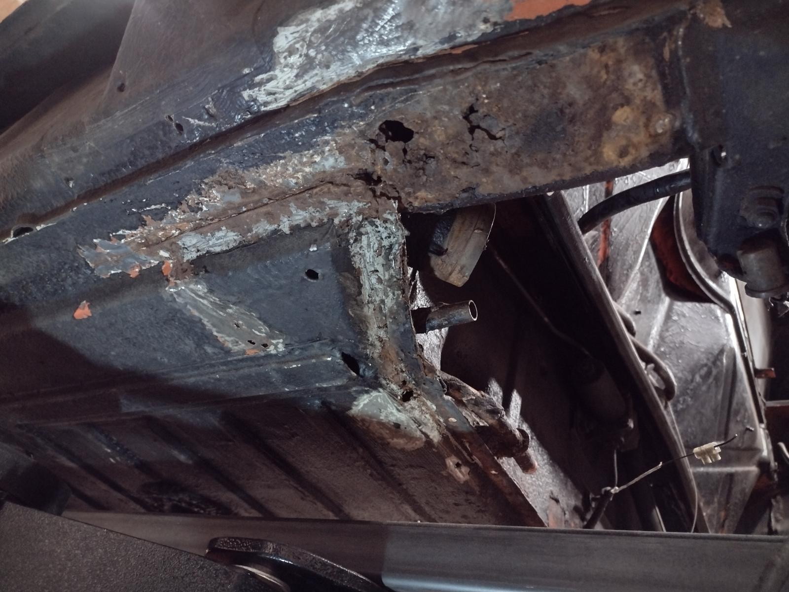
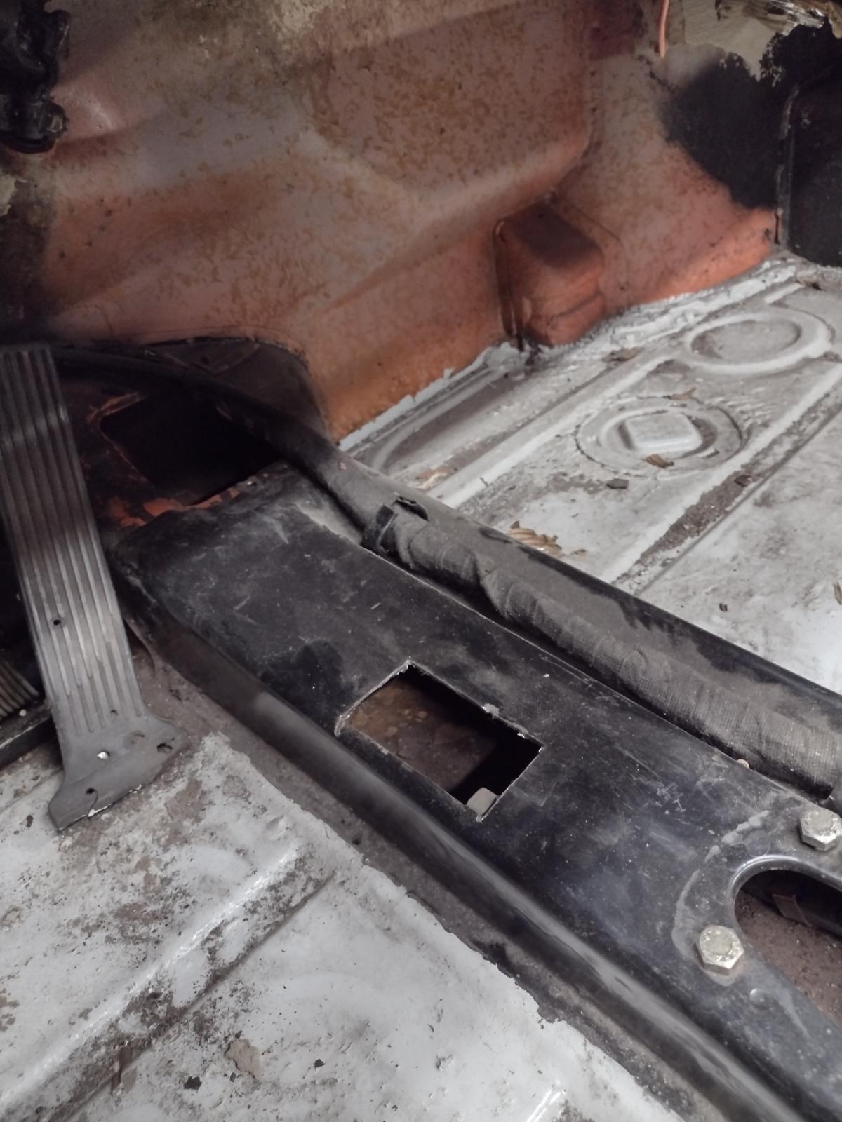
Two questions - I'm embarking on a similar adventure though a) on a WAY much smaller scale and b) without the facility, equipment or skill to do what you're doing. I've made a template of a patch for a spot at the back of the left side clamshell (see photos).
1. It looks like the metal there is 10 guage, maybe 12 (?). Can you confirm? The shop to do the work will custom fabricate the piece. Also, presume cold-rolled sheet steel? I'm thinking TIG welding but would MIG be sufficient (and quicker e.g. cheaper)?
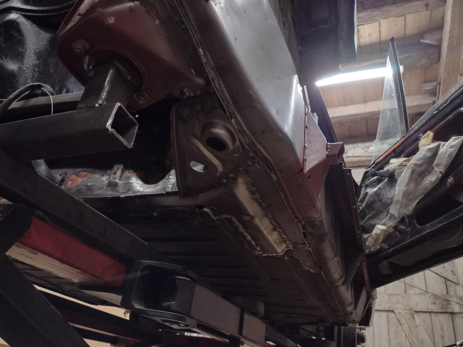
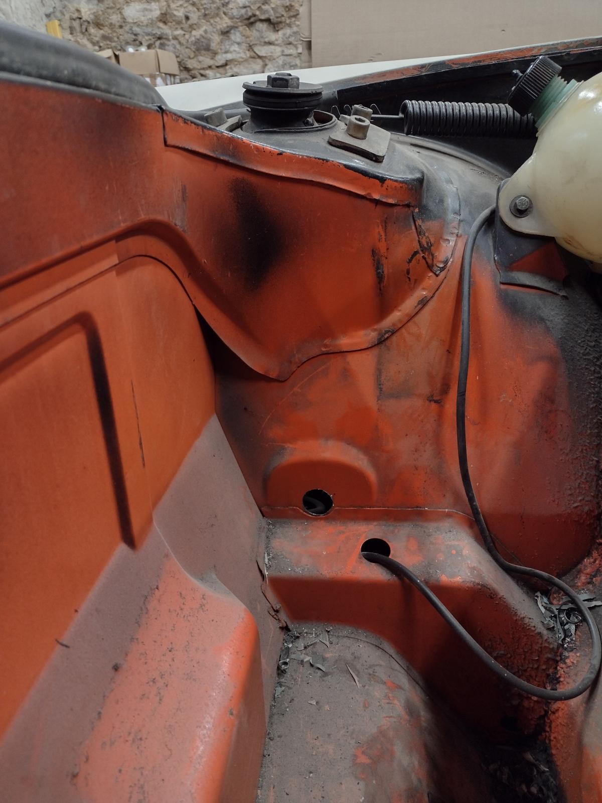
2. The area just forward of the jack triangle might also need a bit of flat sheet, like a corner of the floor pan from your photos?
Thanks ever so much!
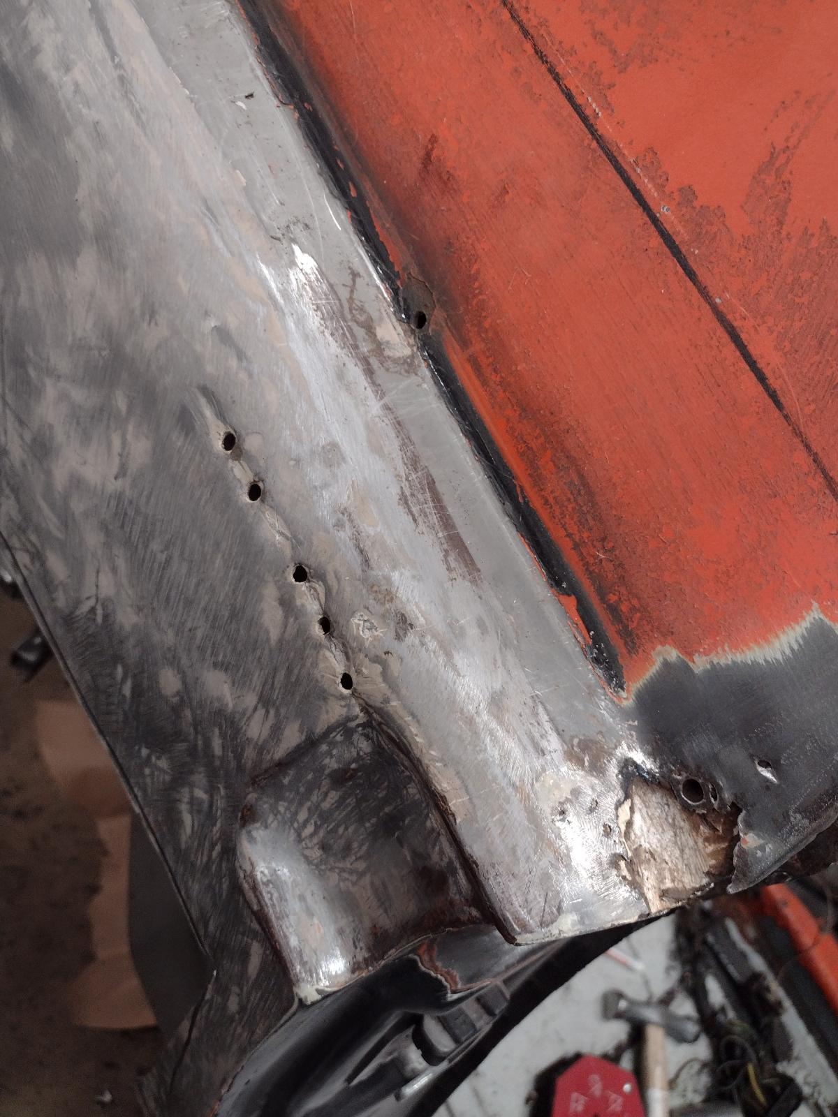
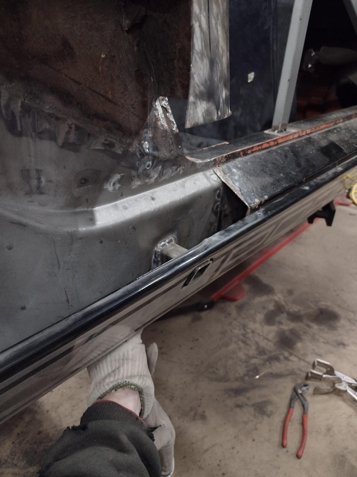
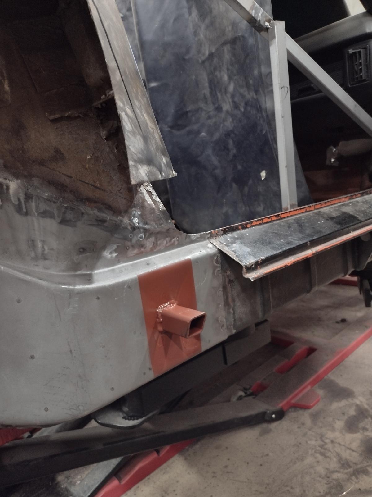
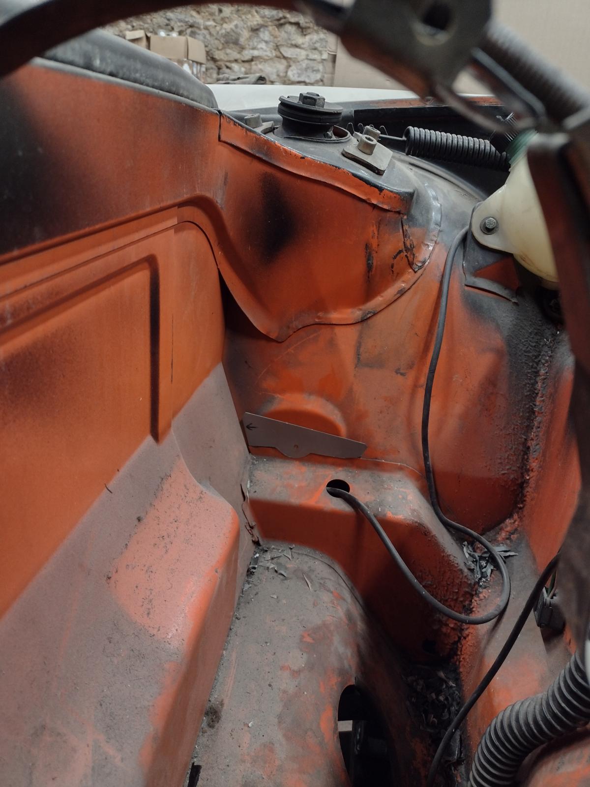
The cancer cut out (very localized - from "the long ago time" of daily driving grit and salt accumulation behind the rocker panel):
Click to view attachment
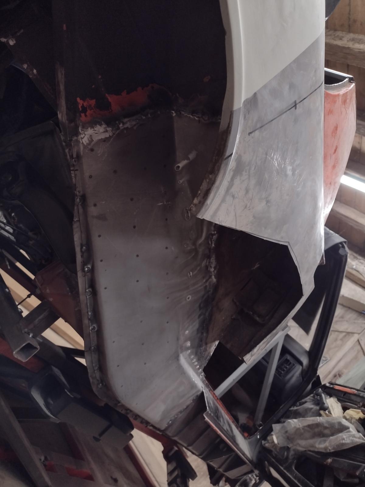
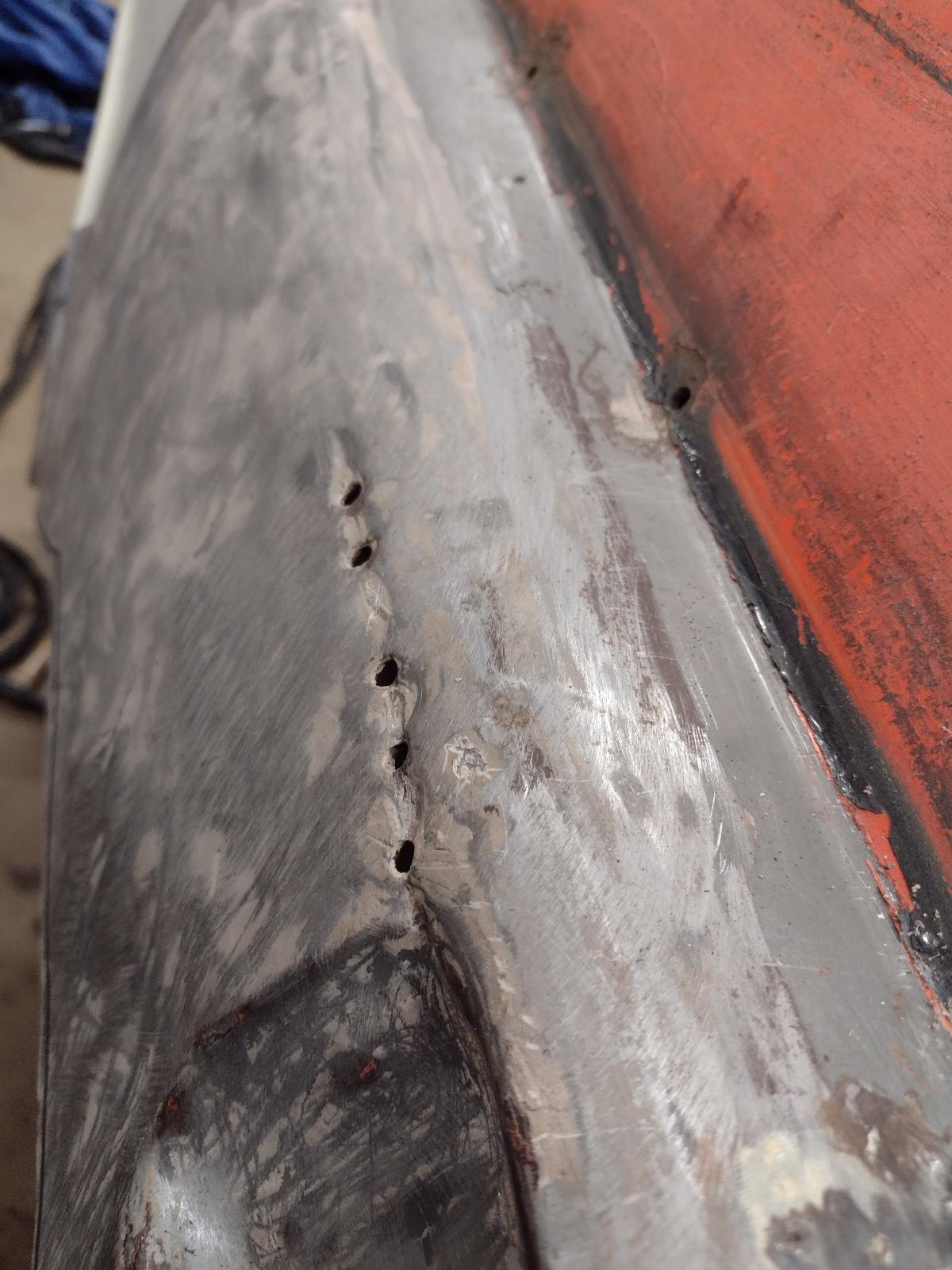
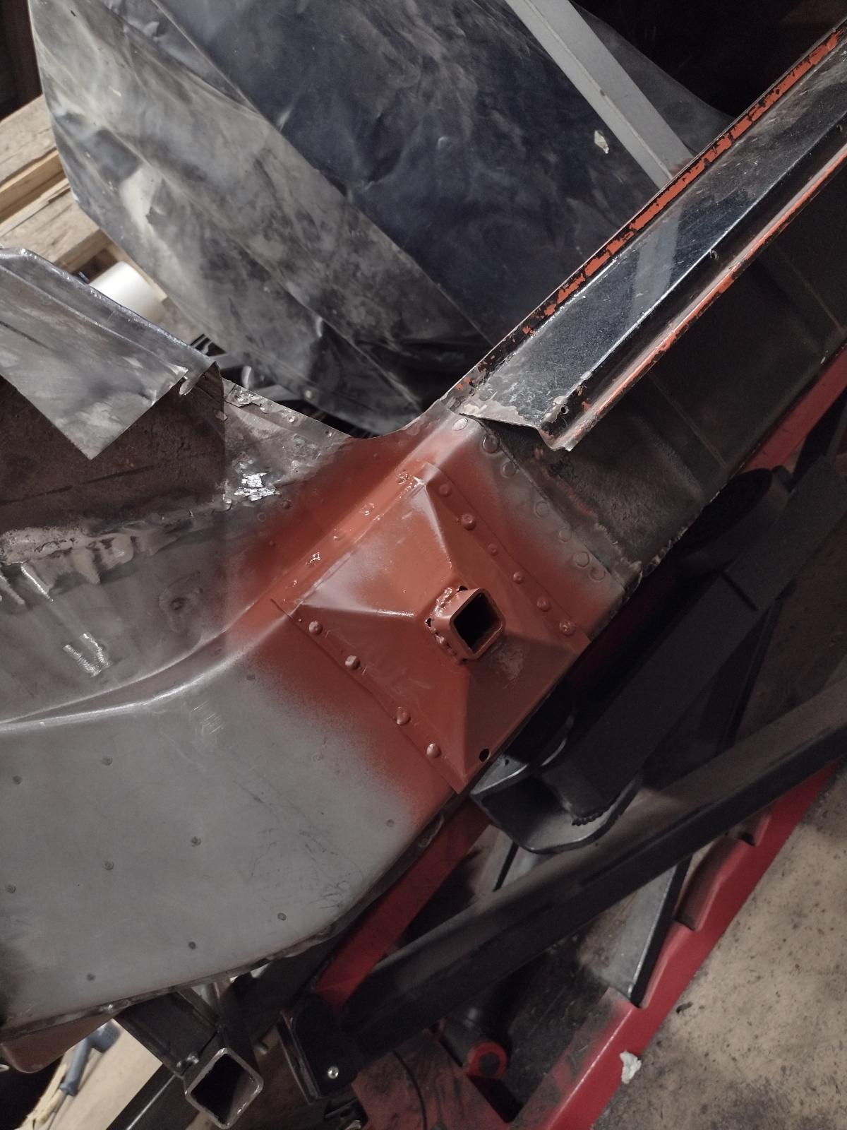
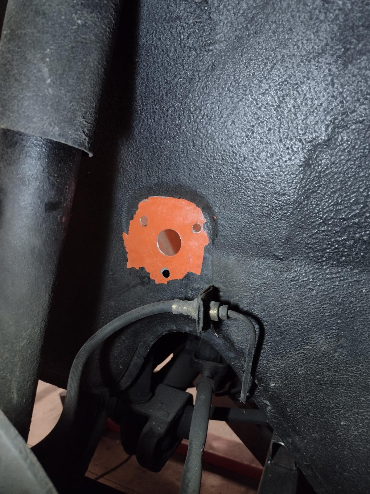
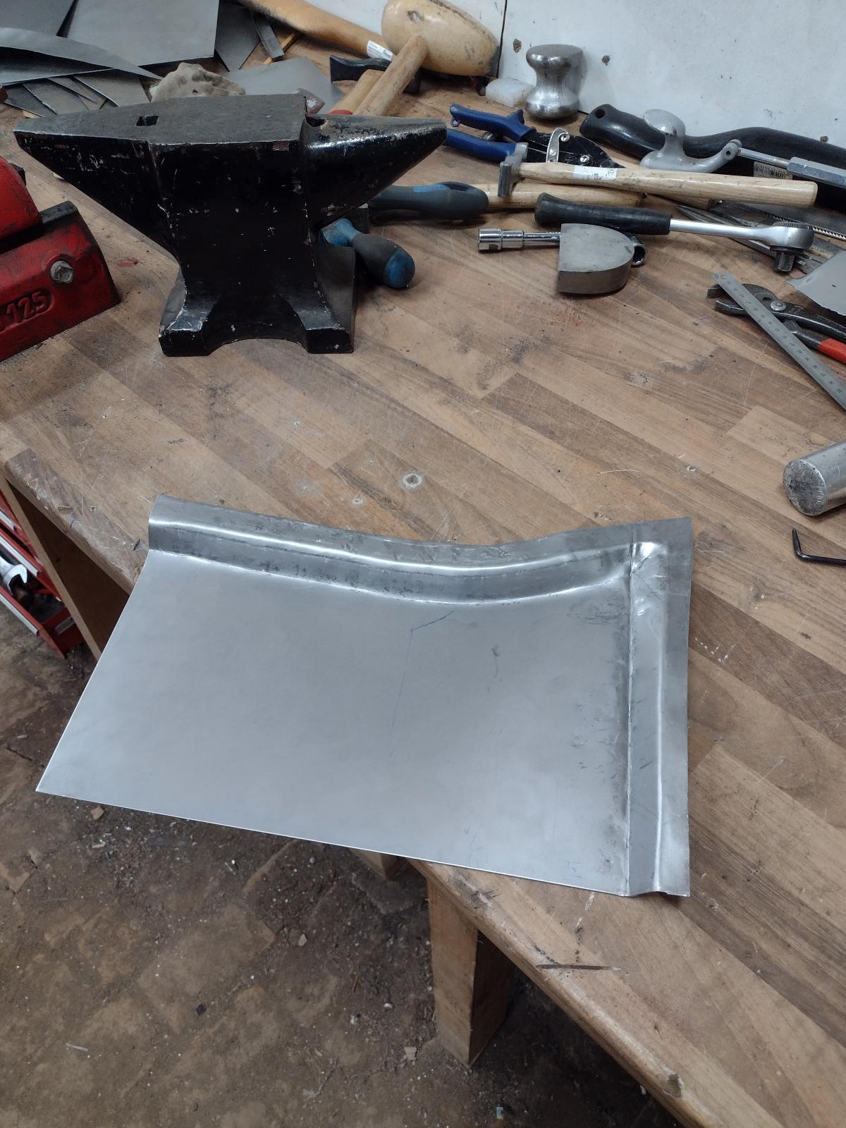
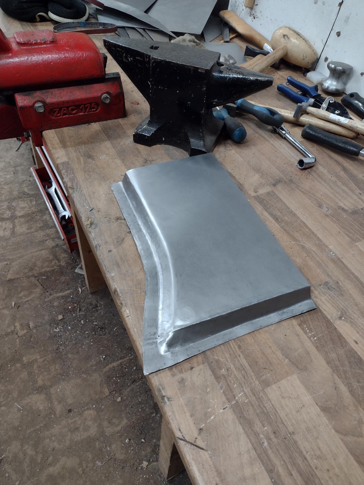
The template mockup:
Click to view attachment
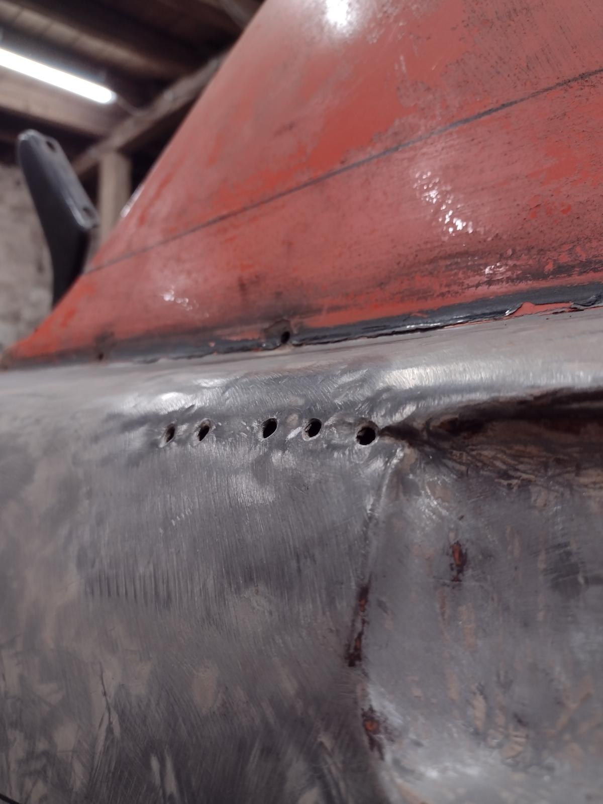
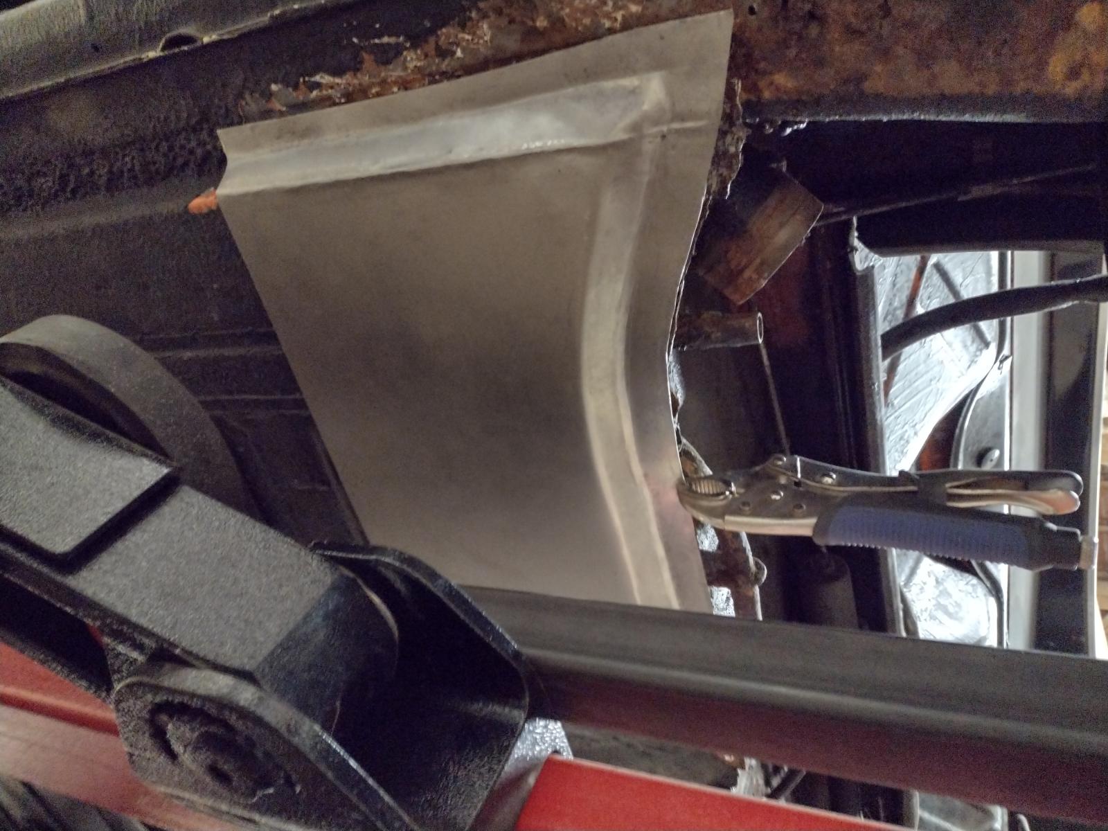
The template in place:
Click to view attachment
Two questions - I'm embarking on a similar adventure though a) on a WAY much smaller scale and b) without the facility, equipment or skill to do what you're doing. I've made a template of a patch for a spot at the back of the left side clamshell (see photos).
1. It looks like the metal there is 10 guage, maybe 12 (?). Can you confirm? The shop to do the work will custom fabricate the piece. Also, presume cold-rolled sheet steel? I'm thinking TIG welding but would MIG be sufficient (and quicker e.g. cheaper)?
2. The area just forward of the jack triangle might also need a bit of flat sheet, like a corner of the floor pan from your photos?
Thanks ever so much!
The cancer cut out (very localized - from "the long ago time" of daily driving grit and salt accumulation behind the rocker panel):
Click to view attachment
The template mockup:
Click to view attachment
The template in place:
Click to view attachment
Thanks a lot guys !!
@StarBear : thanks so much for the kind words!
I try to answer:
1)not 100% sure..Il used 12 gauge MIG is also perfectly fine, as long as the welder knows what he does. Il used both. Usually TIG where I have an access behind to planish, MIG where not.
2)the area you mean is (if I see well) both a bit of the floor and a part of the long. Maybe you can see it better on the other side ? Otherwise if you wait a couple weeks I am doing this kind of repair also on the driver's side so I will share the pictures!
Do not hesitate if you have more questions, happy to help!
So… next update!
Now the goal was to close the firewall, so…let’s start!
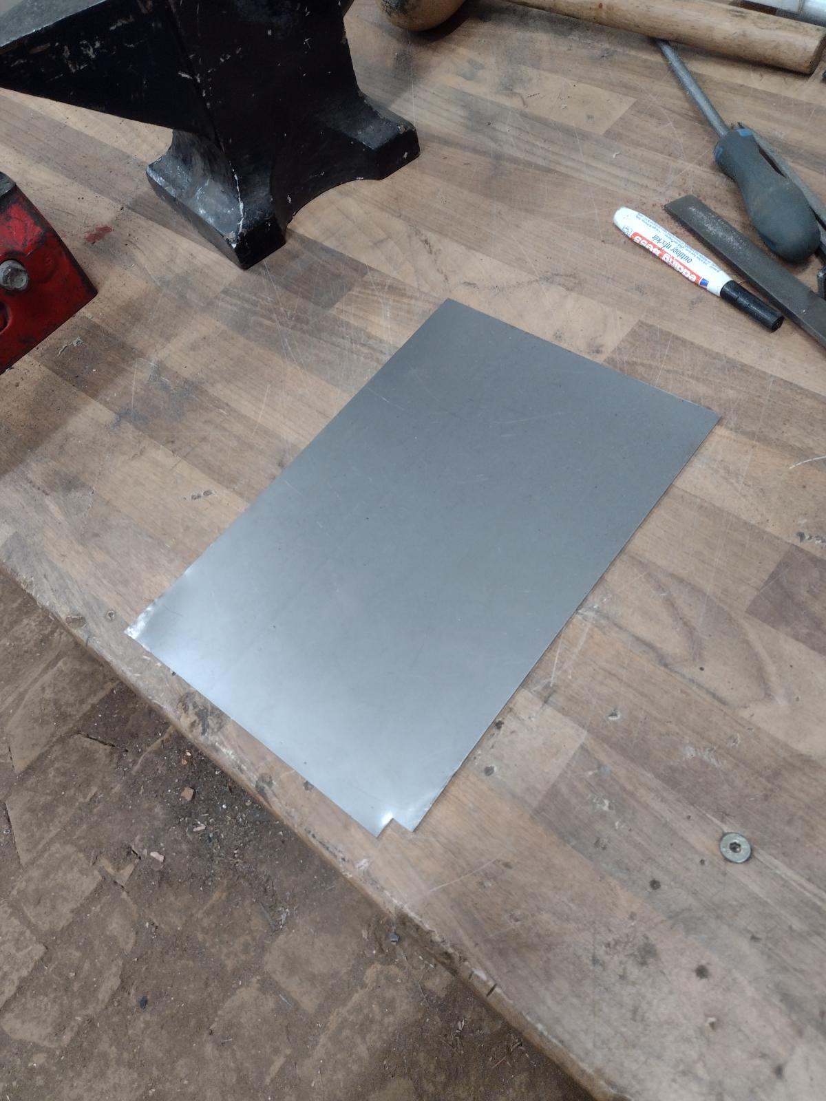
Making the part:

You see it coming?

Still some work:


Getting there:
And the top part:


Welded together:
And welded to the car:
Then I made the small part left on top of it:
Welded:
And some rust protection, paint,…
And the passenger side-firewall is done:
Then the jack point:
Here adjusting:
Rust protection:
And complete:
Under it the donut triangle is also back there:
I still have more to share, stay tuned!
Antoine
@StarBear : thanks so much for the kind words!
I try to answer:
1)not 100% sure..Il used 12 gauge
MIG is also perfectly fine, as long as the welder knows what he does. Il used both. Usually TIG where I have an access behind to planish, MIG where not.2)the area you mean is (if I see well) both a bit of the floor and a part of the long. Maybe you can see it better on the other side ? Otherwise if you wait a couple weeks I am doing this kind of repair also on the driver's side so I will share the pictures!
Do not hesitate if you have more questions, happy to help!
So… next update!
Now the goal was to close the firewall, so…let’s start!
Making the part:
You see it coming?
Still some work:
Getting there:
And the top part:
Welded together:
And welded to the car:
Then I made the small part left on top of it:
Welded:
And some rust protection, paint,…
And the passenger side-firewall is done:
Then the jack point:
Here adjusting:
Rust protection:
And complete:
Under it the donut triangle is also back there:
I still have more to share, stay tuned!
Antoine
Thanks a lot guys !!
@StarBear : thanks so much for the kind words!
I try to answer:
1)not 100% sure..Il used 12 gauge MIG is also perfectly fine, as long as the welder knows what he does. Il used both. Usually TIG where I have an access behind to planish, MIG where not.
2)the area you mean is (if I see well) both a bit of the floor and a part of the long. Maybe you can see it better on the other side ? Otherwise if you wait a couple weeks I am doing this kind of repair also on the driver's side so I will share the pictures!
Do not hesitate if you have more questions, happy to help!
So… next update!
Now the goal was to close the firewall, so…let’s start!
Making the part:
You see it coming?
Still some work:
Getting there:

And the top part:
Welded together:


And welded to the car:

Then I made the small part left on top of it:
Welded:

And some rust protection, paint,…
And the passenger side-firewall is done:

Then the jack point:
Here adjusting:
Rust protection:
And complete:
Under it the donut triangle is also back there:
I still have more to share, stay tuned!
Antoine
@StarBear : thanks so much for the kind words!
I try to answer:
1)not 100% sure..Il used 12 gauge
MIG is also perfectly fine, as long as the welder knows what he does. Il used both. Usually TIG where I have an access behind to planish, MIG where not.2)the area you mean is (if I see well) both a bit of the floor and a part of the long. Maybe you can see it better on the other side ? Otherwise if you wait a couple weeks I am doing this kind of repair also on the driver's side so I will share the pictures!
Do not hesitate if you have more questions, happy to help!
So… next update!
Now the goal was to close the firewall, so…let’s start!
Making the part:
You see it coming?
Still some work:
Getting there:
And the top part:
Welded together:
And welded to the car:
Then I made the small part left on top of it:
Welded:
And some rust protection, paint,…
And the passenger side-firewall is done:
Then the jack point:
Here adjusting:
Rust protection:
And complete:
Under it the donut triangle is also back there:
I still have more to share, stay tuned!
Antoine
So cool to see the inside of 914 areas never would have thought to see.
Really doing a great job, again, thanks for sharing the project and pictures!
Really doing a great job, again, thanks for sharing the project and pictures!
Thanks a lot, really appreciated !
Some more news..
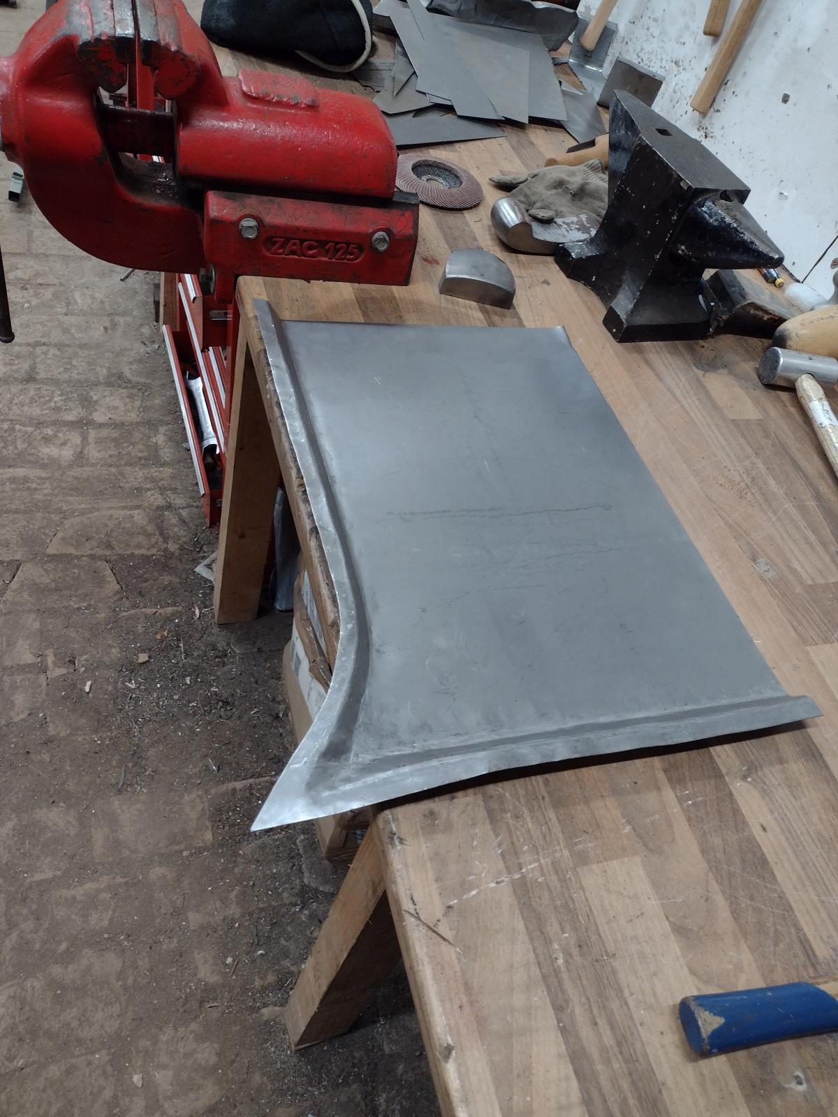
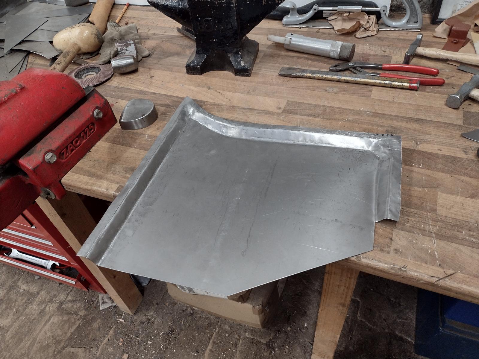
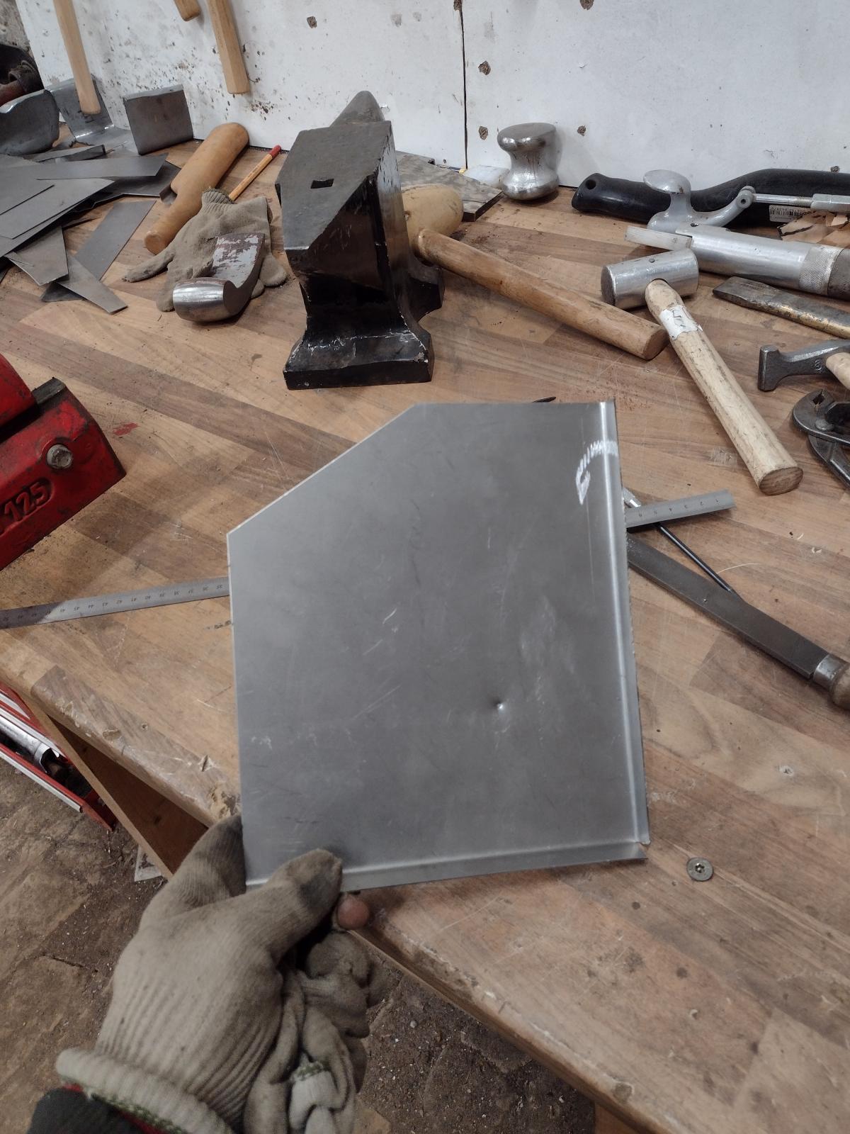
I created this small hammering form:
Guessing why?
Yes, to build myself the engine sealing surrounds:
And my first try is quite positive:
So I will build the long part!
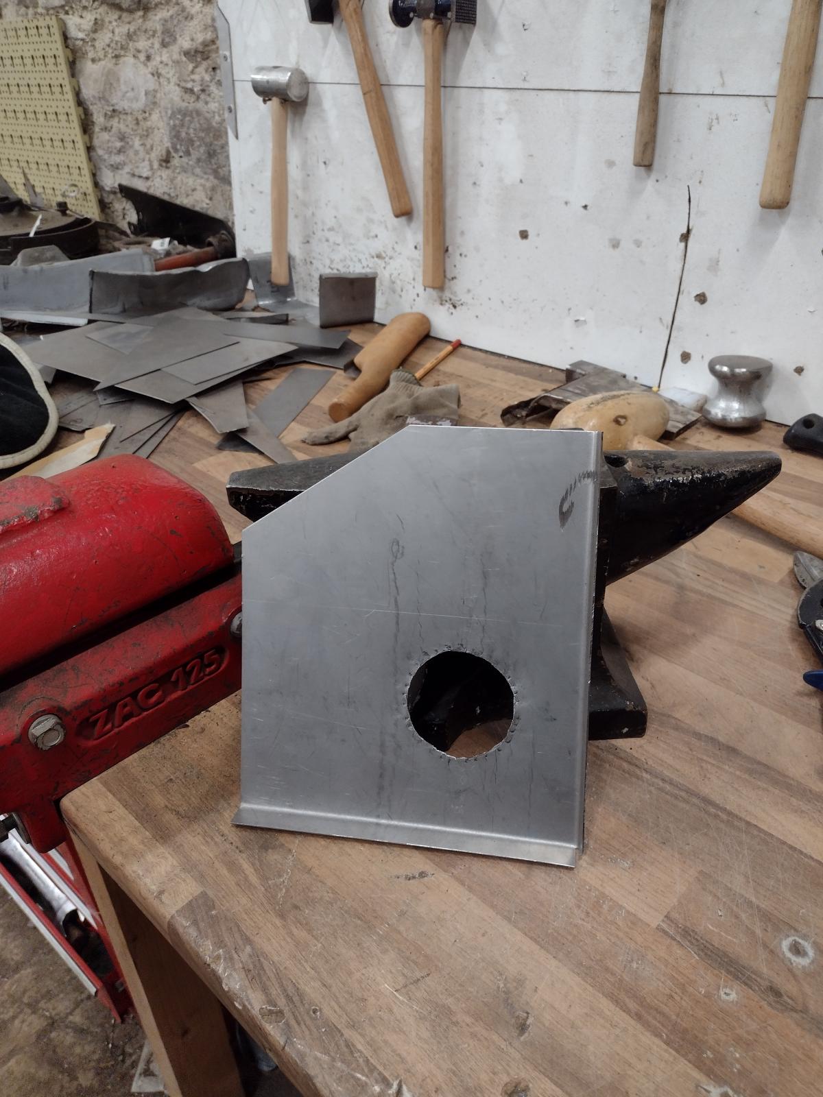
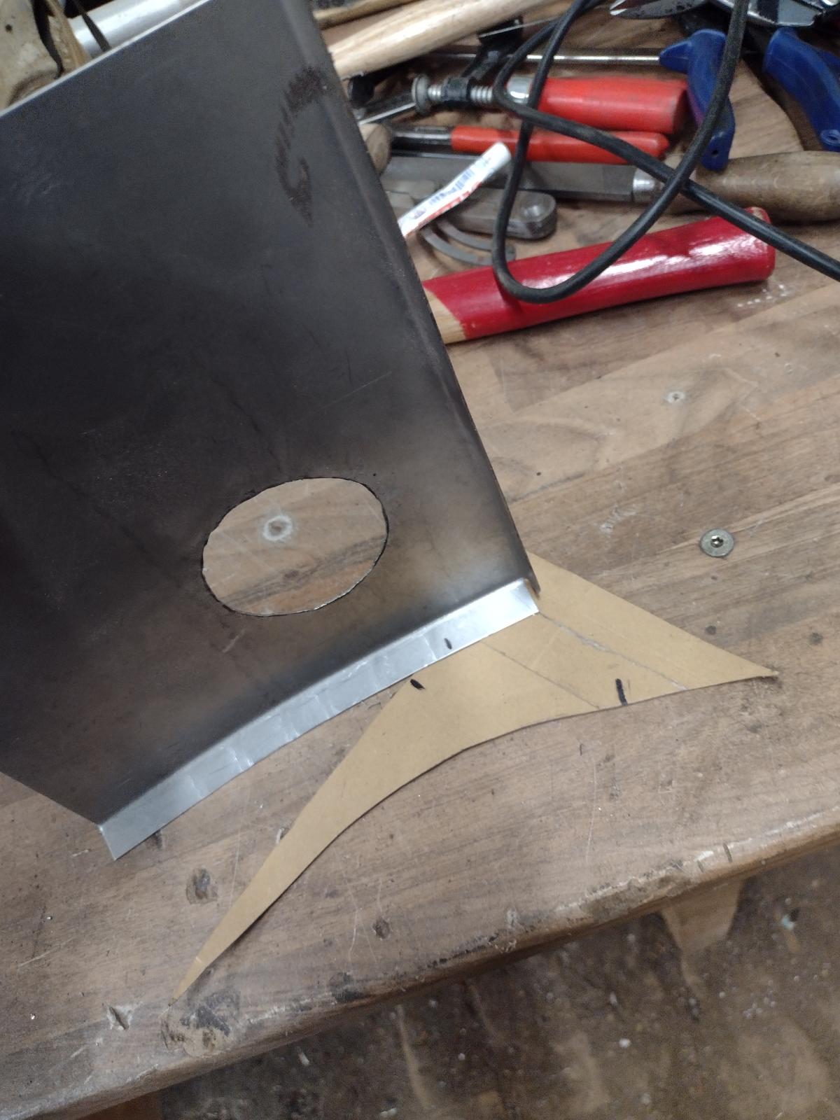
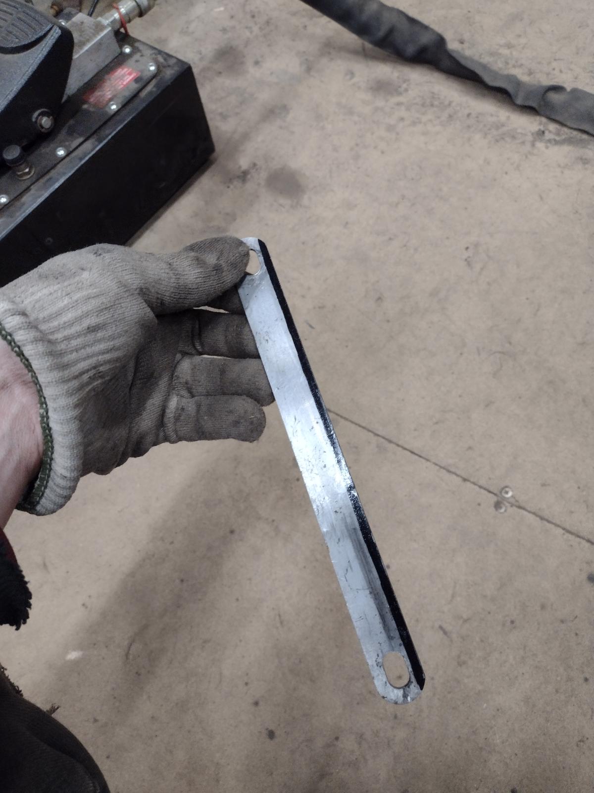
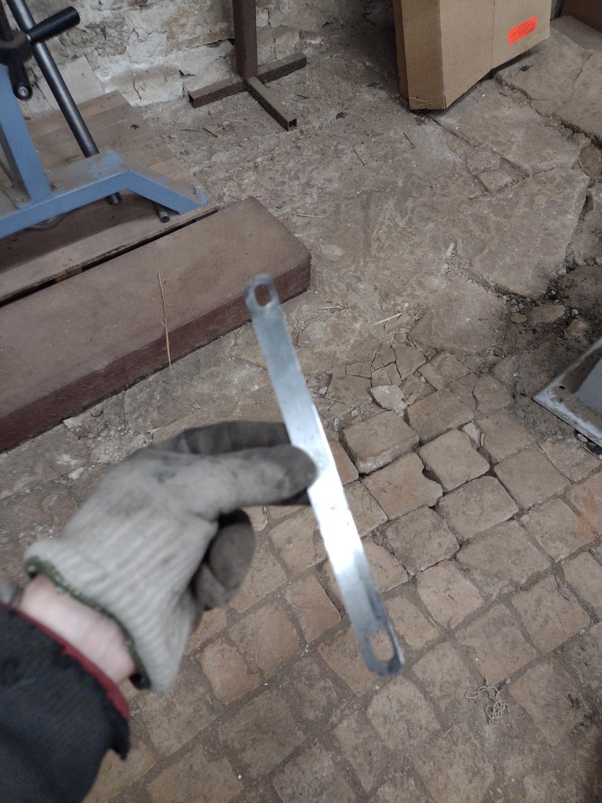
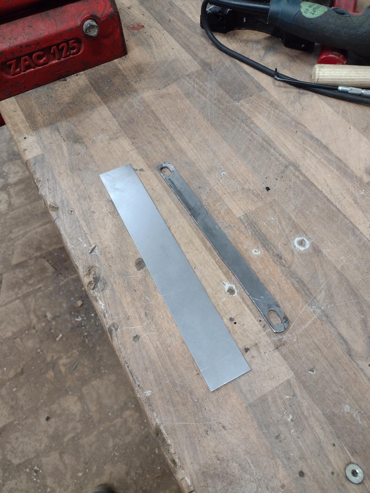
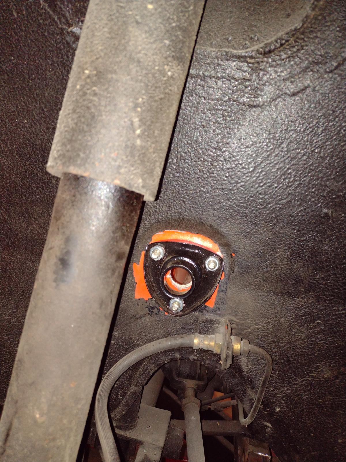
I also mounted my front sway bar, first making a tool to position precisely the hole:
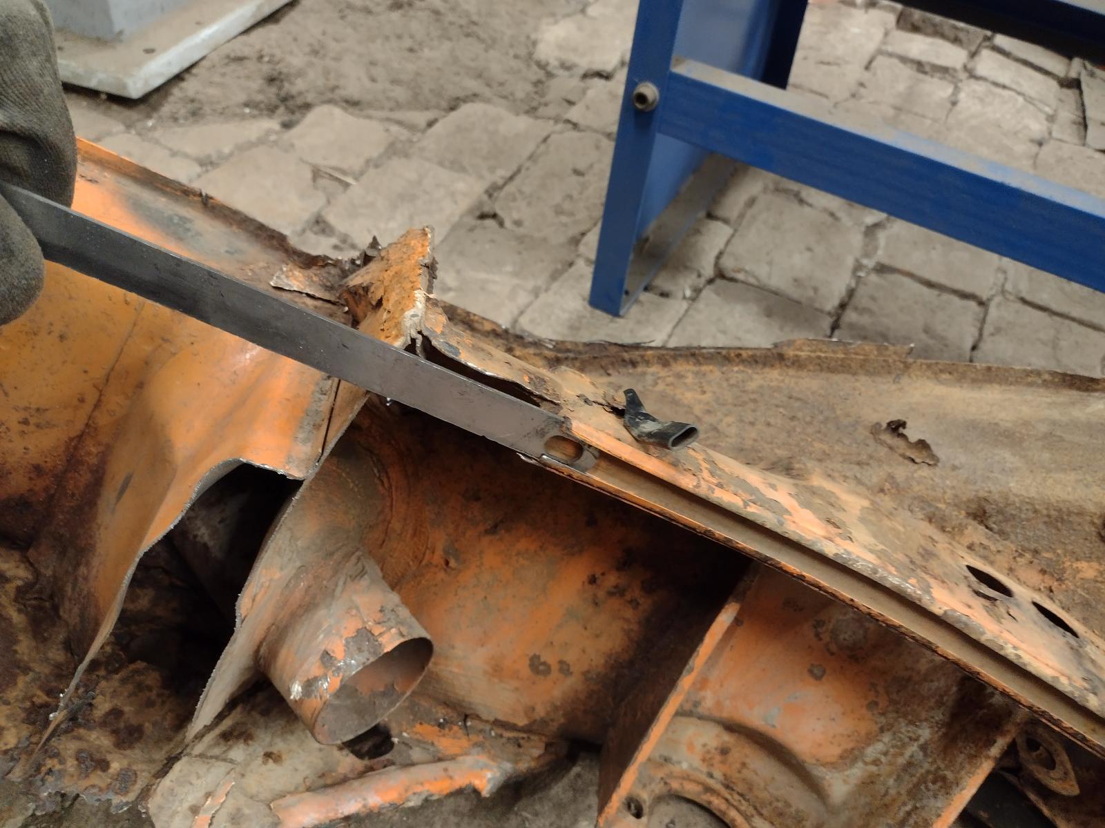
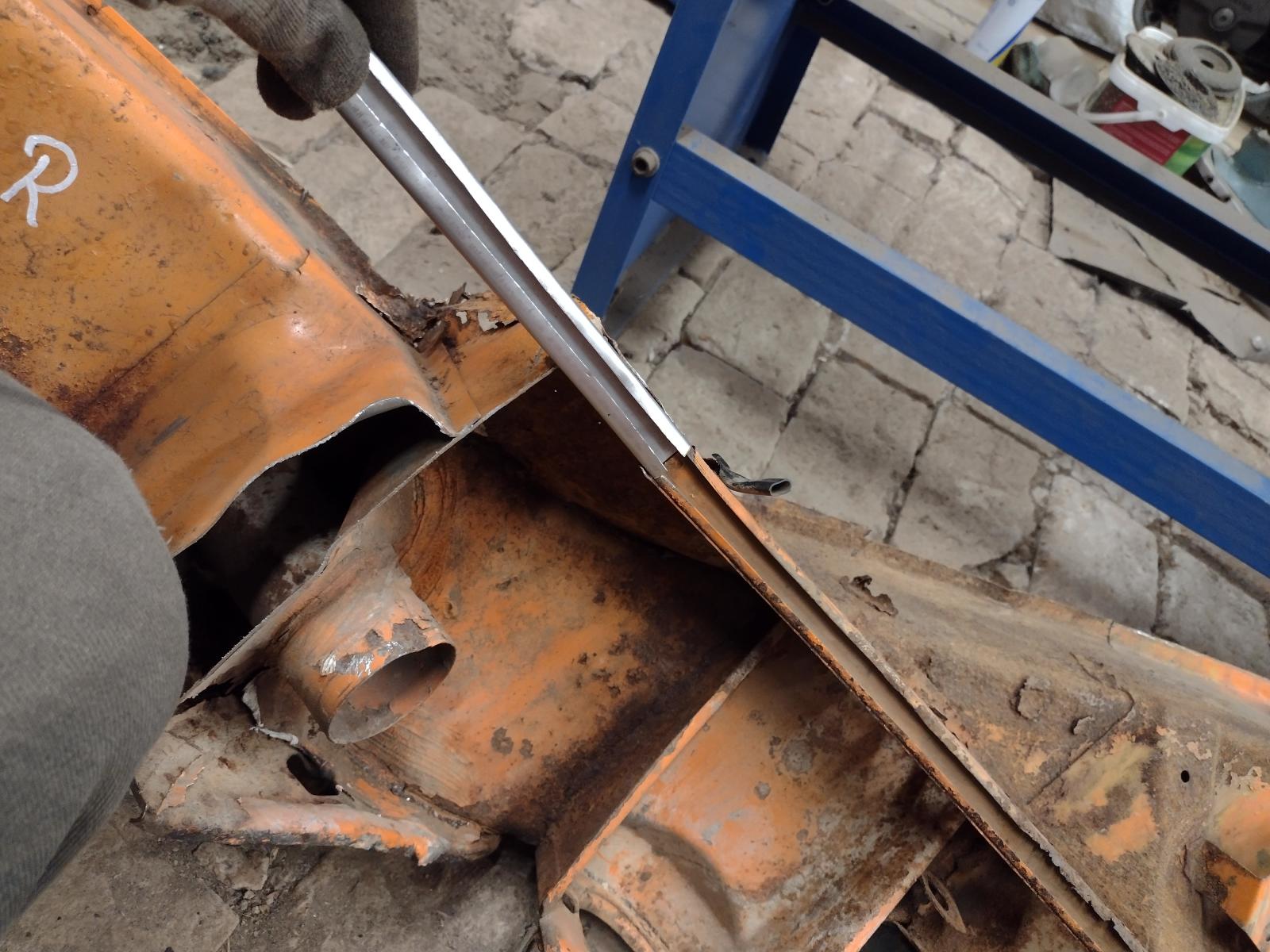
Thema making the holes:
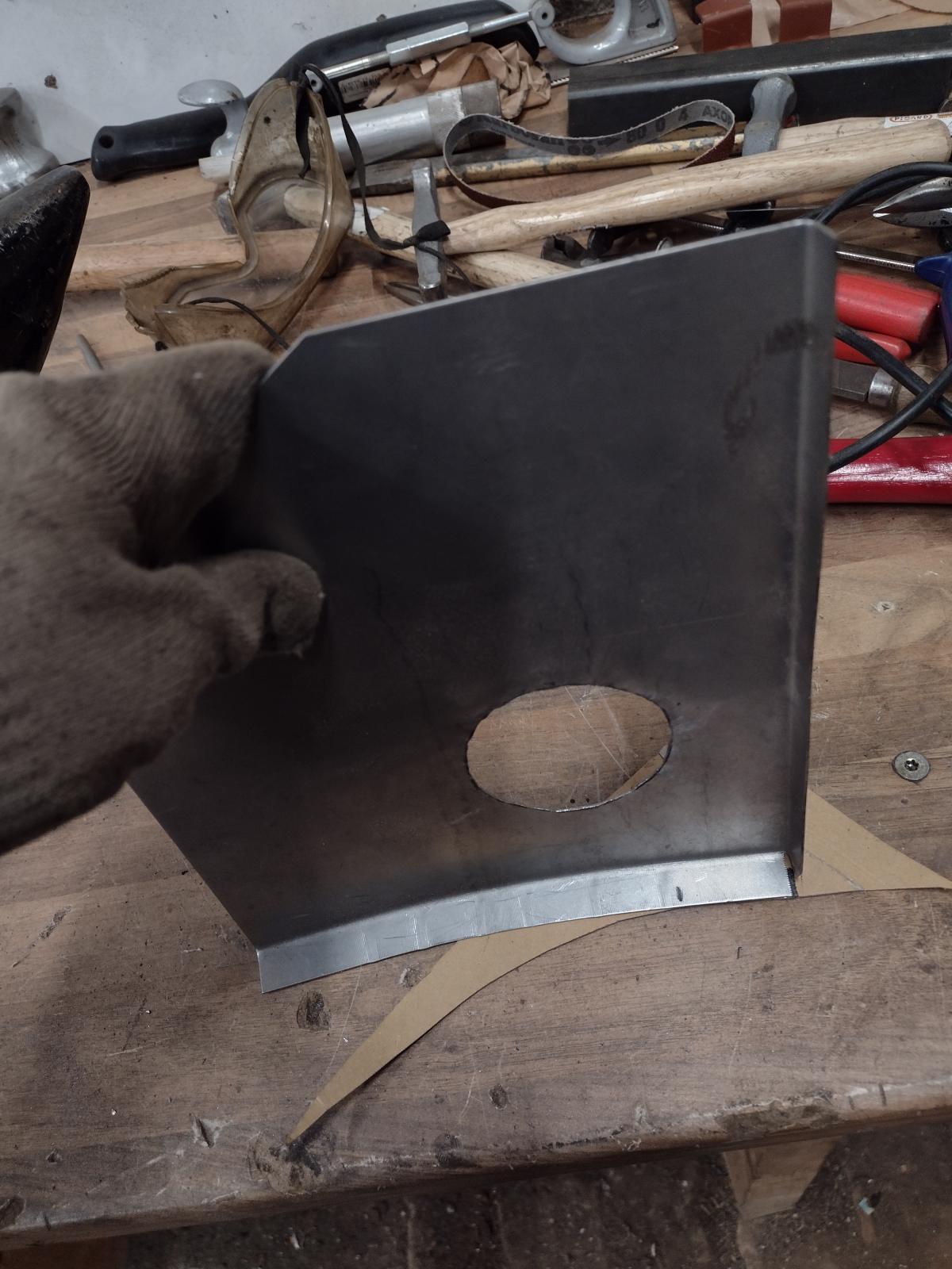
Modifying inside:
And mounting the sway bar mounts :
Welded back the inside frame:
And everything done:
Stay tuned, work on the driver's side is coming!
Antoine
Some more news..
I created this small hammering form:
Guessing why?
Yes, to build myself the engine sealing surrounds:
And my first try is quite positive:
So I will build the long part!
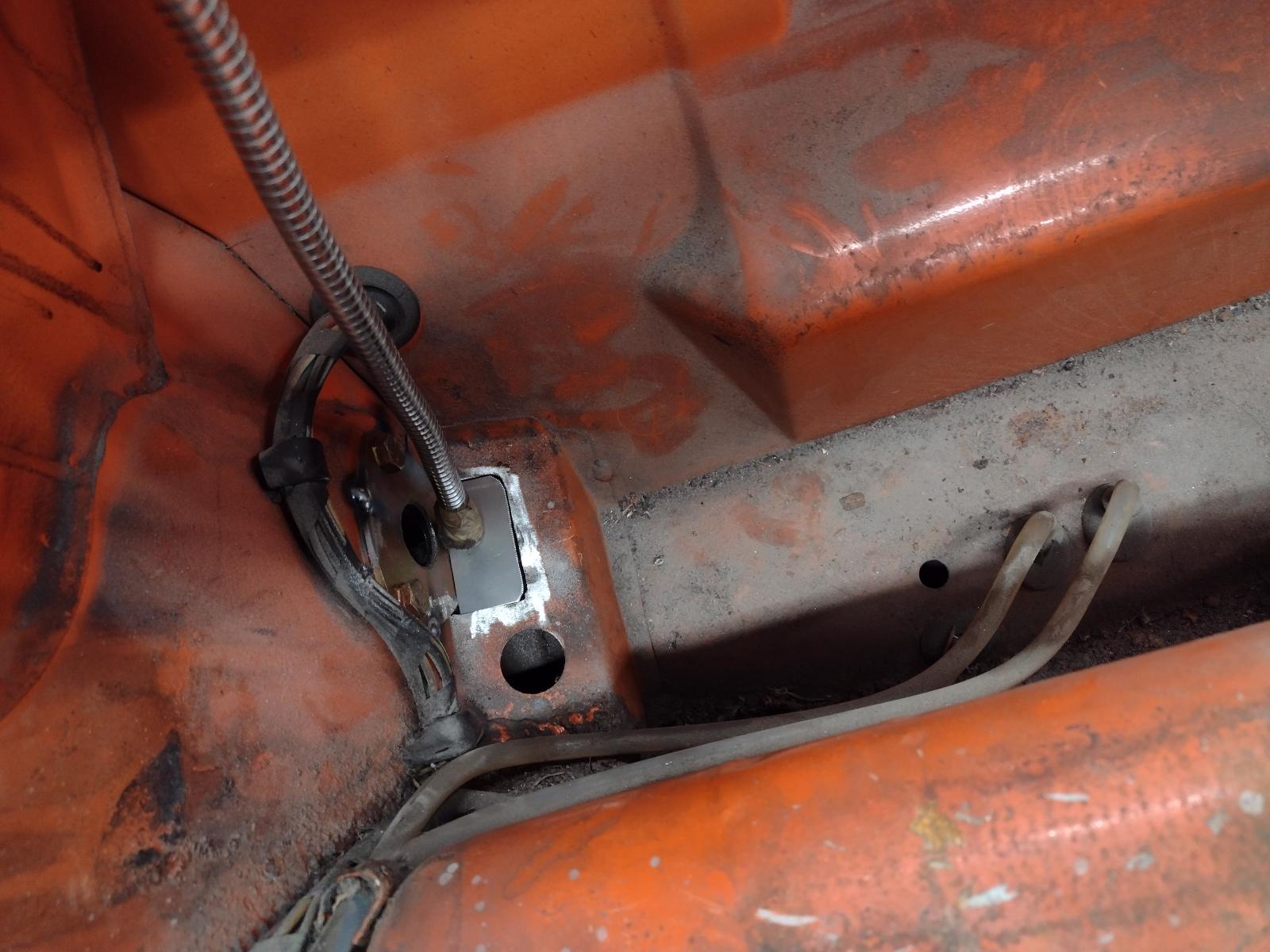
I also mounted my front sway bar, first making a tool to position precisely the hole:
Thema making the holes:
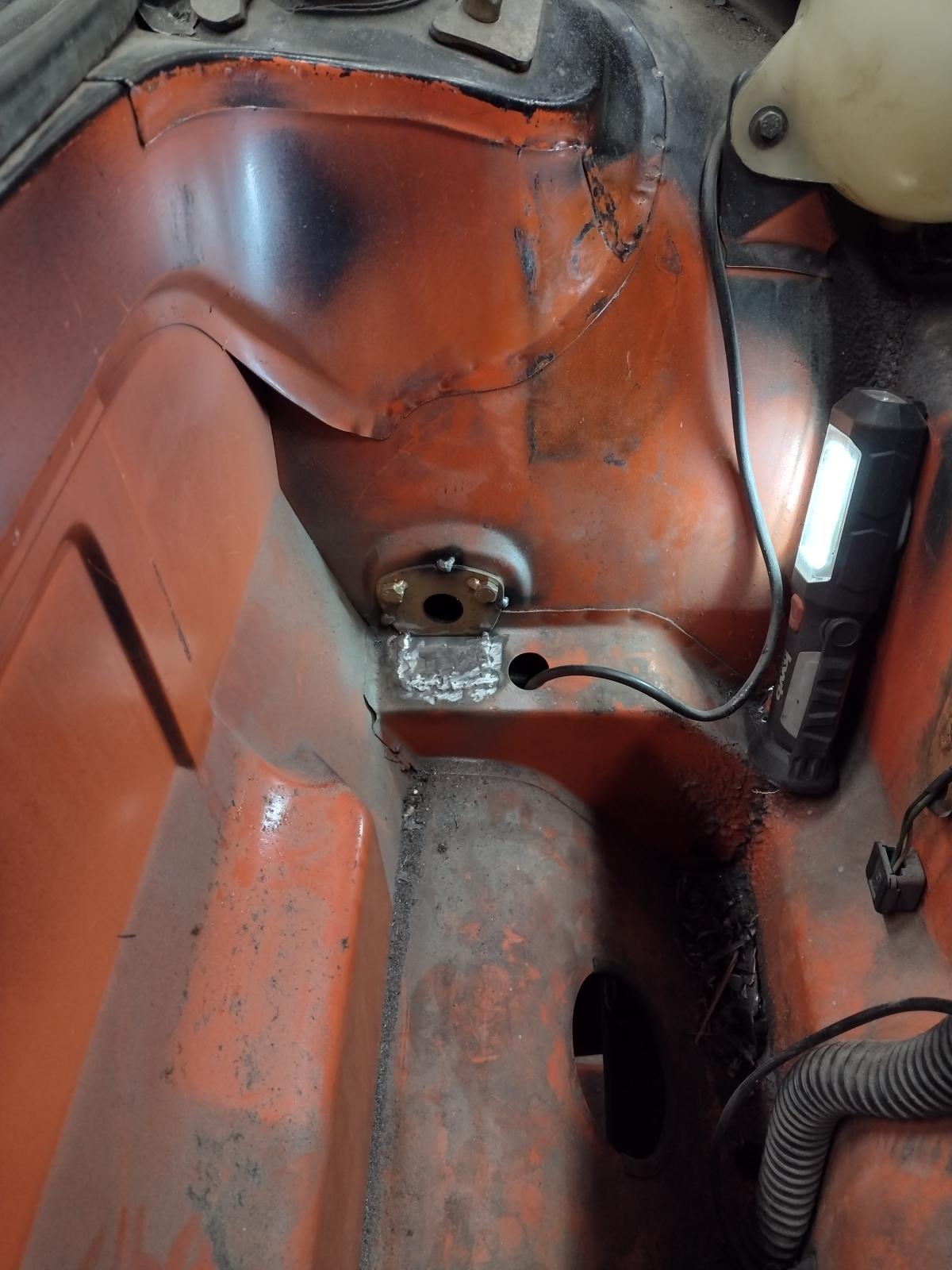
Modifying inside:
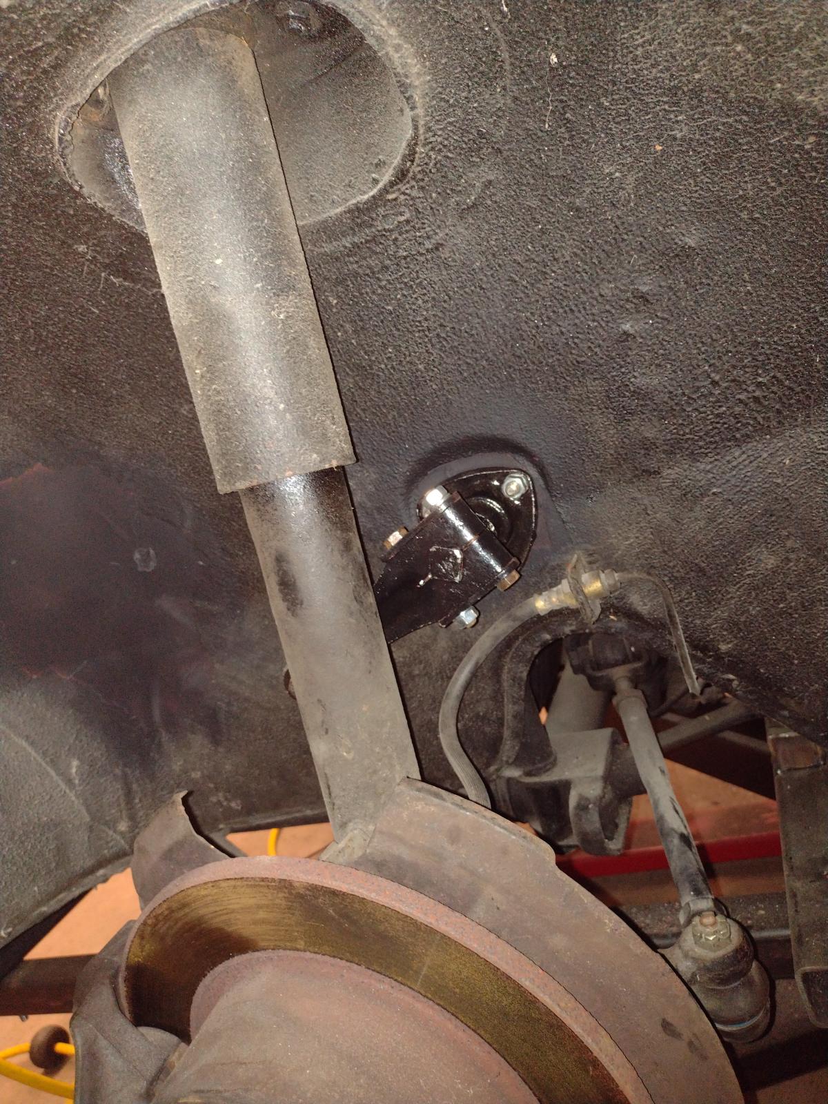
And mounting the sway bar mounts :
Welded back the inside frame:
And everything done:
Stay tuned, work on the driver's side is coming!
Antoine
Awesome work, Antoine! And so many "inside" pictures of the 914. Very valuable.
I remember seeing pictures of the car when you had purchased it. One would never have expected to see such an amount of brown, right?
Don´t forget, the next "Celette" is only 2 hours away from you - if you want to be sure.
Keep on the good work!
Arno
I remember seeing pictures of the car when you had purchased it. One would never have expected to see such an amount of brown, right?
Don´t forget, the next "Celette" is only 2 hours away from you - if you want to be sure.
Keep on the good work!
Arno
double post
QUOTE(Arno914 @ Feb 15 2022, 09:23 AM)
Awesome work, Antoine! And so many "inside" pictures of the 914. Very valuable.
I remember seeing pictures of the car when you had purchased it. One would never have expected to see such an amount of brown, right?
Don´t forget, the next "Celette" is only 2 hours away from you - if you want to be sure.
Keep on the good work!
Arno
Hi Arno
Thanks a lot for the kind words! Sure wasn't expecting that much rust but hopefully I will have some years of driving ahead of me now
Thanks a lot for the offer for the celette, truly appreciated ! Il hope that I won't need it but if Il have any doubt I will come back to you! (Plan is still to only make it solid again, if I was to completely restore it (or a future one!), I will be doing it on your celette for sure!)
Grüße
Antoine
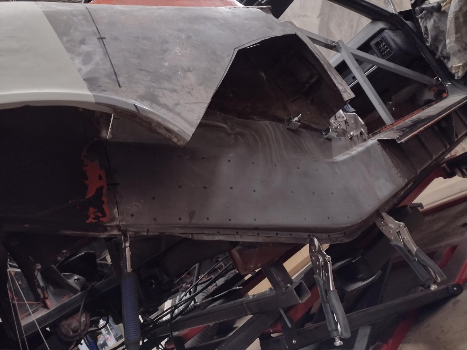
So, as promised, the work on the driver's side!
After a bit of Paint/gravel protection removal, it wasn't looking promising:
And not much better without the jack point triangle :
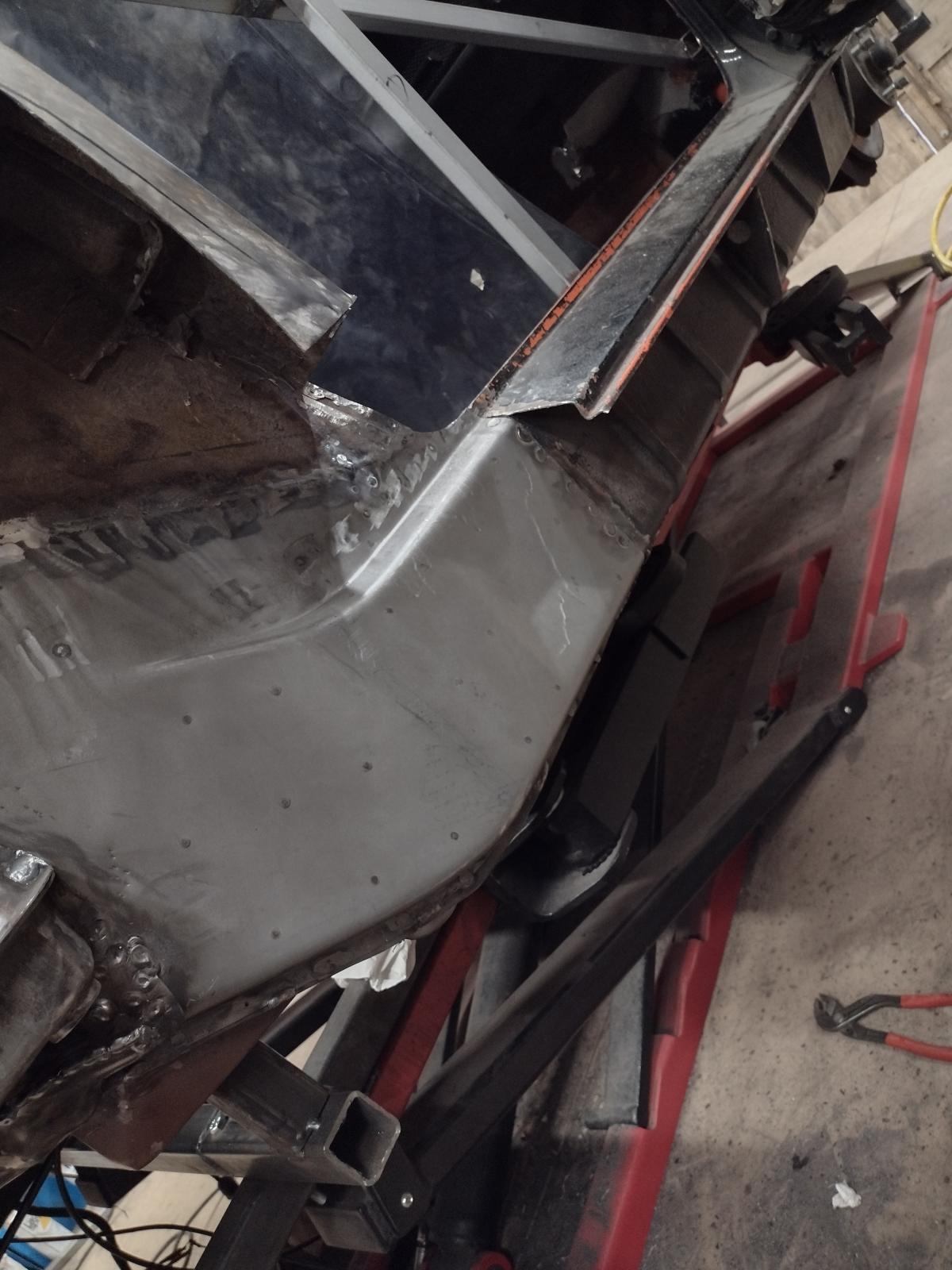
So I prepared the floor pan:
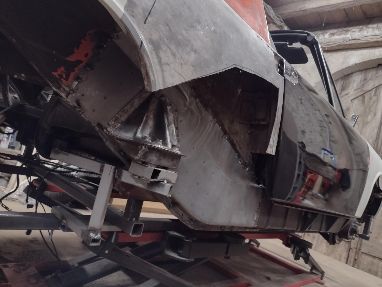
And made some cut:
Now I could see the damages better:
So I made a template :
And the part, from cutting to adjusting to welded:
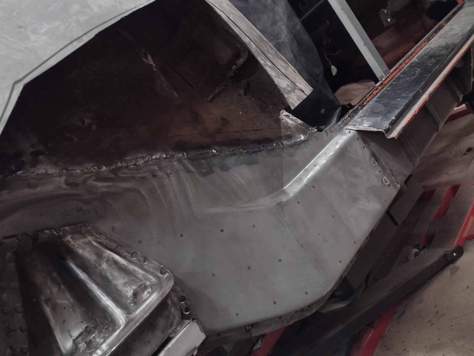
Then some repair on the inner firewall:
And the pan:
And its reinforcement:
And the triangle, no chance to repair the old one so I made a new one:

And that is one side done:
Stay tuned
Antoine
After a bit of Paint/gravel protection removal, it wasn't looking promising:
And not much better without the jack point triangle :
So I prepared the floor pan:
And made some cut:
Now I could see the damages better:
So I made a template :
And the part, from cutting to adjusting to welded:
Then some repair on the inner firewall:
And the pan:
And its reinforcement:
And the triangle, no chance to repair the old one so I made a new one:
And that is one side done:
Stay tuned
Antoine
Making your own replacement panels = cool! Nice work.
Thoroughly impressed, and thinking that had I sent you a care package of Restoration Design parts, you'd be done already  .
.
That is real dedication to make what is commercially available.
That car will be a part of you when you're done.
. That is real dedication to make what is commercially available.
That car will be a part of you when you're done.
 That was cool man, making your own doughnut/jack point! Amazing! Way to go Antoine.
You are making me crave some rust work
Great work.
Great work.
Forming your own panels... And the feeling you get when you say "I made that!" 
Nice work.
And the feeling you get when you say "I made that!" Nice work.
jack donut is a work of art.
you are good mate, very good.
i can see that phoenix red peeping through everywhere - just wants to get out into the light of day.
you are good mate, very good.
i can see that phoenix red peeping through everywhere - just wants to get out into the light of day.
Thanks a lot guys, the support here means a lot to me!!
You're all right, I could have win a lot of time buying parts..but the fun for me is in the building
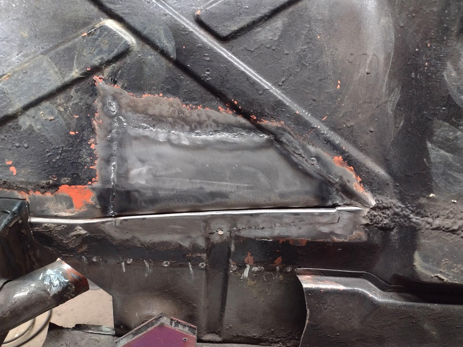
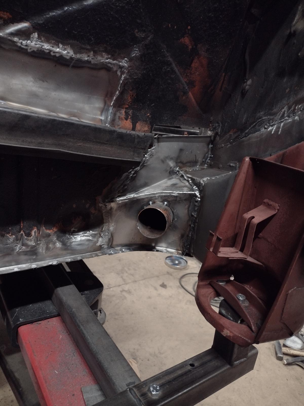
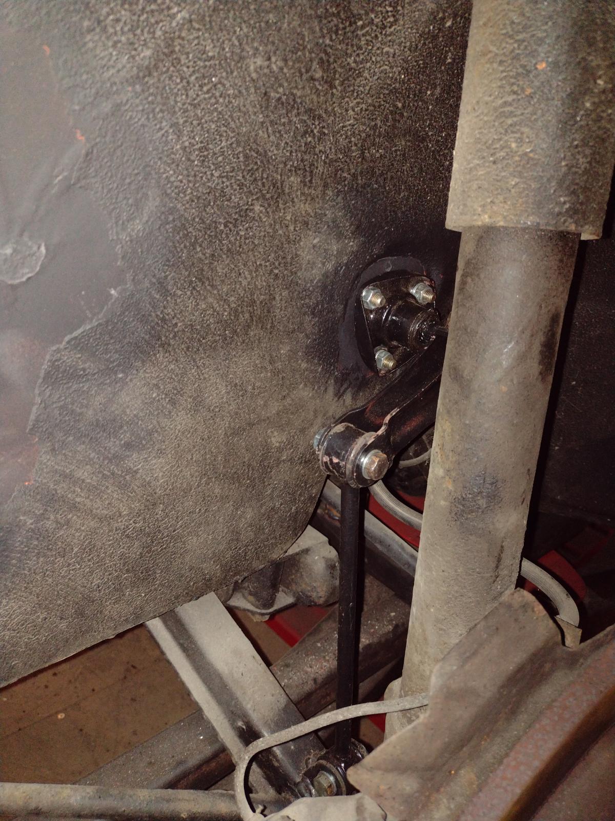
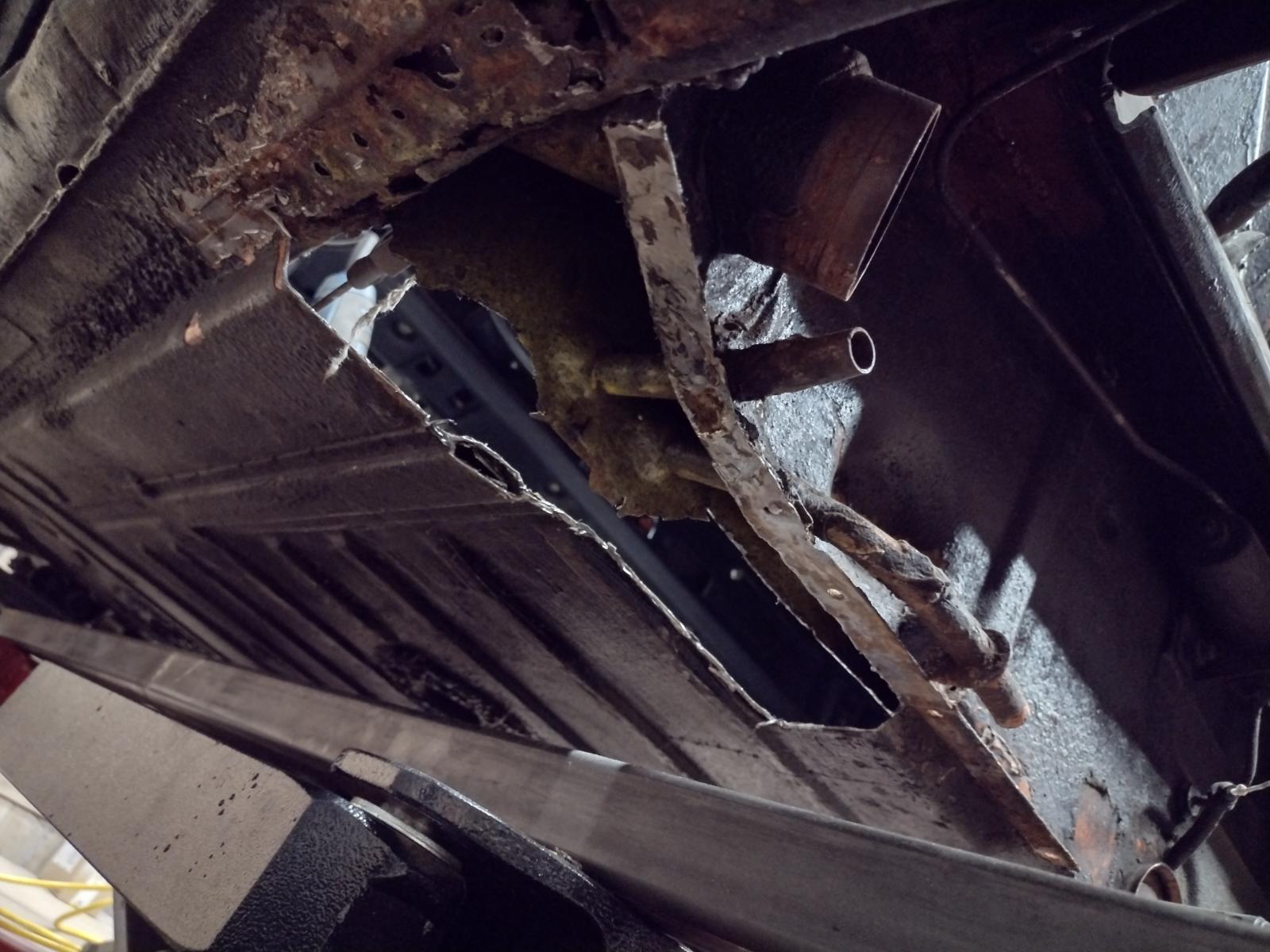
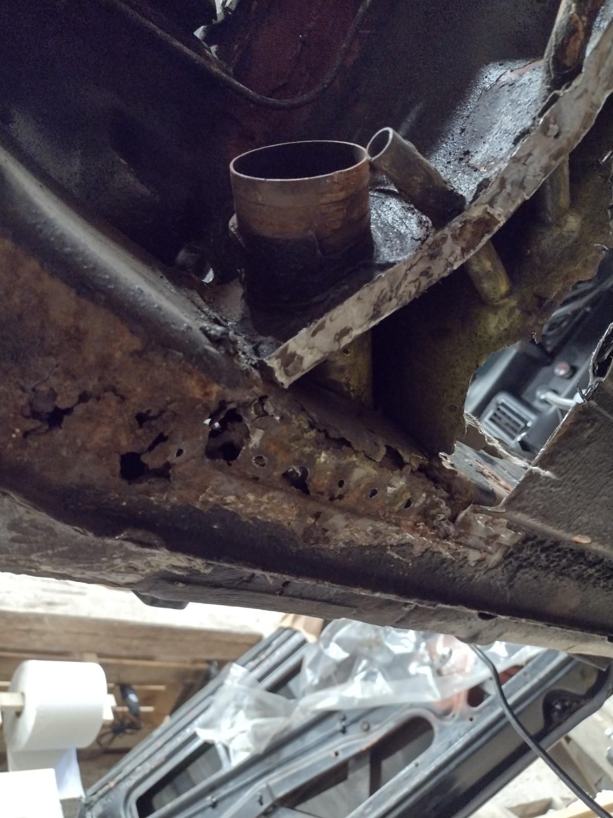
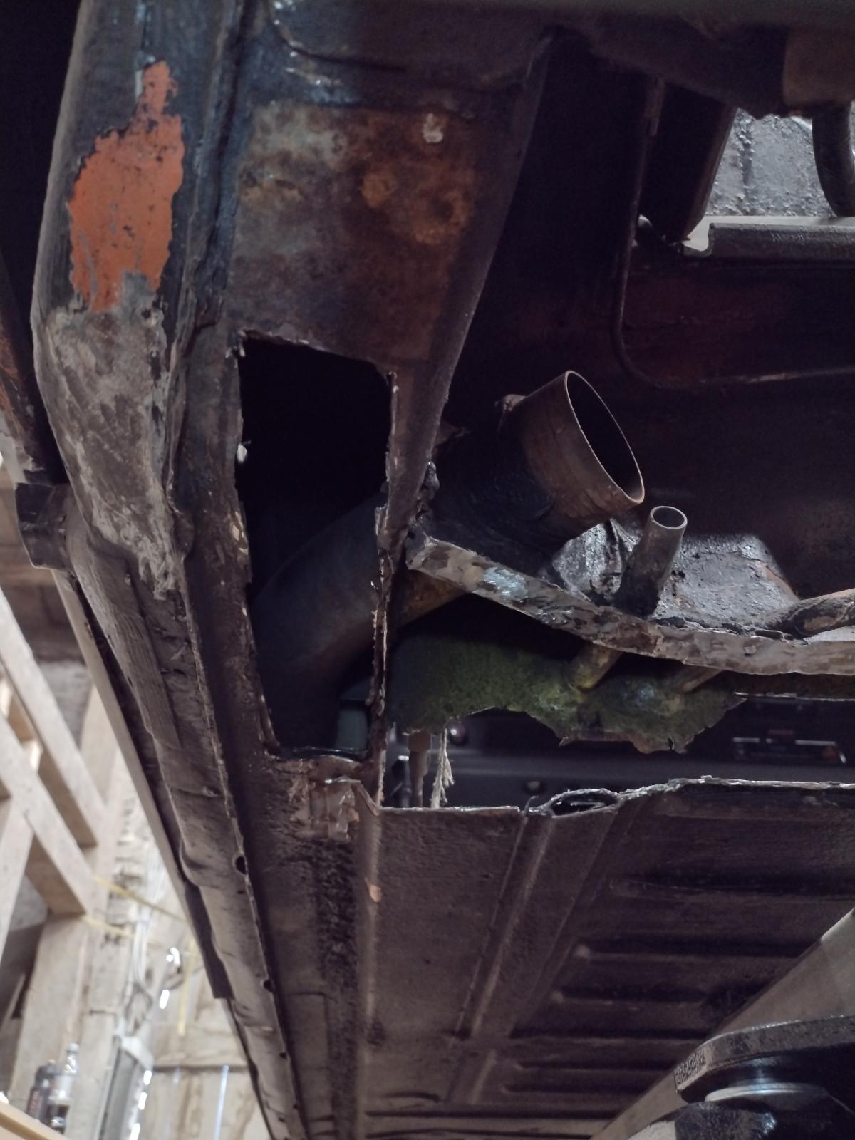
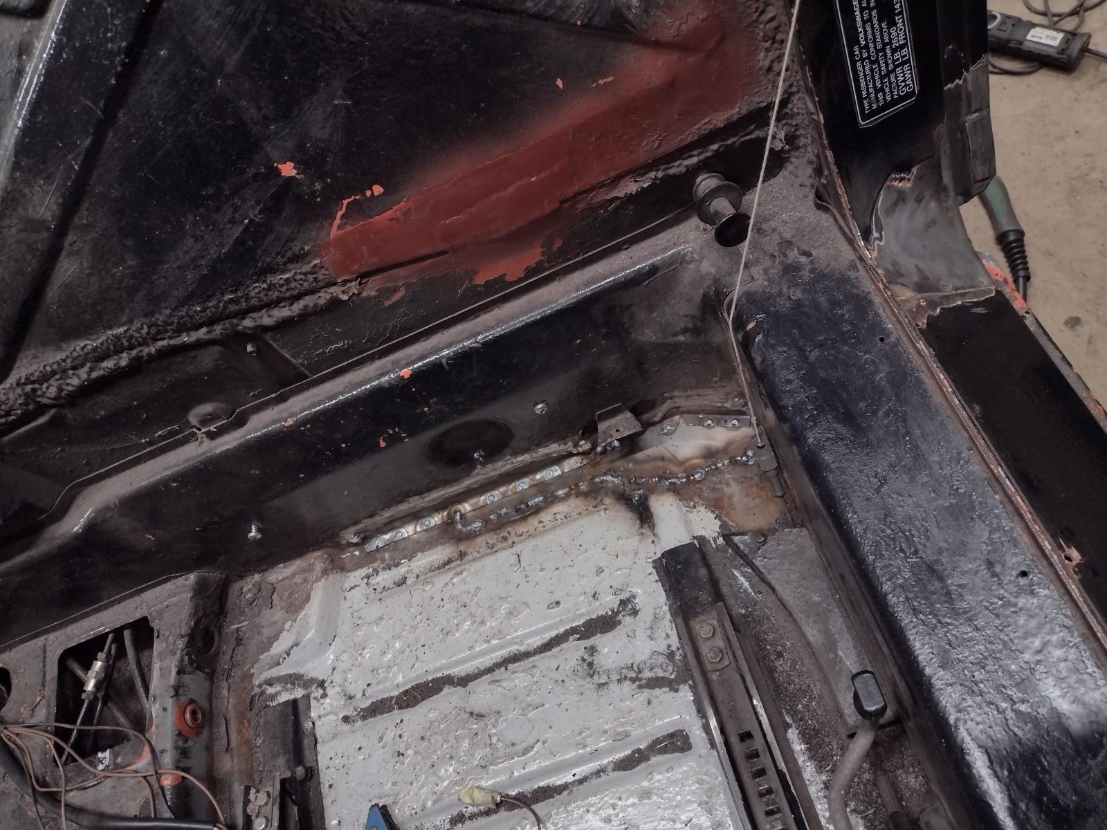
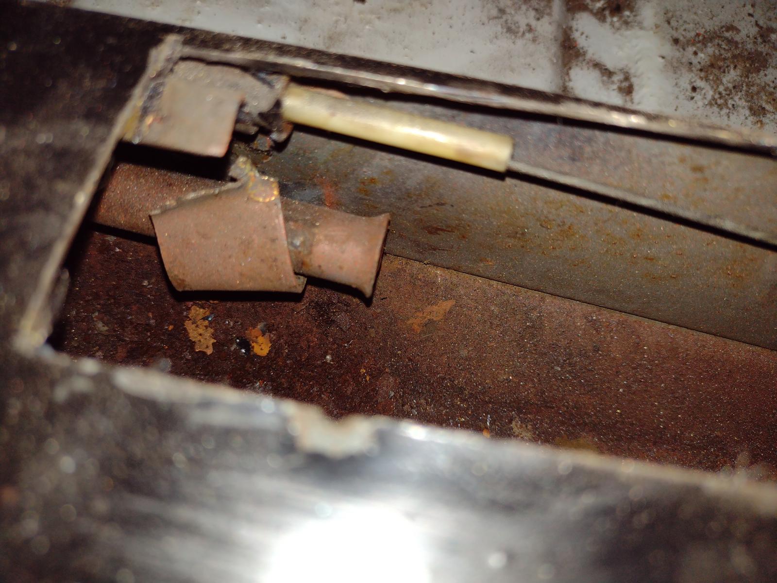
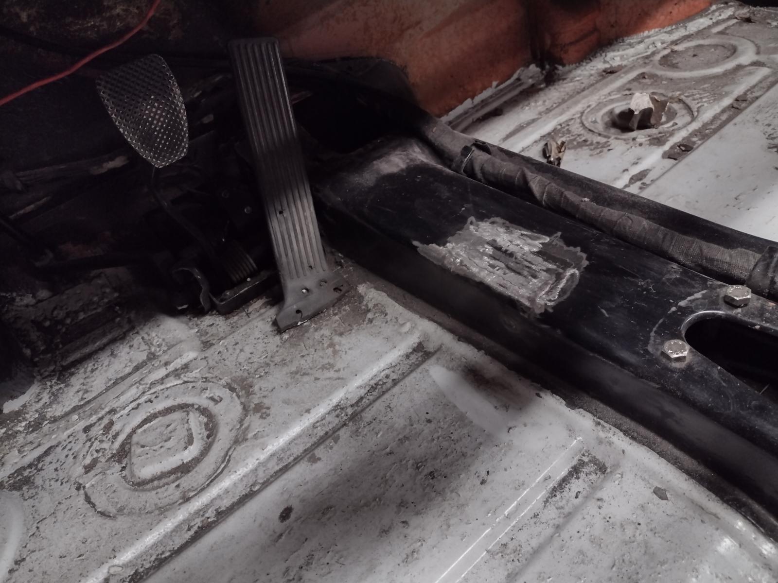
So, next I fixed the clutch tube.
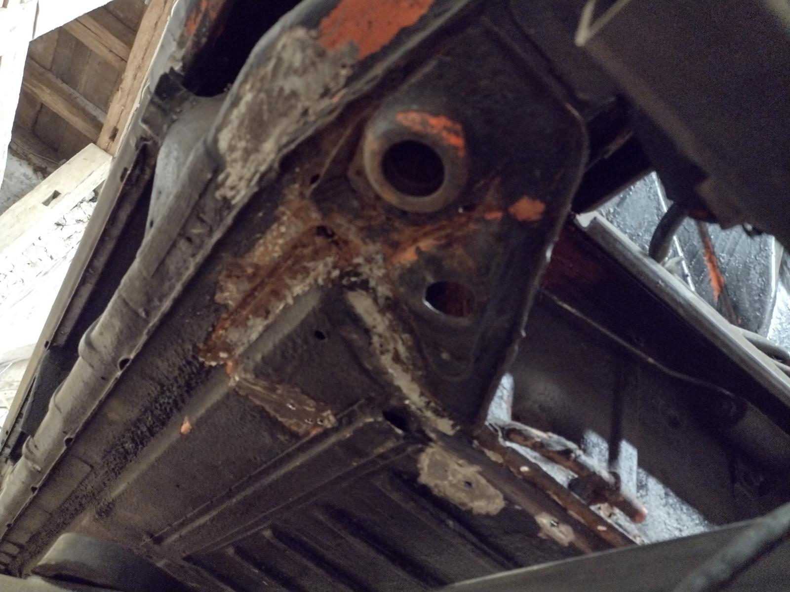
First the part on the firewall, I don't know what a PO was thinking with this thick piece?!
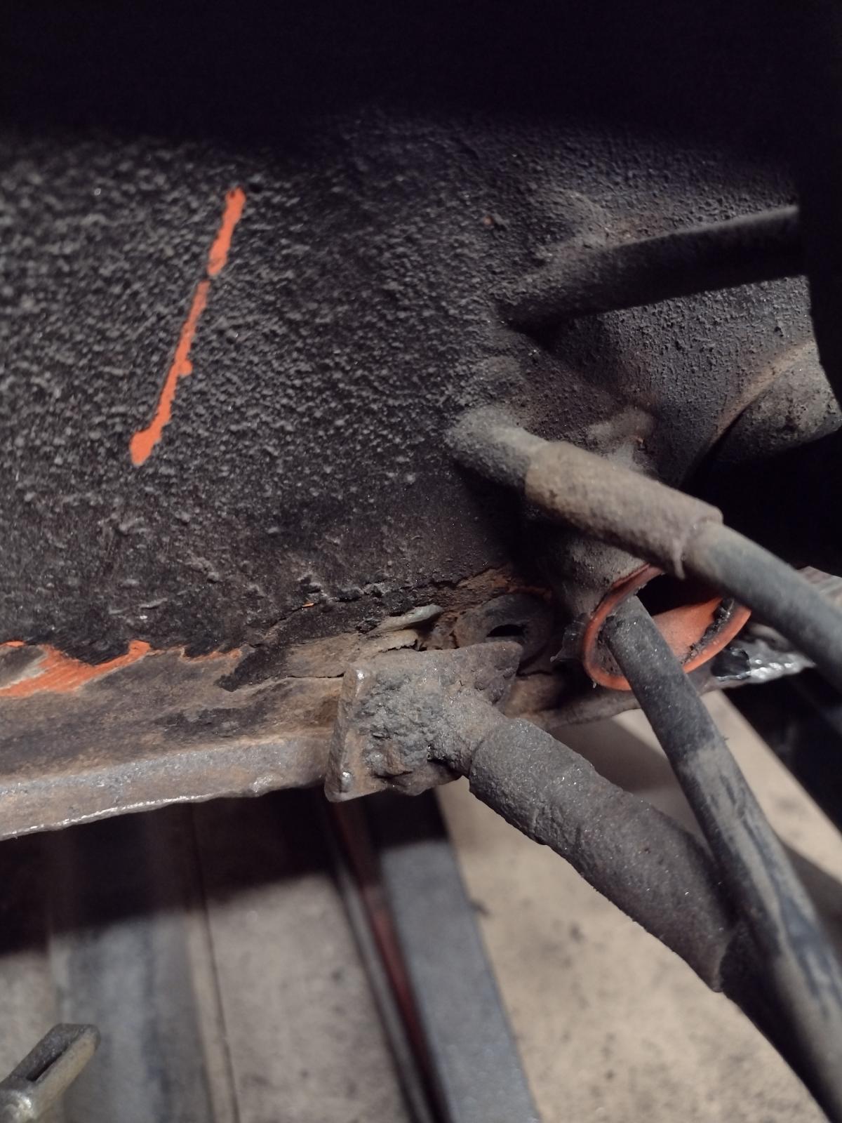
So I removed it and found a damaged firewall:
So removing what is damaged:
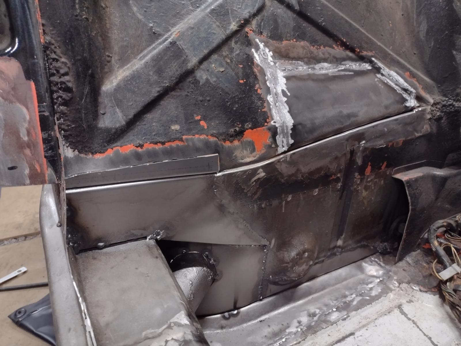
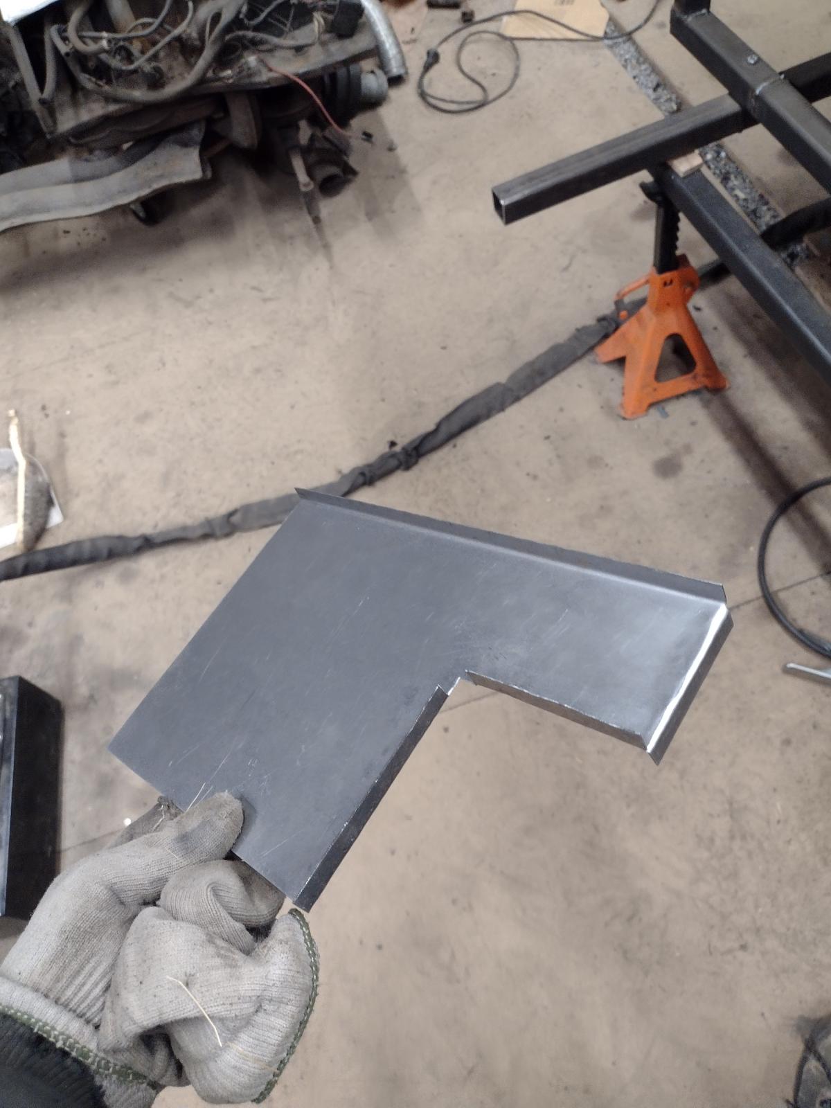
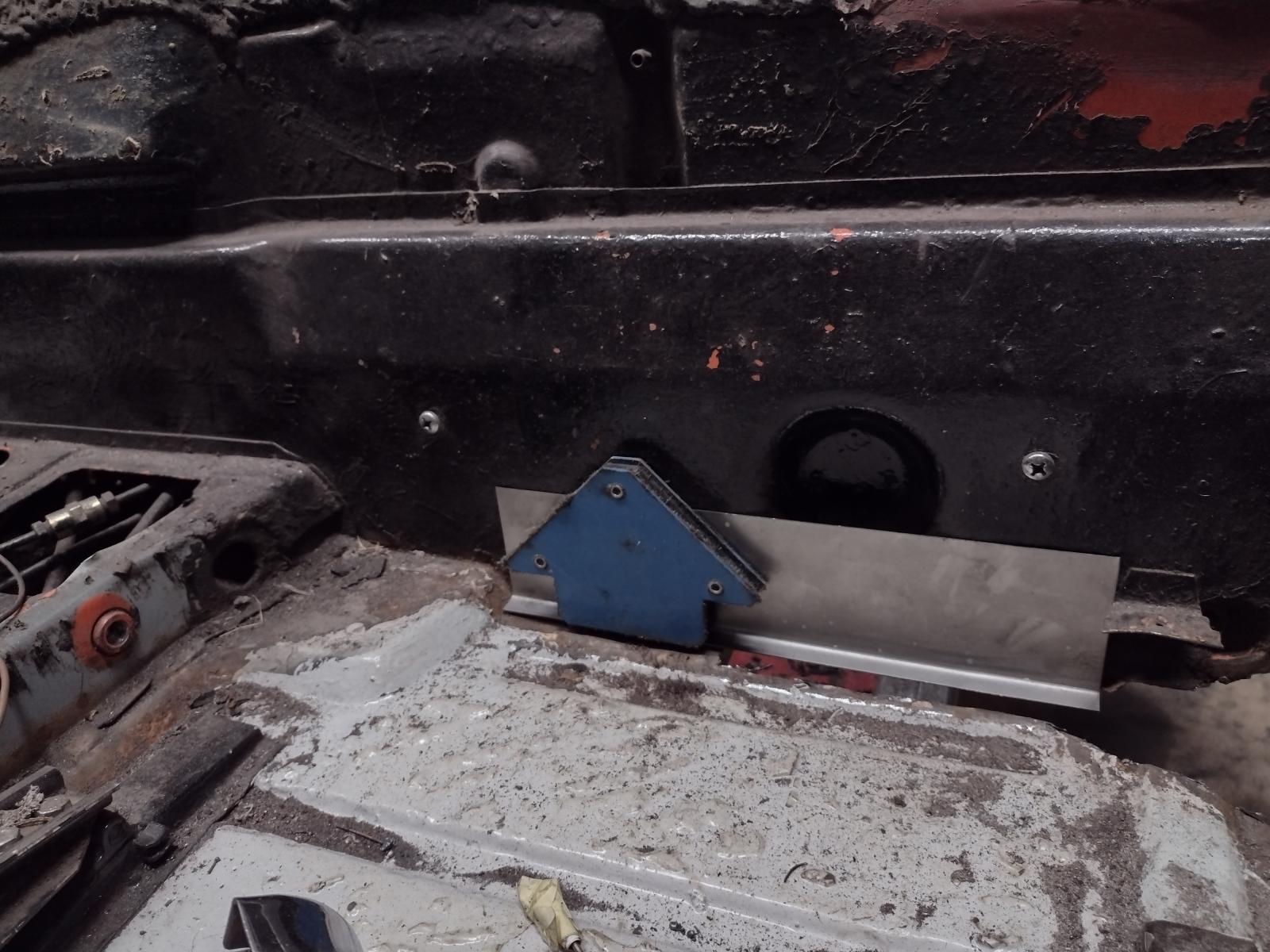
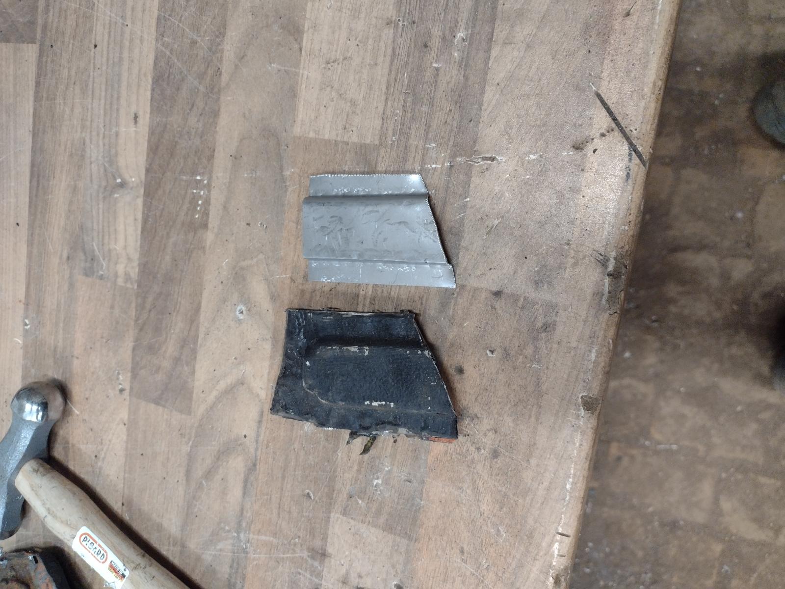
Making the patch:
Adjusting:
Welded:
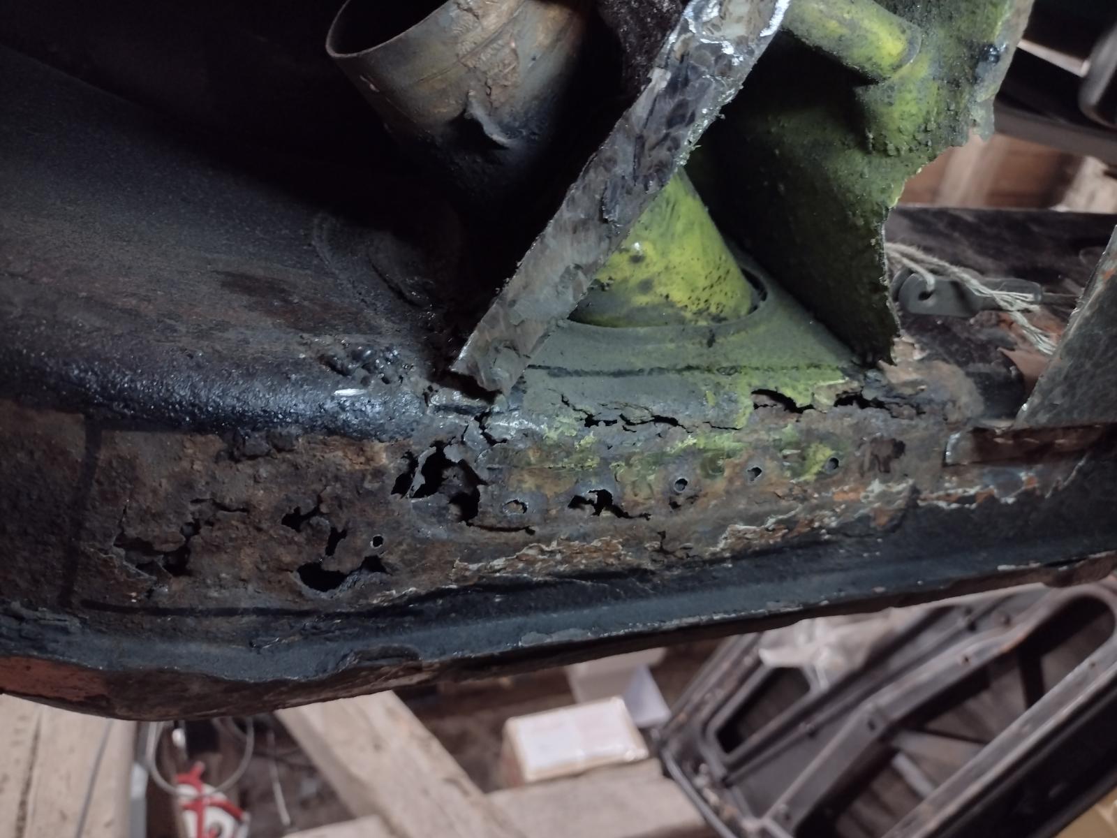
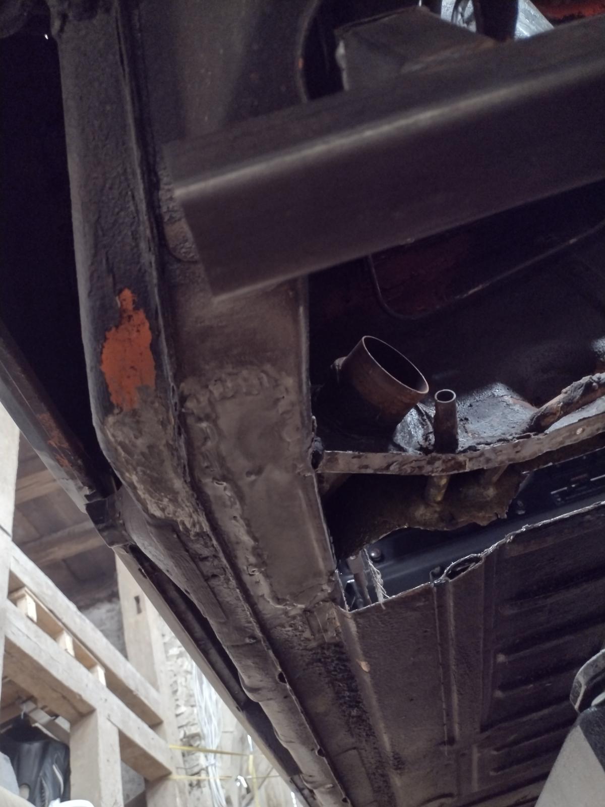
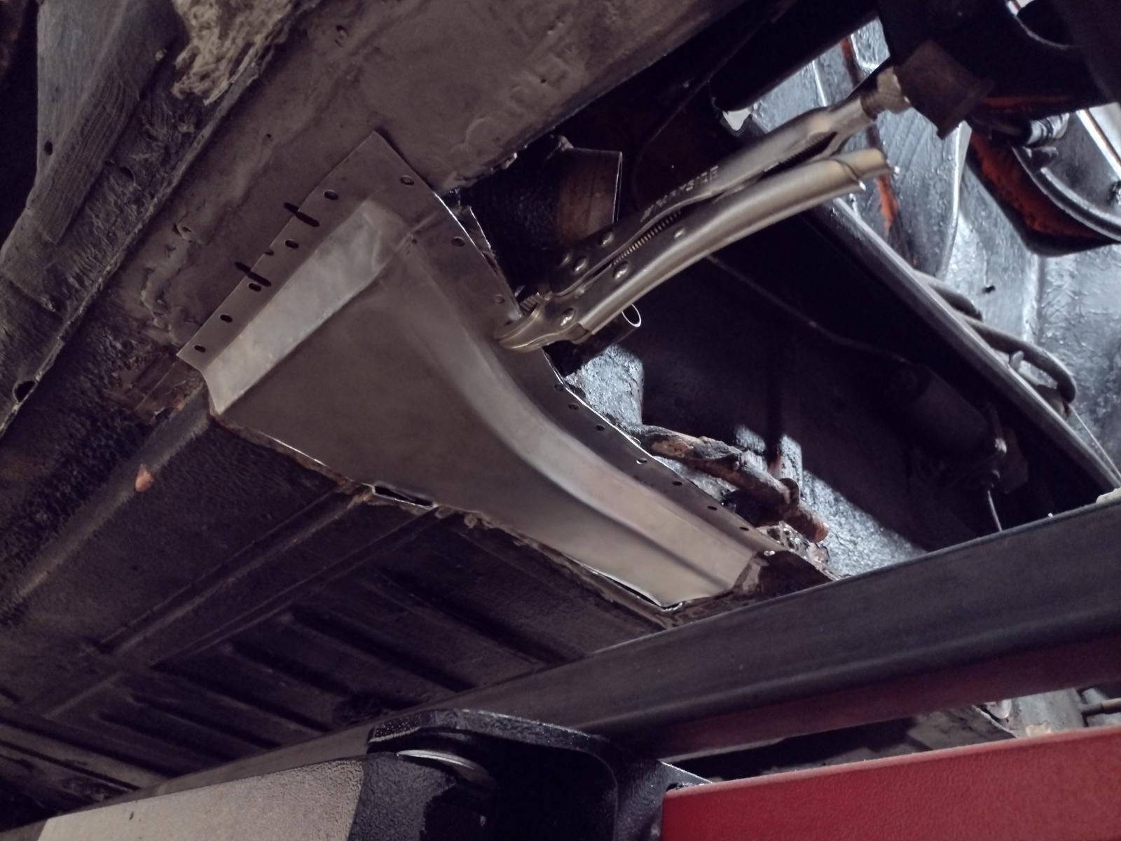
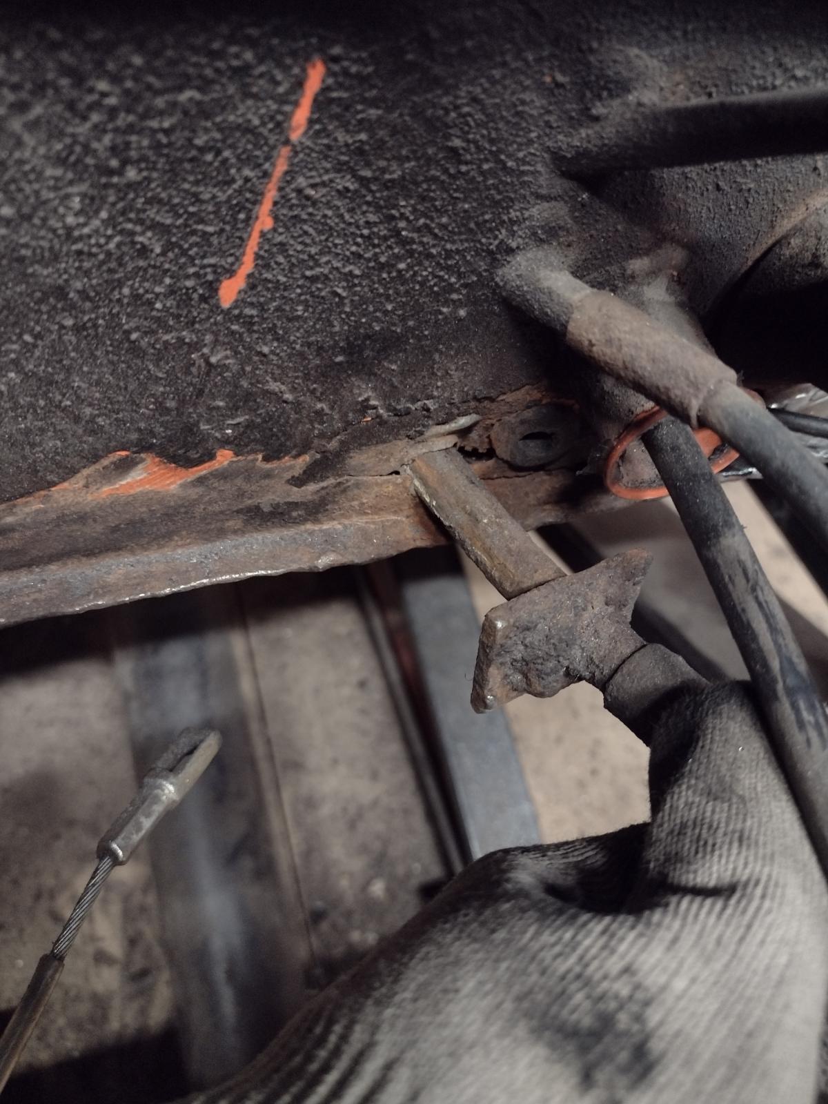
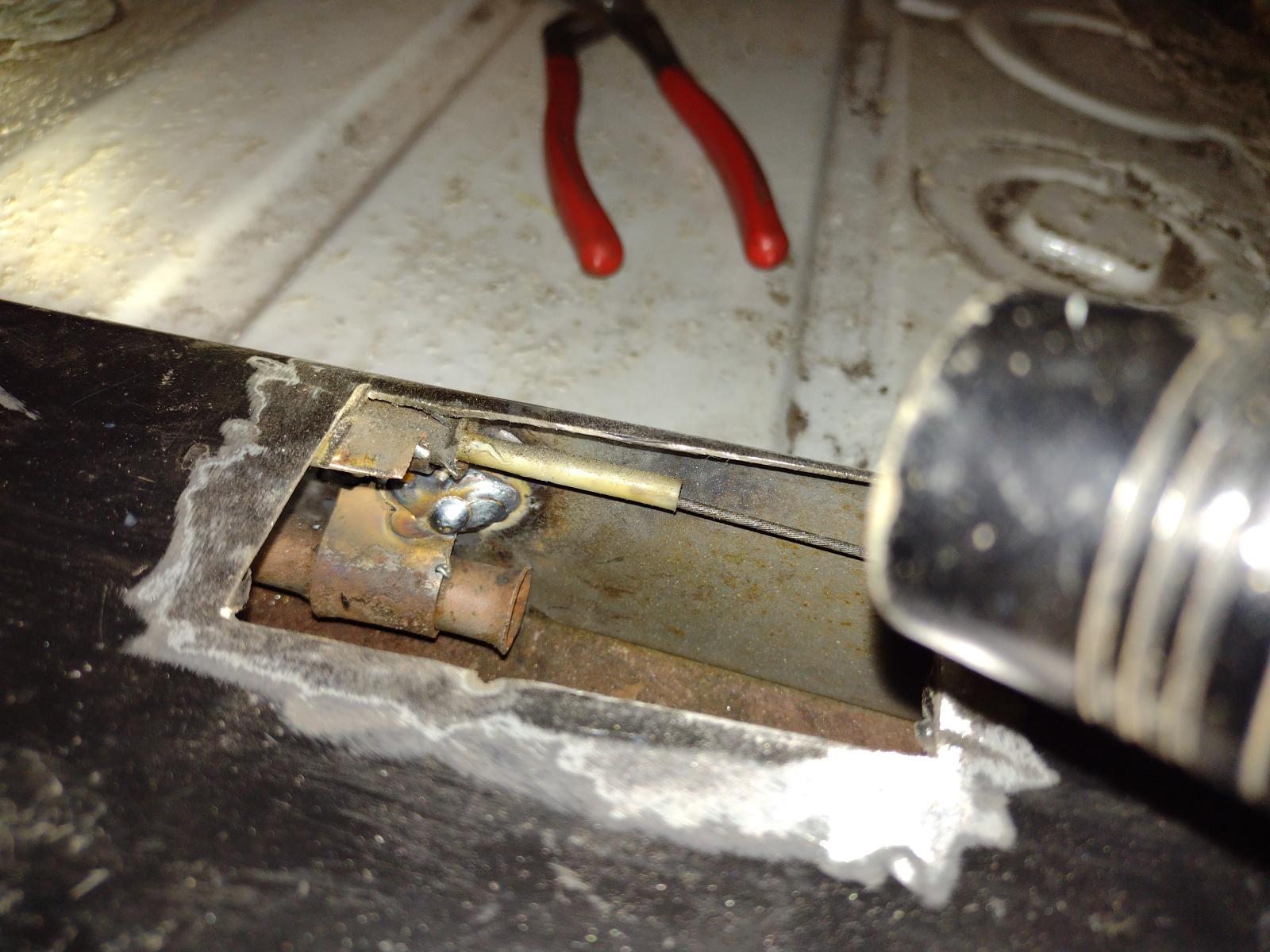
And the front fixation, cut the access :
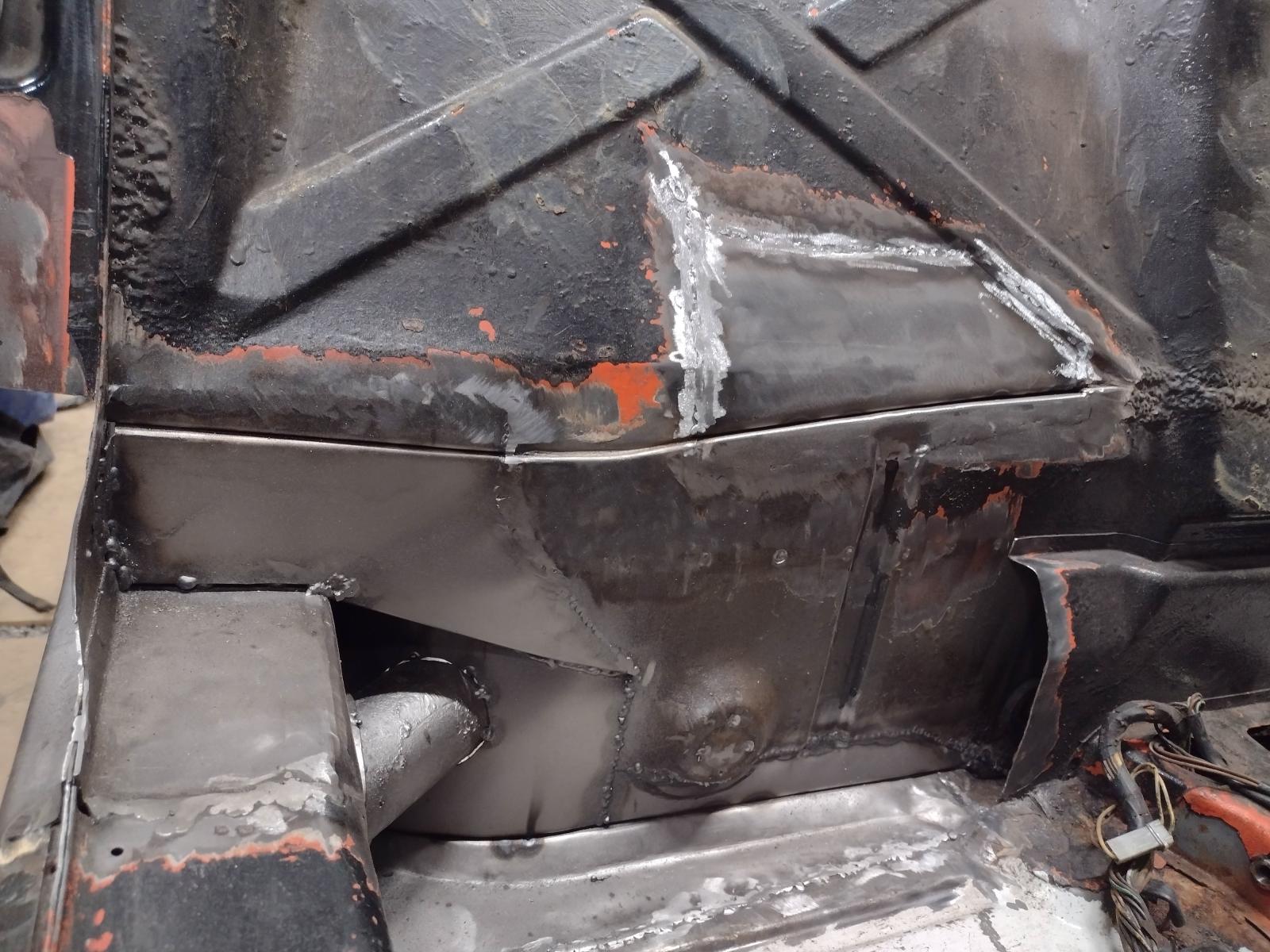
The issue:
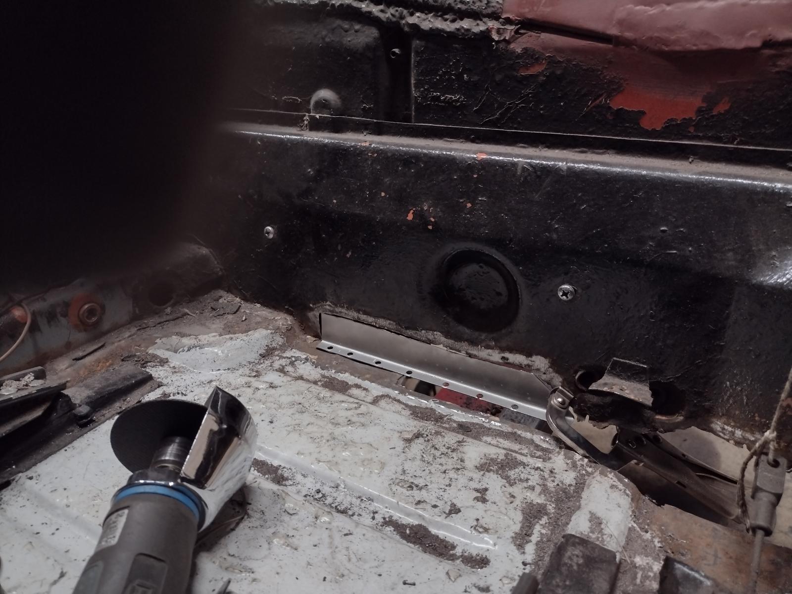
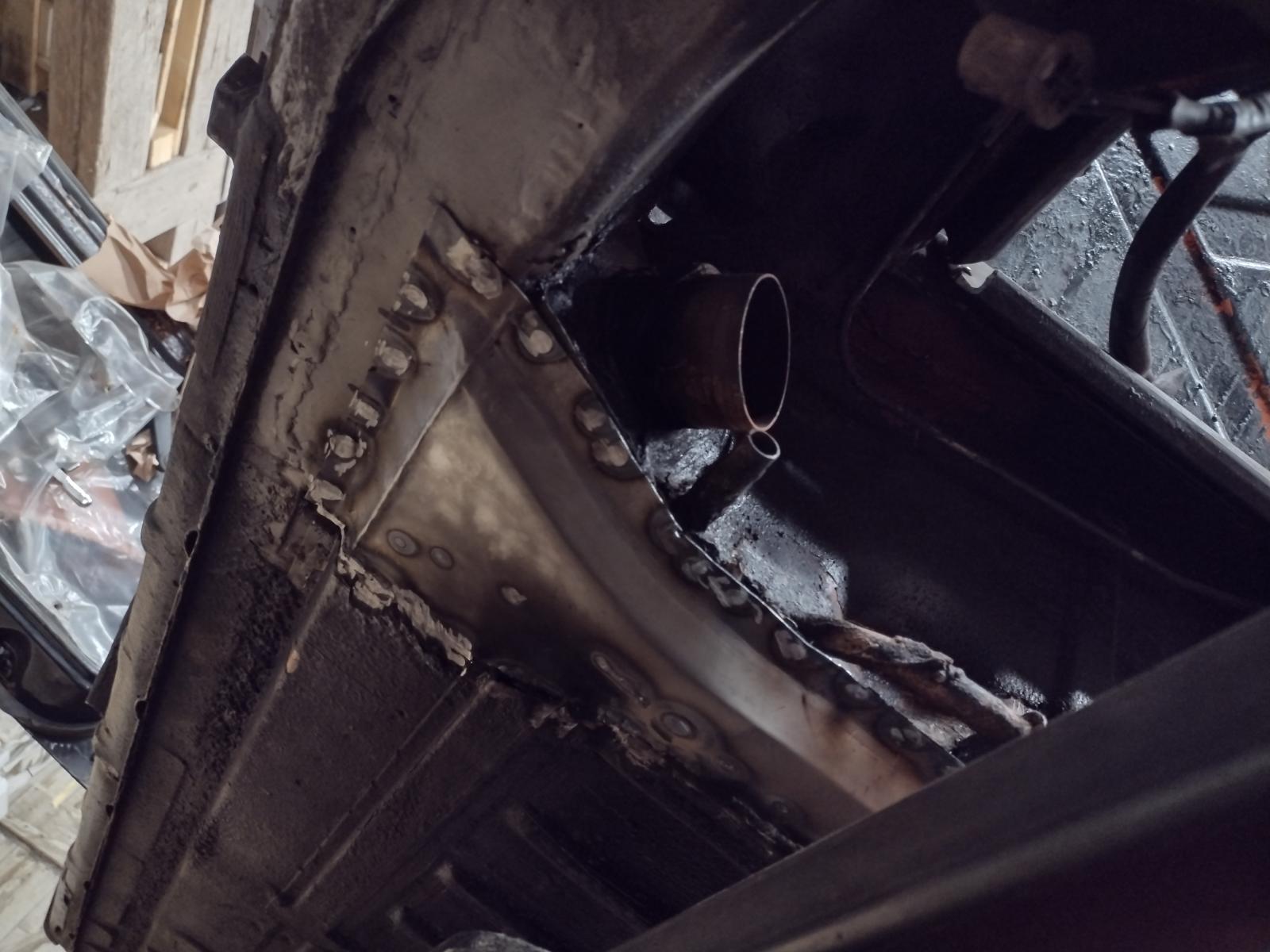
Welded (pic was ongoing, I welded the whole length but forgot to take a picture):
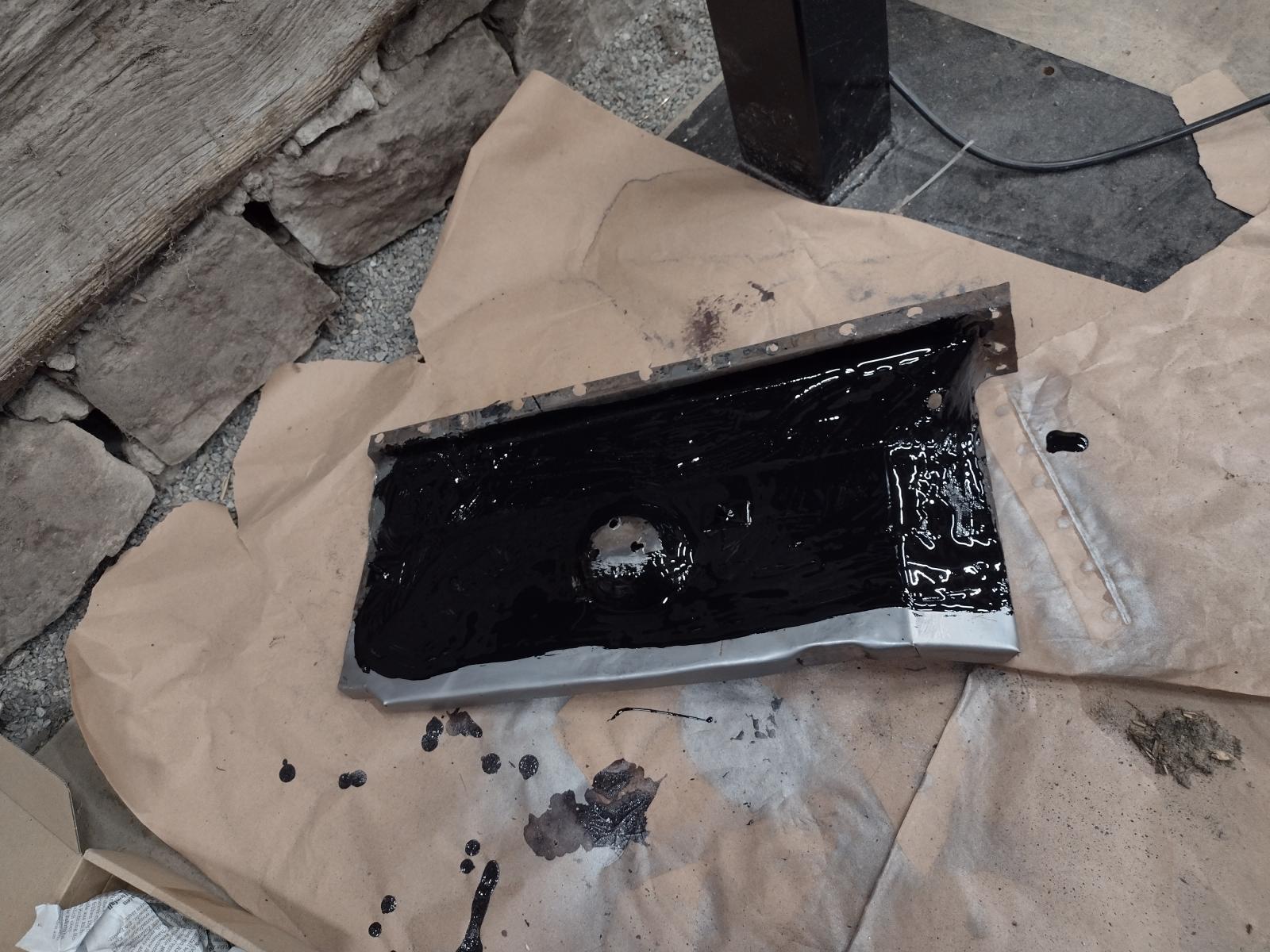
And closed:
Stay tuned
Antoine
You're all right, I could have win a lot of time buying parts..but the fun for me is in the building
So, next I fixed the clutch tube.
First the part on the firewall, I don't know what a PO was thinking with this thick piece?!
So I removed it and found a damaged firewall:
So removing what is damaged:
Making the patch:
Adjusting:
Welded:
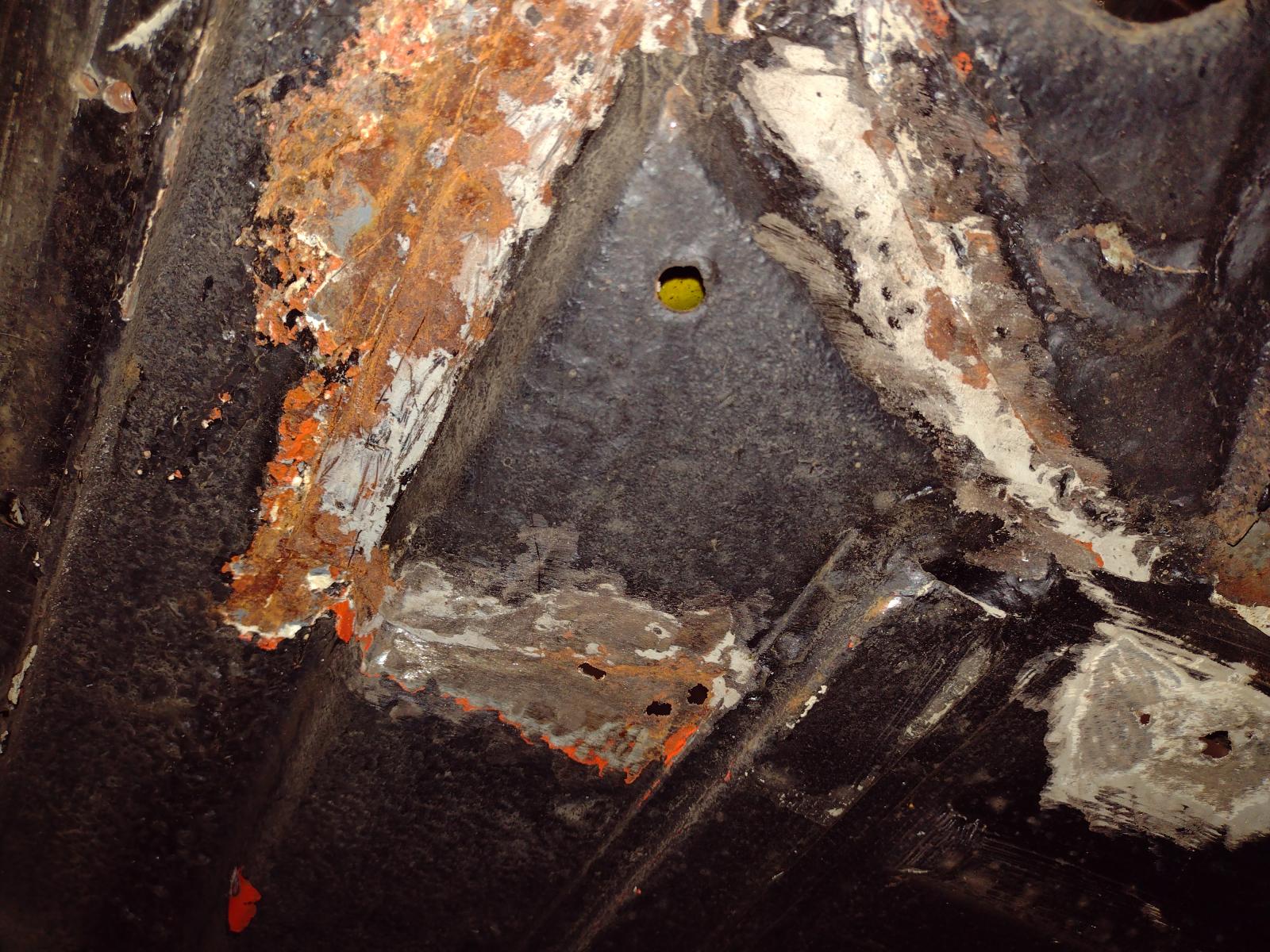
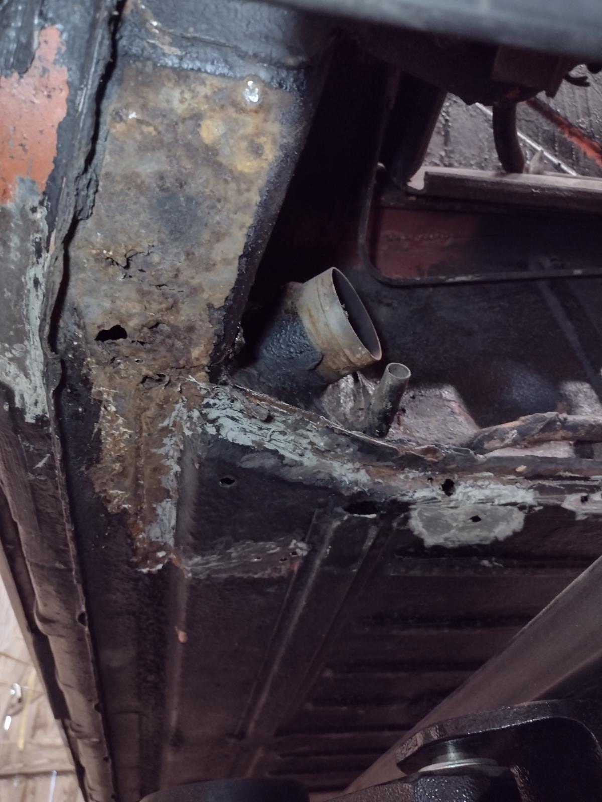
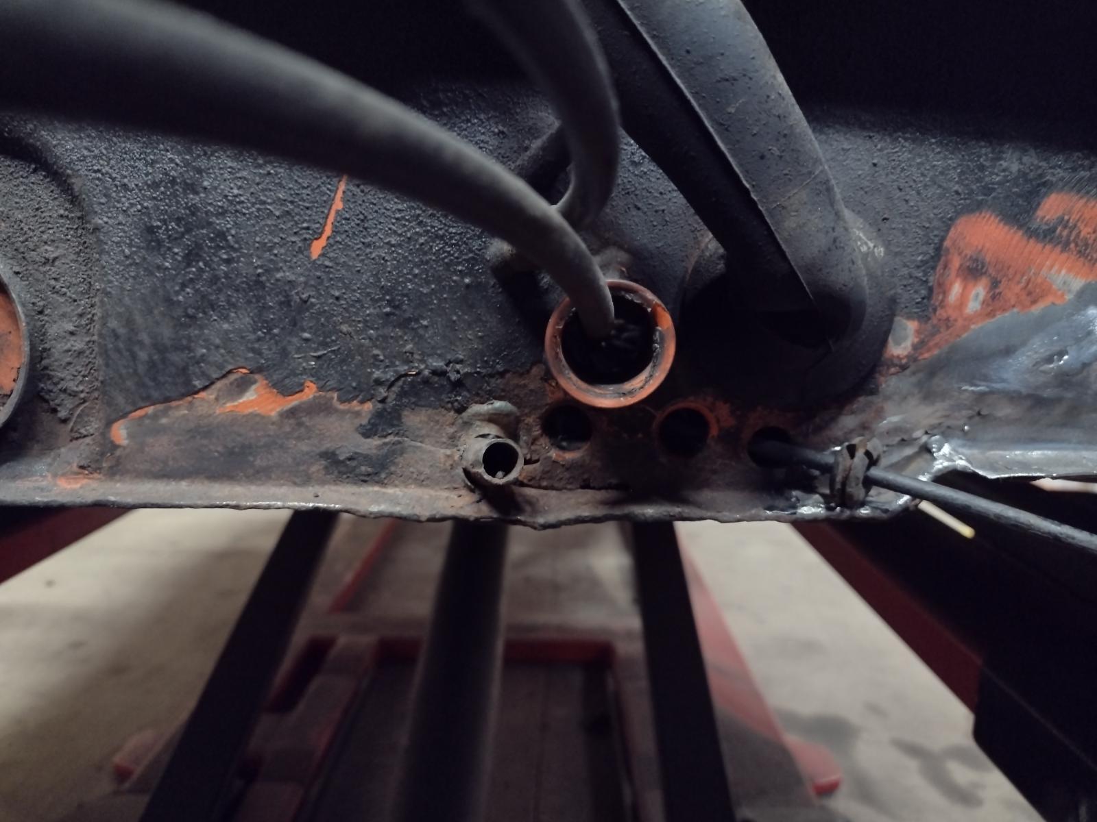
And the front fixation, cut the access :
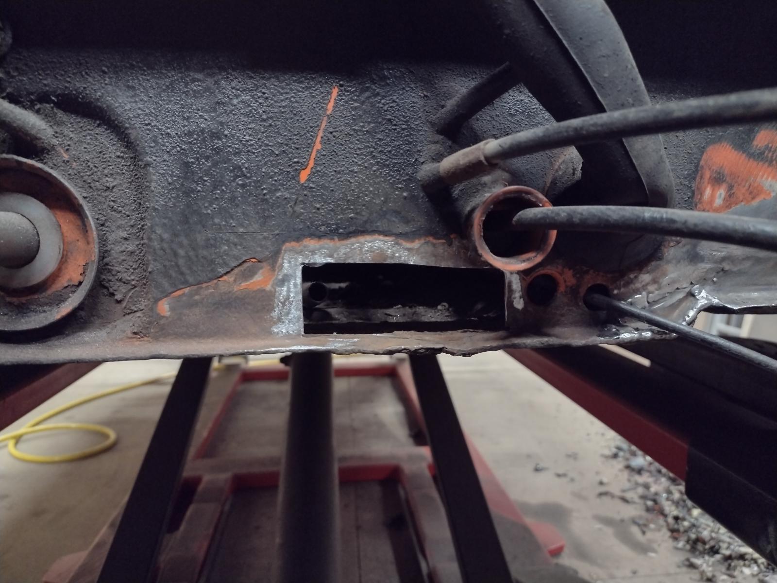
The issue:
Welded (pic was ongoing, I welded the whole length but forgot to take a picture):
And closed:
Stay tuned
Antoine
At this phase in their life the clutch tube failures are pretty common.
This is so common with 914's. Prior owners attempt to fix but they only look at the symptom (the cracked bulkhead) and then slap a "fix" onto it. Meanwhile they never address the root cause (the broken clutch tube restraint) that is leading to all the flexing in the 1st place.
Nice job fixing the clutch tube at both ends! It will be good to go for decades!
This is a "lo-fi" version of our main content. To view the full version with more information, formatting and images, please click here.