Got the hose for the PSP yesterday. I'm only keeping it for the pulley. I'll run a loop with fluid. And the ignition switches I needed cam in - so I hope to get this finished up and ready to test this weekend.
I'll post an invite to see if anyone's interested in coming out to SE AZ for some 914/SHO fun & see if this thing runs.
ENjoy your Thanksgiving!
Full Version: 3D914s 914-6 SHO 3.2L v6
Purdy 74.
Can't wait til that SHO gets running. I remember burying that speedo coming back from Flint to Lansing one night.
Can't wait til that SHO gets running. I remember burying that speedo coming back from Flint to Lansing one night.
Wiring is all in and going through double-checks now. Expect to do the turn-over to build oil pressure this weekend, then next weekend is the bench-test day to get this SHO started.
Click to view attachment
Click to view attachment
Click to view attachment
Click to view attachment
HooRa! Got oil pressure. Just finished spinning up the SHO motor to test oil pressure before starting it the first time (next Saturday).
Using the stock instrument cluster simplified things. With power on I got Oil, Batt, and Check Eng lights. Once I started the motor, all went out except oil pressure. About 45 seconds later - oil pressure went out. Gotta love it when things work.
Here's the video.
Using the stock instrument cluster simplified things. With power on I got Oil, Batt, and Check Eng lights. Once I started the motor, all went out except oil pressure. About 45 seconds later - oil pressure went out. Gotta love it when things work.
Here's the video.
Hi Gerard,
I'd like to make a run down to Benson one of these weekends and check out your project. It's looking really good.
Guy
I'd like to make a run down to Benson one of these weekends and check out your project. It's looking really good.
Guy
Well we had a nice gathering for the "Get the SHO Started - Take 1". Here's some of the cool vehicles that showed up.
Jason's 993 Carrera
Click to view attachment
Rich's SHO
Click to view attachment
Guy's 914-V8
Click to view attachment
Jason's 993 Carrera
Click to view attachment
Rich's SHO
Click to view attachment
Guy's 914-V8
Click to view attachment
OK, now for the event details. Let's just say we had partial success. The motor started, fuel pump & relays all worked, tach signal was good, etc.
Here's the video.
There was some bad news though. Something in the wiring caused the PCM to go into limp-home mode - permanently. We weren't able to even pull codes on it. We tried a second PCM and got the same thing.
So now it looks like I'll be retracing all the wiring (again) to find the issue. Keep ya posted.
 You'll get it figured out.
I'm afraid of the same thing when I start mine. I did have my ECU flashed to take out all the devices that can put it into limp mode. We shall see...
Keep at it. I want to see that thing drive!

QUOTE(kg6dxn @ Dec 8 2012, 10:03 PM) 
You'll get it figured out.I'm afraid of the same thing when I start mine. I did have my ECU flashed to take out all the devices that can put it into limp mode. We shall see...
Keep at it. I want to see that thing drive!
Thanks, Mike
Hi Gerard,
Glad I came down to see your project yesterday, as well as see you again since its been a few years. I know you'll do fine chasing down a few snags. That's the fun of doing these conversions (except when it costs $$). You're not that far away from me. We'll have to keep in touch. Thanks again for the food too.
Guy
Guy, Glad you could make it & I can use the support. As much as I'm enjoying this approach, I sometimes wish I'd taken a simpler route. Those V8's like yours sure sound sweet!
When you get that Yamaha engine dialed in you will be smiling from ear to ear. My brother had a '91 SHO and that car screamed. In a 2100 pound 914 that is going to be blistering fast.
Yamaha engine? Enlighten me please?
QUOTE(Tilly74 @ Dec 13 2012, 02:00 PM)
Yamaha engine? Enlighten me please?
Yes, built for ford by yamaha.
http://en.wikipedia.org/wiki/Ford_SHO_V6_engine
Gerard, how is the wire tracing going?
QUOTE(Tilly74 @ Dec 13 2012, 05:00 PM)
Yamaha engine? Enlighten me please?
Tilly, here's a pic of the 3.2L SHO motor on the test stand.
Click to view attachment
QUOTE(AZ914 @ Dec 14 2012, 01:32 PM)
Gerard, how is the wire tracing going?
Jason, not too bad. Here's the codes that we pulled, so I've started chasing down the wiring first, then follow with component check-out.
- 26 - MAF (out of range)
- 51 - ECT (coolant temp signal too high)
- 95 - FP ground circuit (Fuel pump: open, bad ground or always on; bad fp ground or open between fp and pin 8 at PCM)
- 65 - Check intermittent HO2S (signal or ground)
So far I've verified the wiring is good for the heated O2 sensors. It's just that I have 4-wire O2 sensors (for 3.2 ECU) when I should have 3-wire since I'm using the 3.0L ECU. Using the manual trans ecu (PCM) from the 3.0L setup is easier as far as the computer goes - but the differences in wiring have tripped me up more than once.
Wiring checks for all others (MAF, FP, & ECT) look good also. There is one thing that's odd though. I'm not using the stock Constant Control Relay Module (CCRM), so I came up with my own custom one. Since I don't have a schematic for the 3.0L PCM's CCRM, I've had to improvise with the 3.2L CCRM diagram. There's one case where a diode is used to prevent a ground circuit from flowing back into the relay coil inputs for several of the relays. Since I haven't added that particular relay into the circuit yet I didn't bother with the diode, but I suspect it may be needed anyway. I think it's more than coincidence that the failing sensors tie through the same grounding circuit where that diode was used. We'll see.
I'm not completely done yet, but all my checks on the wiring so far are coming out fine. I'll be testing the sensors themselves this weekend & I do have to replace the 4-wire O2 sensors for 3-wire, so when they come in it'll be time for another test run.
I also have a D-type ICRM (CCRM) coming that I will try out if I continue to get errors. This is the stock relay module for FP, ECU, Fans, & A/C. Also gonna try a direct reset of the JX2 PCM that appears to be frozen. Keep your fingers crossed.
I also have a D-type ICRM (CCRM) coming that I will try out if I continue to get errors. This is the stock relay module for FP, ECU, Fans, & A/C. Also gonna try a direct reset of the JX2 PCM that appears to be frozen. Keep your fingers crossed.
See if you can find an ECU breakout box. When I did my 914 5.0L Ford conversion, I had trouble running. I plugged in the breakout box, ran some tests and found a bad ignitor and low fuel pressure.
You might be able to find an old used no more breakout box somewhere
May not be the exact one...
http://www.ebay.com/itm/Ford-Rotunda-104-P...884&vxp=mtr
You might be able to find an old used no more breakout box somewhere
May not be the exact one...
http://www.ebay.com/itm/Ford-Rotunda-104-P...884&vxp=mtr
QUOTE(kg6dxn @ Dec 20 2012, 01:01 PM)
See if you can find an ECU breakout box. When I did my 914 5.0L Ford conversion, I had trouble running. I plugged in the breakout box, ran some tests and found a bad ignitor and low fuel pressure.
You might be able to find an old used no more breakout box somewhere
May not be the exact one...
http://www.ebay.com/itm/Ford-Rotunda-104-P...884&vxp=mtr
Mike, I'll look into it. IIRC these are EEC-III or IV. Thanks for the tip.
Some good news today. I installed the 3-wire O2 sensors and worked on the MAF sensor today. The MAF was cleaned and passed the various tests, so I'm concluding its OK.
There were some good signs that the JX2 PCM is fine. The startup sequence was correct.
I was able to check codes and the sequence looked correct.
Now on to other issues.
There were some good signs that the JX2 PCM is fine. The startup sequence was correct.
- Key on - CEL light & Low Fan comes on
- Key on - FP spins up
- Key start - CEL light, low fan & Batt goes out
- Run - Oil light goes out
- Run - CEL come back on after a short time
I was able to check codes and the sequence looked correct.
- Key on - CEL light & goes off
- On - Relay cycles on & off
- On - Low Fan cycles on & off
- On - Two single CEL blinks
- On - starts cycle of CEL Codes
- On - one final CEL blink
Now on to other issues.


Slow progress. Been chasing wiring issues for most of the last two weeks. Got some of the running/code issues addressed, still chasing the other two:
Located and ordered a FP Regulator. Took off the intake to remove the bad one. Took all of five minutes to get the intake off - this is why I decided to do all the testing on a stand. Soooo much easier.
Looks kinda cool even without the intake.
Click to view attachment
- 51 - ECT (signal too high) - Bad sensor, new one on order
- 65 - Check intermittent HO2S (signal or ground) - Wrong sensors, replaced 4-wire with 3-wire to match J2X PCM.
Located and ordered a FP Regulator. Took off the intake to remove the bad one. Took all of five minutes to get the intake off - this is why I decided to do all the testing on a stand. Soooo much easier.
Looks kinda cool even without the intake.
Click to view attachment
Well, got around to doing test run #2. Unfortunately the results were the same. Even with the new FP regulator it still seemed to be flooding. Beginning to think the entire fuel system needs to be pressurized. I'm doing my test with an open can with fuel supply and return hoses into it.
Also got the same PCM codes as last time. I did get another code (81) earlier, but it has cleared since. Looks like I'll be wiring up a stock "D" ICRM/CCRM and trying that. Keep ya posted.
Also got the same PCM codes as last time. I did get another code (81) earlier, but it has cleared since. Looks like I'll be wiring up a stock "D" ICRM/CCRM and trying that. Keep ya posted.
Spent last week getting the stock "D" type ICRM/CCRM (relay module) hooked up in place of my custom one. Reviewed all my ignition wiring. Ready for test run #3.
OK, got around to test run this morning. I still don't have a throttle cable hooked up, so I set the idle at 2000rpm so the motor can warm up.
Here's the video.
Also did another video with the idle set down to 1000 rpm.
Looks like I got me a running SHO motor.
OK, got around to test run this morning. I still don't have a throttle cable hooked up, so I set the idle at 2000rpm so the motor can warm up.
Here's the video.
Also did another video with the idle set down to 1000 rpm.
Looks like I got me a running SHO motor.
Sounds pretty good! Now stuff it in that car already!!!!

if you need some help putting that baby in, let me know!
Thanks, but it will still be a while. Now that the motors running, I need to get all the wiring I have in place fully documented. In the meantime I'll get back to finishing up the engine bay so I can do a test fit. Will definitely need some help then.
Found a stripped thread for one of the valve cover bolts. These heads are aluminum, so a time-sert will be needed. Since it wasn't 45 degrees today, I was actually able to get some work done in the garage. Shims came in so I finished up the valve adjustment. Some of the measurements I took previously were slightly different (+ .001 or .002). I was able to adjust my shim usage to get my desired gaps.
For anyone unfamiliar with the time-sert install process here are some pics. I went with a kit so I wouldn't have to chase around looking for the right drill bit, tap, etc. The kit is sized by the thread you're repairing - so for the cover bolts it was a M6-1.0x10mm. All the work can be done by hand - power tools would be complete overkill. First & easy step was to drill out the hole, then use the c-bore tool. These tools are nice quality, so even work by-hand goes quick.
They suggest using compressed air to blow out material, but with the cover off I didn't think that was so wise, so I used my small vacuum instead.
Click to view attachment
Result was a nice clean counter-bore.
Click to view attachment
Next was the tap. Like the drilling, I used a 90deg allen wrench as an angle guide since there isn't much room. Oil was also needed to cut cleanly. Note for reference: the fitting for the tool on the tap was larger than the others so a #12 or larger T-handle is needed.
Click to view attachment
Finished result. Already got the cover back on, but will wait till morning to torque it down.
Click to view attachment
Hoo-Ra! Motor is now CEL-free/No codes!
Just got in my new MAP/BP sensor (Standard Motor Products #AS13), plugged it in, fired up the motor, and no CEL lite.
Just got in my new MAP/BP sensor (Standard Motor Products #AS13), plugged it in, fired up the motor, and no CEL lite.
Congratulations Gerard! Your persistence is paying off. Did your friend who swapped his ECM off his car to try to debug yours last month get back running OK?
QUOTE(3d914 @ Jan 24 2013, 05:15 PM)
Hoo-Ra! Motor is now CEL-free/No codes!
Just got in my new MAP/BP sensor (Standard Motor Products #AS13), plugged it in, fired up the motor, and no CEL lite.
Awesome!
So why aren't you driving yet?

QUOTE(914GT @ Jan 24 2013, 06:41 PM)
Congratulations Gerard! Your persistence is paying off. Did your friend who swapped his ECM off his car to try to debug yours last month get back running OK?
Guy, no need to. I ran with my original PCM & another one I bought with no problems. He still couldn't run with his, so I swapped with him. His works for me, so I'm hoping mine works for him. Weird if it doesn't.
QUOTE(kg6dxn @ Jan 24 2013, 09:05 PM)
QUOTE(3d914 @ Jan 24 2013, 05:15 PM)
Hoo-Ra! Motor is now CEL-free/No codes!
Just got in my new MAP/BP sensor (Standard Motor Products #AS13), plugged it in, fired up the motor, and no CEL lite.
Awesome!
So why aren't you driving yet?
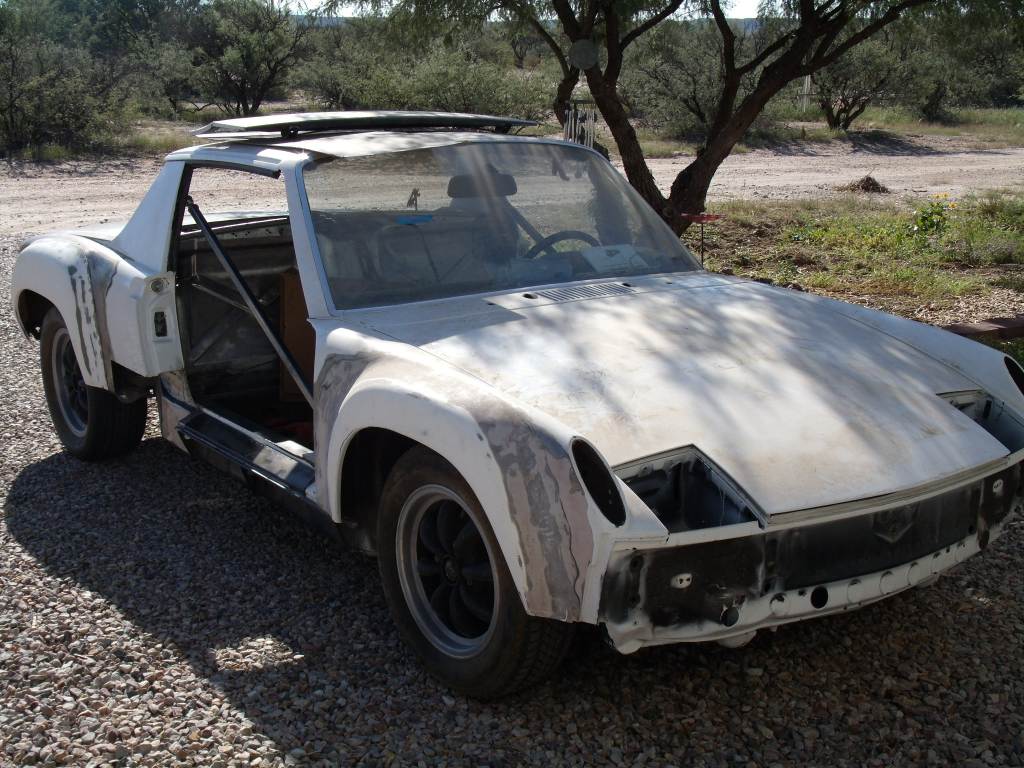
Mike, yea I know what you mean. Unfortunately the car is still in this condition.
I found the break-out box you mentioned for the EEC-IV version on the SHO. I'll need to do some homework before buying one to make sure I understand how I can use it. Last FI I worked with was the MegaSquirt II on a stock 914. Tuning and diagnostics was easy when you can plug it into a computer and monitor data.
QUOTE(3d914 @ Jan 27 2013, 06:54 PM)
I found the break-out box you mentioned for the EEC-IV version on the SHO. I'll need to do some homework before buying one to make sure I understand how I can use it. Last FI I worked with was the MegaSquirt II on a stock 914. Tuning and diagnostics was easy when you can plug it into a computer and monitor data.
Buy it. Learn later. You may never find another.
In the manual it will tell you which test point to look at based on the trouble code. With a multi-meter, you just read the point. Based on the reading, it will recommend what the problem is. Sometimes you may have to look at multiple sensors.
Pretty easy really...
 When I was stumped working on my first V8 914 (Ford), My dad lent me his. I had the problem solved in minutes... I was young then so finding the money for the new ignitor was the hard part...
Not much going on recently. Was out visiting family last weekend - had a real nice trip. Been cold all week and working late so not planning to run the motor until this weekend. Here's the breakdown on what I need to do:
- Run engine at normal operating temp & give PCM a chance to learn
- Add some AutoRx or similar to help loosen potential stuck piston ring
- Check condition of plugs after engine run (and cool down)
- If no further codes, bring engine to normal temps & run cylinder balance test
- If valve noise continues on Cyl #3, perform tear-down and inspection of heads
Well got throught the first few items in the list, but no improvement inthe running condition.
- Run engine at normal operating temp & give PCM a chance to learn
- Add some AutoRx or similar to help loosen potential stuck piston ring
- Check condition of plugs after engine run (and cool down)
Been inspecting things as I tear the motor down. Checked all the timing points. Everything looks good. Chains are under tension. Cam shaft flats are vertical and rear index marks all line up with the top face of the head. The crank sprocket index lines up with the mark on the case. all looks good. So I know the poor running condition wasn't due to timing.
Found answers to a few other things while tearing down.
Also gutted the PS pump. I hate PS fluid - what a f#!%@# mess. I noticed that the bearing doesn't appear to be lubricated by the fluid, so I gutted the pumping cam and put it back together. I'll just cap the threaded opening to keep crap out and be good to go.
Next up is the heads.
Found answers to a few other things while tearing down.
- Located leak at end of back head. Turned out the Cam Sensor seal was leaking.
- Of course the PS bracket puddled the oil so I couldn't ID the leak.
- The PS bearing functions OK, but looks rough and appears to leak a little (but might be from Cam seal). If I can get a replacement I will otherwise I'll leave it.
Also gutted the PS pump. I hate PS fluid - what a f#!%@# mess. I noticed that the bearing doesn't appear to be lubricated by the fluid, so I gutted the pumping cam and put it back together. I'll just cap the threaded opening to keep crap out and be good to go.
Next up is the heads.
OK, here's what I got done so far on the right head.
Here's some pics.
Cyl#1 intake seals with valves - haven't pulled them yet.
Click to view attachment
Cyl #1 & 2 Pistons
Click to view attachment
- Pulled the cams off the right head
- Pulled the valve locks, retainers, and springs
- Inspected the seals in place
- Cyl #1 exhaust seals are loose
- Cyl #2 exhaust seals are loose
- One of Cyl #3 exhaust seals is loose
- All intake seals are tight
- Visual inspection of the pistons
- All three pistons have oil in the valve recesses
- Piston walls don't appear to show any signs of honing
- Pistons walls are soaked with oil
Here's some pics.
Cyl#1 intake seals with valves - haven't pulled them yet.
Click to view attachment
Cyl #1 & 2 Pistons
Click to view attachment
Pulled all the seals on the right head and preparing to lap the valves. Once right head is done, will move on to the left one. Will get seals ordered shortly - so new seals all around.
Pics once the heads are refreshed.
Pics once the heads are refreshed.
OK, got the first six valves done on the right head. They really needed lapping. Guess I should of done this initially. Got some nice clean seats now. Had to post a pic.
Click to view attachment
Click to view attachment
Spent part of the weekend pulling the left head. Got all the valve hardware off. The exhaust seals were shot on this side also. Will get the valves lapped this week and be ready to thoroughly clean the heads this weekkend before reassembly.
Decided to remount the heads after installing seals to get compression for each cylinder. Will decide about pullling cylinders & rings based on that.
Decided to remount the heads after installing seals to get compression for each cylinder. Will decide about pullling cylinders & rings based on that.
Were your valve guides in good condition?
Guy
Guy
QUOTE(914GT @ Feb 18 2013, 04:48 PM)
Were your valve guides in good condition?
Guy
Guy, Yes, there was no "additional" air when I tested the intake pressure before tear down, and no noticable slop on any of the valves in the guides.
I'm still waiting for valve seals to arrive. Cleaned up the right head, and pulling the engine/tranny off the cradle so the block can be installed on an engine stand.
Click to view attachment
Click to view attachment
About all I got done this weekend was to clean up the left head. Got some sinus infection & its been slowing me down. The seals came in, but before I work on those I need to get the engine block up off the floor and onto a stand.
Finally pulled the tranny, clutch assy, and flywheel off.
Did notice on the flywheel that the starter teeth don't seem to be engaging fully - only about 1/4 the tooth. I'll have to contact Kennedy to see what they say.
Click to view attachment
Did notice on the flywheel that the starter teeth don't seem to be engaging fully - only about 1/4 the tooth. I'll have to contact Kennedy to see what they say.
Click to view attachment
Just an update. The tear down is proving to be a slippery slope. First bad valve seals - not too bad. Pulled pistons to check them - only a couple of partially stuck rings. Checked the ring gaps - way out of spec. So that means at least a new ring set.
Now I'll have to measure the cylinders to see if they're within spec or not - and may have to go over-sized. This is just too much fun - think I need a break!
Now I'll have to measure the cylinders to see if they're within spec or not - and may have to go over-sized. This is just too much fun - think I need a break!
Well you could always bring it up to Doc's machine shop in Tucson and simply write him a check
Guy, have you used them before? I may have to have the cylinders oversized. Got a micrometer on order so I won't know for a while.
Since my micrometer is on order, I decided to use the ring gap as a gauge for preliminary cylinder bore taper measurements. Took the top ring from piston #1 to use for all cylinders in three locations along each bore. I was also able to inspect the cylinders better with some daylight. I don't see any traces of cross-hatching in any of the cylinders (pics included).
Here's the preliminary taper results and pics.
Cylinder #1:
Click to view attachment
Here's the preliminary taper results and pics.
Cylinder #1:
- Position-A = .022
- Position-B = .0215
- Position-C = .0215
- Position-A = .023
- Position-B = .022
- Position-C = .022
- Position-A = .023
- Position-B = .022
- Position-C = .022
- Position-A = .023
- Position-B = .022
- Position-C = .022
- Position-A = .023
- Position-B = .0215
- Position-C = .022
- Position-A = .023
- Position-B = .022
- Position-C = .022
Click to view attachment
This is a "lo-fi" version of our main content. To view the full version with more information, formatting and images, please click here.