Well, I found out that Wurth's makes a flexible seam sealer that can be brushed or sprayed on to replace the old stuff here. Guess I'll visit the Bird site for some prices.
Back to work . . .
Full Version: 3D914s 914-6 SHO 3.2L v6
Progressing slowly.
Earlier this week I picked up all the pieces I needed for my rotisserie. I'm using the two engine stands method, with a support beam connected between them. I'll post assembly and parts pics after I finish cutting all the various sizes.
With my sons help, I pulled the gas tank out. Fortunately there was enough lose rubber fuel line to reach down and cut it without having to jack up the car and cut it from underneath. The partial metal/plastic fuel lines running through the car will get replaced with all metal fuel lines. I'll save this for when the car is on the rotisserie.
Click to view attachment
From there we removed the fresh air vents, motor and housing. There are some metal spring clips where the wire cables connect to the various vents (in red below). Care is needed to remove these without deforming or breaking them. On the left side, cables attached with small 8mm nuts, but on the right side the cable had a Z shaped bend that requires the spring clips, mentioned earlier, to be removed first.
Click to view attachment
During the process of removing all the venting in the front, it was necessary to remove the two small 90deg elbows located up underneath the cowl & behind the hood hinges. What was even more surprising is that I saw a round obstruction in each one. At first it looked like the back of a gauge of some kind. What kind of gauge would someone put in there?
With a little effort I was able to turn it around to look at the front, and to my surprise I see a tiny little speaker. Someone put a speaker (probably a tweeter) in each of the fresh air vent tubes. At first all I could do was laugh -
Click to view attachment
Then as I thought about it - it was actually quite creative. I'm not sure how well it would work, but it was certainly an unconventional idea.
After we had our good laugh, we continued to remove the windshield wiper assembly. All that was needed was to remove the two 22mm nuts at the wiper blade studs, and cut the rubber standoff plug that holds the center bracket to the firewall. It may be possible to remove the rubber standoff and keep it in tact, but with the dash in place it was difficult to see how it attached to the other side of the firewall. Since the nut was rusted on ours, we chose to cut the rubber and replace the whole piece.
Click to view attachment
Its seems like there has been little progress and things are moving more slowly than I would like.
I started on my rotisserie, then ran into problems with my air compressor. My suggestion for others taking on this kind of work - keep it simple and go with electric tools unless you already have a 4HP+ air compressor. Anything less will be marginal for this kind of work.
I was able to borrow a compressor from a friend - thanks Tim - and got all the pieces cut for the rotisserie. I was continually hampered by small things. First the compressor, then running out of cutting disks, yada yada . . .
I just have to accept that any custom project like this is going to require constant trips to the hardware, auto parts, paint & body stores - there is just no way around it.
Anyway, I did manage to start the welding on the rotisserie. I really enjoyed this. I've been reading about it, viewed a few videos, then just decided to go try it. I was amazed at how easy it was, and how much I enjoyed melting metal together.
Here's a picture of the first section I completed today. I just held it in place, but I'll be drilling holes so that it mounts through the bumper holes in the frame.
Right side
Click to view attachment
Left side
Click to view attachment
Its been a very satisfying day . . .
Might I suggest that when you encounter a rubber isolation mount, that you check price and availability first before cutting. Three that spring to mind are the wiper rack mount, the fuel pump mounts and the late engine mounts. In all cases they have simple nuts on the studs on each end.
Good tip - thanks Dave.
Even though I got a little zealous with the the welding and mis-welded a couple of pieces - I was able to cut them to the correct size. I feel like I have opened a whole new world of possibilities now that welding is available to me.
So here are some of my NEWBIE WELDING INSIGHTS . . .
Here's the rear mounting ass'y for the rotisserie.
Click to view attachment
I wanted to post some close-ups of the welds in stages of improvement, but this digital camera is not cooperating. With the auto-tint helmet I went from crooked welds to straight and can actually see before I get to the end of the piece.
Enough for the hot garage. Time to sit down and enjoy the rest of Father's Day.
So here are some of my NEWBIE WELDING INSIGHTS . . .
- Spend $50+ and get an adjusting auto-tint welding helmet. You can see your work before, during and after. Makes a HUGE difference.
- If there is light between the parallel metal pieces - its a pretty good change you'll blow through, even with lower settings. I ended up just doing spot welds up & down across the seam in a few spots. Worked much better.
- Relax and take a deep breath. Take your time. I get excited doing this and I have to keep forcing myself to slow down. This is just too cool.
Here's the rear mounting ass'y for the rotisserie.
Click to view attachment
I wanted to post some close-ups of the welds in stages of improvement, but this digital camera is not cooperating. With the auto-tint helmet I went from crooked welds to straight and can actually see before I get to the end of the piece.
Enough for the hot garage. Time to sit down and enjoy the rest of Father's Day.
Well I've got my new bumpers on. I always thought the 914 would make a great car for the Demolition Derby . . .
Front
Click to view attachment
Rear
Click to view attachment
I was planning to weld the support pieces onto the cross-piece but decided to use 1/2in bolts instead since this allows a little more flexibility. Just need to pick up the hardware later this evening when I go out get an electric grinder/cutter.
Waiting for my daughters to finish making their home-made pizza
then off to the hardware store.
I spent a couple of evenings this week getting the engine stands ready. I had the pieces already cut, but each one needed grinding to get rid of any variation in the mating edges. The stands are the 1000# variety from Harbor Freight. One is an older style and was taller, so I ended up with two different sized insert pieces.
Click to view attachment
The inserts do two things. THey raise the housing for the rotating flange to just over 36". Since the base is raised and the front wheels are mounted under the tubing this won't allow full 360deg rotation of the car body. That was intentional on my part. I wanted to keep the body as low as possible. To allow for full rotation, one would need to raise it another 3-4 inches. That would put the center axis at about 40 inches, and the portion of the car aobve the axis would be another 34 inches; giving a total of 74 inches of vertical clearance needed.
The second thing the inserts do is negate the 7.33deg angle designed into the vertical 3"x1.5" tubing. I cut the stand tubing 90 degs across its width, then cut the insert piece so that one side has the 7.33 deg cut, and the other is a 90 deg cut. When welded together, this will make the cylindrical housing axis horizontal.
Here are the two stands. I'm not going to bother with painting - just keep them functional.
Click to view attachment
Click to view attachment
The inserts do two things. THey raise the housing for the rotating flange to just over 36". Since the base is raised and the front wheels are mounted under the tubing this won't allow full 360deg rotation of the car body. That was intentional on my part. I wanted to keep the body as low as possible. To allow for full rotation, one would need to raise it another 3-4 inches. That would put the center axis at about 40 inches, and the portion of the car aobve the axis would be another 34 inches; giving a total of 74 inches of vertical clearance needed.
The second thing the inserts do is negate the 7.33deg angle designed into the vertical 3"x1.5" tubing. I cut the stand tubing 90 degs across its width, then cut the insert piece so that one side has the 7.33 deg cut, and the other is a 90 deg cut. When welded together, this will make the cylindrical housing axis horizontal.
Here are the two stands. I'm not going to bother with painting - just keep them functional.
Click to view attachment
I guess I forgot to add the info on the rest of the parts for the rotisserie. I spent $50 for the one stand, and $30 for the older one IIRC. All the steel totaled to around $65, so my total for materials was under $150.
Click to view attachment
- Two 1000# engine stands
- 3x1-1/2 x 8" x .12 steel tubing for engine stand inserts
- 1-3/4 x 1-3/4 x 144" x .09 steel tubing for all other pieces
- 2 x 2 x 12" x .09 steel tubing for 4-3" sleeves
- 2 x 2 x 12" x .09 steel angle for 2-6" flanges on cross pieces connecting both stands
- 1-1/2 x 1-1/2 x 102" x .08 steel tubing for cross pieces connecting both stands
Click to view attachment
Today I was able to complete the remaining steel support that connects the two engine stands. Once I got the measurements right & cut it, I needed to grind it to fit the two angles used to bolt it to the stands.
It was then welded to the the angle pieces. The angles can then be removed along with the support until the car is up on the stands, then re-attached.
Click to view attachment
Click to view attachment
It was too hot to do much else. I spend all day in the sun working, so I can only last a few more hours in the garage with no cooling. Then its a cold refreshing shower and I've got my second wind.
Wednesday I hope to get the car up on the rotisserie. Can't wait.
QUOTE(3d914 @ Jun 23 2008, 07:55 PM) 
It was too hot to do much else. I spend all day in the sun working, so I can only last a few more hours in the garage with no cooling. Then its a cold refreshing shower and I've got my second wind.
Wednesday I hope to get the car up on the rotisserie. Can't wait.
I got a large fan for my garage. It's about 3 ft in diameter and moves a lot of air, but doesn't blow you out of the garage. Well worth the money.
Bryan,
Where did you get it?
Where did you get it?
You can get high CFM fans like that at Home Depot. They are not too expensive. I'm going to buy one to use for ventilation on the next car I paint.
QUOTE(3d914 @ Jun 25 2008, 04:16 PM)
Bryan,
Where did you get it?
I bought it used from my neighbour. It's basically like This. Home depot has some pedestal fans, but I don't think they are as robust as this one--it's pretty hefty.
Thanks Jim & Bryan,
That explains why I haven't seen them - I rarely frequent the Home Depot. I'm more of an Ace Hardware kinda guy. I'll have to check them both out.
Well I got the car up on the rotisserie tonight. A friend of mine came over and helped. It went pretty well except that I need to build a small (12-18" high) extension for my ATV lift so that I can jack a greater distance. I'm not fond of using wood blocking - so it will give me chance to develop my welding skills a little further.
Click to view attachment
SOo now I'm ready to get back on the body work and get the flares finished and the rear trunk stripped and primed.
May have some exciting news tomorrow regarding power-train. Stay tuned!
Today I drained the brake fluid and inspected the disks & calipers. Three of the four disks are under-sized, so I'll be replacing them.
The front calipers are getting replaced with BMW 2002 4-piston calipers, and the backs I'll rebuild and reuse.
I'm continuing to strip paint in the rear trunk. I had no idea this would be such a slow process. It takes several applications with 15-20 minute wait between apps. And of course you all know how flat and smooth the trunk is in a 914 - NOT!
DID I MENTION . . .
I found a 3.2L V6 SHO motor to rebuild for $200.00. That's complete from exhaust headers to intake. All I'll need to add is the ECM. The gentlemen that let me come over to measure the SHO engine had one he had pulled from a local junk yard. I'll start with an inspection of the crank and mains, water pump, and rod bearings. If all that looks good I'll proceed with cleanup and the rebuild. I'll get some pics next week when I'm over there.
Sweet!!!! SHOpics please!
Hey Bryan - I can hardly wait to get started on this engine. Should make some basic progress next week. And I'll get pics also.
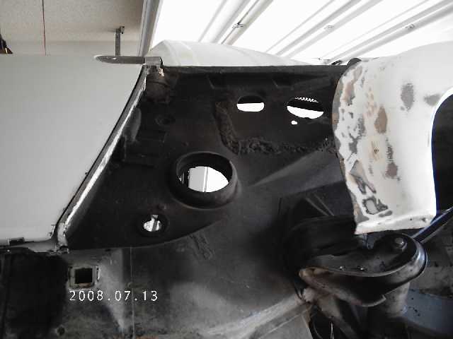
Well I spent MORE time in the trunk stripping paint - and I'm still not finished. In between applications of paint remover I was working on the engine bay. I removed a metal plate that someone installed as a band-aid for the "hell-hole". SO it looks like I'll be hunting for the pieces to fix this. Battery tray was garbage, and I knew there was some work to do there since the rust was obvious in spite of the band-aid.
Click to view attachment
I'll likely relocate the battery, but I may end up with more room in the engine bay than any where else. And if it stays in the engine bay, it may still get relocated to a lower, more stable location.
I also removed the rubber liner behind the back-pad. If you're interested in saving this liner, the best way to remove it is with a chisel or stout paint scraper. That way you can get behind the pad everytime you encounter cement, and free it before it tears the pad.
Everything else looks clean except for the lower right corner where the "hell-hole" came through the firewall.
Click to view attachment
Well, the pretty pics of the engine will have to wait a while. I got the engine torn down, but found that the crank was broken just behind the front connecting rod. I've got a replacement crank and rod, but that means a complete tear-down of the engine to replace the one rod, inspect/replace rings, etc, . . .
I'll get some staged pics as soon as possible.
I'll get some staged pics as soon as possible.
Well the fun continues . . .
Engine - Had the block magna-fluxed and found a crack by one of the upper core plug holes. Fortunately Tom had another block, so progress is continuing. I'll get some pics once I get the heads back on.
Body - Took some extra time off over the holiday, but I didn't get to use all of it working on the body since I had a side project that came up. I did manage to get the right rear inner part of the fender/flare glassed. I used three layers of material. I'll clean up the edges and cover the whole inner wheel well with some under-body sealer. Pic inside the wheel well. THe black behind the FG is the factory paint. I stripped a couple inches down to metal, but ran into the painted area a little.
Click to view attachment
I also got most of the rubberized seam sealer off in the rear trunk. I tried the torch method, but it still required as much scraping. I found that a good chisel was an excellent way to get under the sealer so I could remove it in bigger chunks. It actually turned out to be faster also. A wire wheel came in handy for some of the small corners - but I found that unlike the scraping (with chisel or paint scraper), which left the factory primer, the wire wheel stripped clear down to the bear metal. Even though this will all get primer, I like the idea of putting new seam sealer on top of the old primer - as the factory did.
I'll get some more pics when I get the trunk completely stripped and get some new batteries for the camera.
This week I've been working on the engine. It works out better to spend time on the engine for a few hours in the late afternoon and save the body work for the weekend.
The engine is coming along. Tom's been a big help getting things squared away. We've got a good block, crank, rods, pistons, heads, intake, etc. I've started cleaning and some assembly. I'll begin prepping for paint next week.
There are two complimentary colors on the car in addition to the Orange. When racing the GT's the factory would color code the bumpers so that each car could be identified easier when viewed head-on. I plan to apply this to my car and use yellow and red for the two halve-colors on the front & rear bumpers. These are the same colors I'll use for the engine.
Here's a quick image my son modified for me to illustrate. The block and oil pan will also be yellow to match the intake. I wanted to avoid black since the engine cover is a black mesh. This way the colors will be more apparent behind the black grill.
Click to view attachment
Can't wait to get the engine painted and together.
I worked on the left rear quarter today. I needed to get the access metal behind the flares trimmed out. To do this I went ahead and trimmed the adjacent area where the new body panel goes in.
I used my 4in cutter to rough-cut the area.
Click to view attachment
then followed with my Dremel tool to get a nice clean cut.
Click to view attachment
I was able to pry off the sheet metal under the flare without damaging the flare at all. Since the sheet metal was a thin strip a couple inches wide, it flexed quite easily and there was no real pressure on the FG flare. Here's a shot from behind the flare. Now I just have to grind off the adhesive on the back side of the flare before applying new adhesive.
Click to view attachment
All that was left was to trim the access sheet metal behind the flare. I use my Dremel tool for this since it provides good control and I don't have to worry about damaging the flare. I use the big cutter to remove the strip of sheet metal once it reaches 18in or so. Here's the trimmed underside ready to be prepped for fiberglass.
Click to view attachment
It's getting there - slowly but surely.
Currently I'm working on three things at the same time.
The Body work - getting ready to attempt the butt-weld of the new piece, but I have several things to complete before then . . .
This should keep me busy for the rest of the summer. Stay tuned boys & girls - photos are on their way . . .
The Body work - getting ready to attempt the butt-weld of the new piece, but I have several things to complete before then . . .
- Have to strip the old paint off the replacement piece
- Need to test my welder to see how well it does with the 16-ga sheet-metal
- Find some good butt-weld clamps (any suggestions?) and an aluminum blocking plate.
- Overlay & trim the new piece to size.
- Once welded in place, I'll fiberglass the entire back-side joint of the flare/sheet-metal
- Cleaned and painted the oil pan
- Cleaned and painted the block
- Cleaned the heads and valve covers
- Have to paint the valve covers
- Need to modify and weld the intake manifold
- Need to clean and paint the intake manifold
- Need to clean and paint the intake runners
This should keep me busy for the rest of the summer. Stay tuned boys & girls - photos are on their way . . .
Well I've managed to get the transaxle completely cleaned. I used POR-15's Marine Clean. At a 1:1 dilution with water it does an amazing job. I use both nylon & soft-metal brushes to loosen the grease and grime, then just rinse with water. Too easy.
Here's a before and after.
Click to view attachment
Click to view attachment
I ran out of POR Paint Stripper and Marine Clean, so I think I'll work on painting the valve covers and modifying the intake manifolds this weekend. The tranny inspection can wait till next week.
Stay cool
Here's a before and after.
Click to view attachment
Click to view attachment
I ran out of POR Paint Stripper and Marine Clean, so I think I'll work on painting the valve covers and modifying the intake manifolds this weekend. The tranny inspection can wait till next week.
Stay cool
Did anyone else notice that this car has holes for the factory six oil tank???
Are you sure this car is not a lost six????
This is a cool project.. I like watching the unconventional done.
Are you sure this car is not a lost six????
This is a cool project.. I like watching the unconventional done.
Clay,
The previous owner converted this original 1.8 to a six - then it was stolen and the thieves removed the six and left the rest. PO put the 1.8 back in and later sold it to me.
The previous owner converted this original 1.8 to a six - then it was stolen and the thieves removed the six and left the rest. PO put the 1.8 back in and later sold it to me.
QUOTE(3d914 @ Jul 25 2008, 04:49 PM)
Clay,
The previous owner converted this original 1.8 to a six - then it was stolen and the thieves removed the six and left the rest. PO put the 1.8 back in and later sold it to me.
If all the holes for the tank and the motor mounts are there, why not make it a six?
Not critizing your work, just asking. It would be a hell of a lot simpler.
Clay,
I just wanted to do something unusual & non-Porsche. I had three nice cars already that were kept Porsche, but this time I wanted to try something different - hence my choice to go SHO.
Speaking of which - I worked on the valve covers & intake manifold today. The valve covers just needed minor cleaning and light sanding. They have a coating on them (I don't think it anodizing), so I need to find out if this can be painted on or not.
Started to disassemble the intake manifold. Here's the beast with most attachments.
Click to view attachment
I need to remove several bosses that I will not be using and will help reduce the length for a better fit. The first to go is the DIS flange.
Click to view attachment
To remove it I first cut off large sections top & bottom, then started to grind and file down close to the desired shape. I continued to rough the shape with a file, then did some sanding with 60 & 100 grit. The hole will get welded in and then I will finish it all off. But there are several other smaller flanges that need to come off also.
Click to view attachment
I like aluminum . . .
Now that the Valve covers are dry, here's how they look in Ford Red (Duplicolor 500deg paint)
Click to view attachment
and
Click to view attachment
purty . . . (but not the best JPEGs)
Click to view attachment
and
Click to view attachment
purty . . . (but not the best JPEGs)
You know, I hate to meddle with your paint choices after you've already started but....
That intake looks bitchin in raw Al. Reminds me of something you would see on a vintage aircraft. And, I would do the valve cover in red wrinkle coat. Like the Maserati Spyder...
Click to view attachment
That intake looks bitchin in raw Al. Reminds me of something you would see on a vintage aircraft. And, I would do the valve cover in red wrinkle coat. Like the Maserati Spyder...
Click to view attachment
Jason,
I agree - that wrinkle affect looks cool. I'll have to save that idea for next time though - too far along to backup now.
I agree - that wrinkle affect looks cool. I'll have to save that idea for next time though - too far along to backup now.
Still workin on the intake manifold. I removed the intake runners and noticed that they would look much better with the casting seams removed. So I dug out the Dremel with the course sanding disk and went to work. Once I got the seam flat I used a file to feather and contour.
Went from this . . .
Click to view attachment
To this . . .
Click to view attachment
I still have to have these media blasted to remove the paint, but I have done a little sanding on them. The paint on these is thicker than the paint on the valve covers - for whatever reason.
Went from this . . .
Click to view attachment
To this . . .
Click to view attachment
I still have to have these media blasted to remove the paint, but I have done a little sanding on them. The paint on these is thicker than the paint on the valve covers - for whatever reason.
When I was in the SHO club there were some guys who had theirs polished... talk about a dramatic effect.
Definitely. Here are some examples . . .
SHO Bling . . .
Click to view attachment
Click to view attachment
Click to view attachment
Click to view attachment
Click to view attachment
Click to view attachment
Click to view attachment
Click to view attachment
Click to view attachment
Purty
SHO Bling . . .
Click to view attachment
Click to view attachment
Click to view attachment
Click to view attachment
Click to view attachment
Click to view attachment
Click to view attachment
Click to view attachment
Click to view attachment
Purty
OK, I know there hasn't been much action here lately . . .
because its tooo dannggg HOTTTTT.
I am getting a few things done on the weekends. Pics to come when I have something together.
Stay cool!
because its tooo dannggg HOTTTTT.
I am getting a few things done on the weekends. Pics to come when I have something together.
Stay cool!
Good thread, lots of hard work, I don't know how you can work in the heat. I am retired and last summer I would work early in the morning till about 12 noon then clean up and eat and take a siesta and go back out at 7pm and work till 12 or 1 am. It worked pretty well except that you gotta have good lights and the painting must be in the early morning or it will get bugs in it. I also use a few big fans. Of course the fans gotta be off to weld.
Practise a lot with the scrap body metal before you try to put the repair panel in. You said the body metal is 16 ga. but I'm pretty sure it's thinner than that. It's probably 18 ga. Spot weld about 1 inch apart and keep going around the panel if it gets too hot to touch do something else and let it cool. You can buy the little butt weld gadgets at HF. I use a thick piece of copper to back the weld up if I can get it in position. Eastwood has a magnetic copper strip but it's not cheap.
My experience with pop rivets are they will show up later as little circles no matter what you put over them. After you get the fiberglass bonded to your satisfaction, drill them out and fill the area over with fiberglass strand. I haven't tried it but the product Kitty Hair, made by Evercoat, is a bondo type putty with fiber strands in it. There is also one by the same company that has short strands it probably will be easier to use, the long strands are harder to work with. They are both waterproof. I use them both but I haven't had to deal with pop rivets lately.
On the rotisserie I thought the practice was to brace the door gap to keep the tub from sagging as now the support is on the very ends not at the suspension where the tub was designed to be supported. I guess if the door gaps haven't changed it's ok, although it would be something if the fenders are stressed at the front and rear and you do all the body work and they relax when you take it off the rotisserie.
My experience with painting aluminium motor parts is that unless they are bead or sand blasted and painted with a epoxy paint it doesn't stick very well.
Good luck you are really working hard, I'm sure you will be proud of the finished product.
Isn't car life full of lessons?
Charlie,
Thanks for the insights. Things have been progressing very slowly the last few weeks. On top of the heat, I now spend 4 hours at school a couple of nights, and reading/homework a couple more nights. But at least its time spent indoors - cool!
You're correct on the sheet metal - mostly 18 & 20ga in a few spots.
I've been trying to finalize my trunk and get it at least primered. The shop doing the final paint work suggested a self-etching primer to protect the bare metal. So now that I have most the paint off, I'm just cleaning up some areas of surface rust in the trunk, prepping down to bare metal, cleaning & treating with Metal Ready, then shooting with a couple lite coats of primer. Took eleven hours over two days last weekend just to get 1/3 of the trunk done.
Once I get the entire trunk to that point, then I'll move on to the sheet metal. I bought some other replacement/add-on panels, so I've got to start focusing on welding again. And then there's the hell-hole that I have to investigate.
Regarding the rotisserie; I still have my doors installed in order to maintain integrity. I also left the suspension in tact so that I can lower it as needed to do a couple of body cuts that shouldn't be done in the air.
I managed to get the aluminum manifold welded, so now I just need to finish up the metal work, blast it and get it ready to paint.
No work on the teener this weekend though - my son is in for the weekend from college - so I get to spend some time with him & working on his car.
PS: You're right about the lessons. I keep looking for them.
School Schmool... get ta work on that car. I want a ride! 
OK, finally the engine is going together. He's where my list is at compared to a couple months back.
Engine rebuild . . .
To say I'm glad to have reached this point is an understatement. I'm glad I'm not on a schedule.
Here's a picture of the current status. Once I find the head bolts I can continue . . .
Click to view attachment
Engine rebuild . . .
- Cleaned and painted the oil pan
- Cleaned and painted the block
- Cleaned the heads and valve covers
- Cleaned and painted the valve covers
- Modified and welded the intake manifold
- Cleaned and painted the intake manifold
- Cleaned and painted the intake runners
- Had the heads professionally cleaned and decked
- Replaced numerous freeze block plugs
To say I'm glad to have reached this point is an understatement. I'm glad I'm not on a schedule.
Here's a picture of the current status. Once I find the head bolts I can continue . . .
Click to view attachment
OK, got some more done on the engine this weekend - thanks Tom!
Heads are on & valve covers are just sitting there waiting to put the seal/gasket on.
The crank position sensor is mounted and gapped.
A remanufactured waterpump Tom had available is also installed, along with the main tubing and housings for the head cooling.
Here are the pics so far:
Click to view attachment
Click to view attachment
Purtty,
Did you swap in 3.0 cams?
Wow, that's a tall oil pan. You may need to shorten it. Have you test fit this in the car? Nice looking engine! 
![popcorn[1].gif](http://www.914world.com/bbs2/style_emoticons/default/popcorn[1].gif)
No 3.0 cams. I think the stock 3.2 is going to be more than enough to start with. And I can always upgrade - right?
I've done a test fit via CAD. The oil pan is low, but it won't sit more than 1/2" below the bottom of the rear firewall. You can see my layout on a previous page.
Once I get the intake on it will look even bigger. Once engine is running, I'll have to pull the intake off again to get the engine in from underneath, then install the intake from the top.
It'll be interesting . . .
OK - latest progress.
The engine build continues. Did a valve-adjustment on new years eve, and have numerous plastic covers cleaned, painted, and ready to install. New engine pics coming when I get it all buttoned up.
Next issue I've been playing with is the intake. The huge, but cool, intake manifold on the SHO requires an equally large throttle body that is preceded by a MAF sensor.
So the dilemma for me has been how to route the intake air from the engine lid to the throttle body without giving up my entire trunk. Here's a couple of things to keep in mind:
Over the Top
This method routes the intake from each side of the engine lid, through filters, then back up and over to the center, where they meet at the MAF sensor, then curves down to the throttle body.
Click to view attachment
Click to view attachment
Side Run
This method routes the intake from each side of the engine lid, through filters, then directly rear through the trunk wall, over to the center and to the MAF sensor, then slightly up and into the throttle body.
Click to view attachment
Down the Middle
This method requires a custom pedestal in the center to mount a wing. The pedestal will house the air filter and box to blend to the 3.5 inch outlet needed on the input side of the MAF sensor. The intake and MAF will route directly down the center into the throttle body. Most of this should stay hidden under the trunk lid, although a custom cover will still be needed for the throttle body itself.
Click to view attachment
Thoughts? Comments?
The engine build continues. Did a valve-adjustment on new years eve, and have numerous plastic covers cleaned, painted, and ready to install. New engine pics coming when I get it all buttoned up.
Next issue I've been playing with is the intake. The huge, but cool, intake manifold on the SHO requires an equally large throttle body that is preceded by a MAF sensor.
So the dilemma for me has been how to route the intake air from the engine lid to the throttle body without giving up my entire trunk. Here's a couple of things to keep in mind:
- This is a custom 914, not a restoration!
- Throttle body points to the rear and extends slightly above the rear trunk lid. A fiberglass cover will be made for this.
- The inake diameter into the MAF sensor is 3.0 inches
- The output diameter of the MAF sensor is 3.5 inches.
- I plan to change the trunk hinging so trunk opens from the front.
- I don't want to loose the trunk completely. This still needs to be a weekend cruiser.
Over the Top
This method routes the intake from each side of the engine lid, through filters, then back up and over to the center, where they meet at the MAF sensor, then curves down to the throttle body.
Click to view attachment
Click to view attachment
Side Run
This method routes the intake from each side of the engine lid, through filters, then directly rear through the trunk wall, over to the center and to the MAF sensor, then slightly up and into the throttle body.
Click to view attachment
Down the Middle
This method requires a custom pedestal in the center to mount a wing. The pedestal will house the air filter and box to blend to the 3.5 inch outlet needed on the input side of the MAF sensor. The intake and MAF will route directly down the center into the throttle body. Most of this should stay hidden under the trunk lid, although a custom cover will still be needed for the throttle body itself.
Click to view attachment
Thoughts? Comments?
Side = Clean
QUOTE(Eric_Shea @ Jan 11 2009, 10:56 AM)
Side = Clean

A lot of time has gone by, but progress continues slowly. Here is the pre-assembly of the famous SHO Intake Manifold. I've been taking my time making sure everything is fitting together properly.
(Here are two pics. For some reason the yellow gets washed out in the sun)
Click to view attachment
Click to view attachment
Since the wiring harness sits under the intake between the fuel injector rails, I have a lot of work to do on the harness. I got it cleaned up & removed all the old dried out tape and insulator. Some lines will need to be extended for my application so all that will get done before the test run.
Click to view attachment
More to follow . . .
I think the down the middle is the most direct, and elegant approach. with a minimum of bends you dont have to worry about any pesky flow dynamics, and you know it will be a more laminar charge. also if the pedistal faces fron, it will be RAM AIR!
Mark,
Sorry to see you're selling your project. I'll be relying on your current project thread for some insight into the typical body mods (hell-hole, flare fit with rockers & valances, etc). Don't stray far from the group - gotta keep that 914 fever!
Best of luck,
Sorry to see you're selling your project. I'll be relying on your current project thread for some insight into the typical body mods (hell-hole, flare fit with rockers & valances, etc). Don't stray far from the group - gotta keep that 914 fever!
Best of luck,
This is a "lo-fi" version of our main content. To view the full version with more information, formatting and images, please click here.