Full Version: 1973 2.0L Rustoration
I've often found rust holes after the fact when doing engine tin. That's one of the reasons our shop won't do outside parts for a fee. Too many little gotchas that can triple the time you can charge for.
QUOTE(mepstein @ Nov 29 2019, 04:32 PM) 
I've often found rust holes after the fact when doing engine tin. That's one of the reasons our shop won't do outside parts for a fee. Too many little gotchas that can triple the time you can charge for.
@mepstein
It all went pretty well on the whole. Only once piece out of many, so, no worries.
I spent a lot of time welding cracks and straightening before I sent it out. Speaks more to my lack of quality control than the powder coater's. He probably didn't even see it when suited up in the blast booth and depending on the lighting, may not even have seen it when applying the powder.
Doing retail repair work is definately a risk. Sort of explains why so many shops (not just yours) don't do outside work anymore. I worked retail in college. You get some dicey characters!
Due to holiday's and work it seems like I haven't been making much progress. Last weekend was largely sent with the remnants of the 2.4L CIS & intake system tying to first get it taken apart so it fits in smaller boxes and then to determine what is salvageable.
Today, I spent a little time today messing with Ben's DIY oil tank kit.
Fit up and laser cutting are top notch. Unfortunately my welding technique doesn't quite lend itself to the nice, neat, uniform stack of dimes look. Functional -- yes. Pretty -- No.
Maybe someday.
Anyway, here are a couple quick pictures of the work so far.
Click to view attachment
Click to view attachment
Click to view attachment
@superhawk996
The top baffle needs 2 holes in it.. 1 for the filtered return oil to remove air from the oil and the. One for the oil filler neck/dipstick area..
The top baffle needs 2 holes in it.. 1 for the filtered return oil to remove air from the oil and the. One for the oil filler neck/dipstick area..
QUOTE(mb911 @ Dec 7 2019, 10:06 PM)
@superhawk996
The top baffle needs 2 holes in it.. 1 for the filtered return oil to remove air from the oil and the. One for the oil filler neck/dipstick area..
@mb911
Yup. Waiting on that sweet Black Friday group buy of GT filler necks to arrive.
 Easy to burn in the holes by blowing out the Aluminum screen with the TIG Electrode.
 Certainly appreciate the reminder though. I'm still playing with the best way to do the internal oil lines.
I think I also need to get an oil filter console in my hands before I do that. I'm tempted to do a light surface cut on the big console disk to make it perfectly flat. However, that needs to be done after all backside welding is complete otherwise the welding will warp the flatness of the disk when I weld on the back side return lines.
I'd rather do that machine work before I have a fully assembled tank.
Probably overthinking this since I'm betting your intent was that this could be assembled without the need for any machine work under the assumption that the console 0-ring will accomodate any minor unflatness.

QUOTE(Superhawk996 @ Dec 8 2019, 07:03 AM)
QUOTE(mb911 @ Dec 7 2019, 10:06 PM)
@superhawk996
The top baffle needs 2 holes in it.. 1 for the filtered return oil to remove air from the oil and the. One for the oil filler neck/dipstick area..
@mb911
Yup. Waiting on that sweet Black Friday group buy of GT filler necks to arrive.
Easy to burn in the holes by blowing out the Aluminum screen with the TIG Electrode. Certainly appreciate the reminder though. I'm still playing with the best way to do the internal oil lines.
I think I also need to get an oil filter console in my hands before I do that. I'm tempted to do a light surface cut on the big console disk to make it perfectly flat. However, that needs to be done after all backside welding is complete otherwise the welding will warp the flatness of the disk when I weld on the back side return lines.
I'd rather do that machine work before I have a fully assembled tank.
Probably overthinking this since I'm betting your intent was that this could be assembled without the need for any machine work under the assumption that the console 0-ring will accomodate any minor unflatness.
Correct.. The o ring does a pretty good job of sealing..
QUOTE(mb911 @ Dec 8 2019, 10:56 AM)
Correct.. The o ring does a pretty good job of sealing..
@mb911
Thanks Ben, appreciate the oversight. You have some awesome products! I'm absolutely amazed at how little tweaking it took to get the console disk, and the fitting bungs to fit. The laser cutting is nearly spot on.
Part of my rationale for doing this as DIY in the first place is to get more seat time with the welder, it's the only way to improve my Aluminum welding consistency.
QUOTE(Superhawk996 @ Dec 8 2019, 08:06 AM)
QUOTE(mb911 @ Dec 8 2019, 10:56 AM)
Correct.. The o ring does a pretty good job of sealing..
@mb911
Thanks Ben, appreciate the oversight. You have some awesome products! I'm absolutely amazed at how little tweaking it took to get the console disk, and the fitting bungs to fit. The laser cutting is nearly spot on.
Part of my rationale for doing this as DIY in the first place is to get more seat time with the welder, it's the only way to improve my Aluminum welding consistency.
Practice makes perfect
Shifted gears a little bit as I work to clean up the garage and get rid of parts that I've been tripping over for months.
Goal is to get ready to get back to doing chassis work.
I've had a chunk of donor sheetmetal sitting on the floor that will be needed to fix the driver side fender inner to floor pan area that is rusted out.
Here is the starting point.
Click to view attachment
This piece of sheetmetal that holds the pedal boad is basically completely gone at the bottom on my car. This donor part is a good start but will still need some TLC to get it ready but it's better than trying to fabricate from scratch.
Click to view attachment
And here are all the parts discected. Much easier to store under a bench and out of my way for now.
Click to view attachment
Spot weld hell...  I feel for you, brother.
I feel for you, brother.
@mb911
Ben, would you be able to post a picture of how you do your tank internals?
Did some more work today on the oil tank internals the plumbing to feed the filter was straight foraward.
Click to view attachment
But since I don't have a GT filler neck in hand yet, I'm not sure which side the dip stick tube runs toward. Right, left, or maybe right down the center. The only picture i have of it is ambigious.
Click to view attachment
I'd prefer to route the filterd oil outlet to the right side to get more time with the screens to deairate the oil.
Click to view attachment
But I'm not sure if this routing will interfere with the dipstick tube.
The other option is to creat a U-turn back to the other side like the OEM tank but I'd rather not have to do this.
Click to view attachment
Any photos of your internals and/or a confirmation on which side the GT filler dipstick runs to would the awesome.
Perfect. Thank you Ben. Roughly aligns to what I wanted to do. I'll keep filtered oil exit closer to the vertical screen / baffle.
I dont know your 911 2.4 plan, but the 2.4 cis intake ports are tiny..Ollies gonna bore em out ??
Also as you did on the type 4sale case is what I do to the 2.4 cis inj. ports press in a shaft and weld the the top..when porting , smooth transition...lots of irons in the fire..

Also as you did on the type 4sale case is what I do to the 2.4 cis inj. ports press in a shaft and weld the the top..when porting , smooth transition...lots of irons in the fire..
@superhawk996
Make sure the mesh is at the exit of the bypass and extends 4-6 inches from there.. The idea is to remove the air bubbles from the oil.. Thats also the plan with the vertical baffle..
Ps I decided to make more tanks.. I just ordered more laser cuts..
Oh and pss.. I just hit my 4 year anniversary on my build..
Thanks for the updates, great thread.
QUOTE(sixnotfour @ Dec 14 2019, 02:12 AM)
the 2.4 cis intake ports are tiny..Ollies gonna bore em out ??
 I don't see port size (or HP) as a measure of my manhood.
 I'm still deciding since 2.4L's are a bit of an odd bird. The valves are all 46mm/40mm for T, E, and S. The 2.4T heads have a 33mm exhaust port which is right between the E (32mm) and the S (36mm) so I'm not too worried about exhaust port size.
 The intake is a 30mm port which is 2mm smaller than most of the earlier heads at 32mm and about 36mm for the S variants.
Where it gets interesting is that a 2.4LT variant is 140 HP & 148.5 ft*lb of torque @ 4000. the 2.4L 911E is 165 HP@6200 & 151 lb*ft@4500 rpm.
So what is the take away? Remember the formula (RPM * T) / 5252=HP. So the only way the E has an advantage is that it makes about the same torque but up to higher RPM's.
The small 30mm intake port keeps flow velocity high which is a good thing at lower RPM's (i.e. good in town driveability). What it doesn't do is breath as well at the high RPM's but let's be honest, how often are you driving at 6200 RPM in a daily driver? When I had my Miata my daily goal was to hit redline (7200) at least once a day with it but it was only a short temporary burst here and there when accelerating. Never was able to drive there for extended periods of time.

I'm tempted to stay at 30mm in the short term and see how I like it. Since want to go to ITB's and modern FI I think some breathing capability will open up just by losing the long 2.4L CIS runners. But that will also degrade some of the low end torque as the runner length diminishes with ITB's. Or, it may lean in favor of more RPM but at lower torque which could end up being a wash. They can easily opened up at any time if I don't like them.
The bigger problem is PMO ITB's only have 34mm as their smallest port.
I see no need for 34mm ports with a 2.4L. From what I see online, I'm a bit worried that I'll have to do my own ITB's, modify PMO's, or maybe fabricate some sort of Plenum and runner system from the 2.4L CIS runners 
At this point Ollies hasn't even called to discuss so I'm still deciding.
QUOTE(mb911 @ Dec 14 2019, 10:20 AM)
For anyone cosidering Ben's tanks, his welded and assembled tank is a great value.
Lot's of time fitting, welding, etc. go into putting this together from scratch and that is by no means a reflection on the materials. The laser cut parts are great. The fit is very close. But fitup and tweaking is just part of the metal fabrication game! For me I'm a automotive mascochist (why else would anyone have a 914?) and love doing fab work and wanted to spend more time with my welder practicing aluminum welding so it is awsome.
 But, I assure you, the price delta between DIY and finished product is well spent . . . just install and go your merry way!
I am loving this thread. Especially your copper topped welding table - that rocks!
QUOTE(TravisNeff @ Dec 14 2019, 12:04 PM)
I am loving this thread. Especially your copper topped welding table - that rocks!
Thank you.
 It makes life so much easier for welding.
 Last weekend I finally got fed up and tired of reconnecting my welding ground from the table top to the my vise. Sometimes it's just easier to use the vise to hold somthing when welding.
Side project was to cut another piece of coppper and extend my copper top under the vise, TIG'd the copper sheets together and then put the vise back on top. Ta da! No more need to keep moving the ground cable back and forth.
The copper bench top is also nice because it is soft and friendly to machined surfaces that sometimes get placed on it!
Just priced out copper plate what thickness are you using? And what are you backing it with, wood I am guessing as you had a grounding issue with the vice.
what thickness are you using? And what are you backing it with, wood I am guessing as you had a grounding issue with the vice.
QUOTE(914forme @ Dec 14 2019, 04:41 PM)
Just priced out copper plate
what thickness are you using? And what are you backing it with, wood I am guessing as you had a grounding issue with the vice.@914forme
Its over wood but copper is such an awesome conductor of heat it pulls heat away from hot spots I've never had any issues with scortching the wood below even with an Oxy-Acetylene torch. Doing TIG or MIG is a complete non issue since the heat is so focused.
Just measured it - about 0.060". It will be spendy but I've had this piece for over 15 years now. It is sort of a one time in a lifetime purchase. It doesn't wear out. The piece on my bench is structural copper (like for roofing) which is cheaper. I don't remember the material specification. Be sure they aren't quoting you oxygen free copper (OFC). There is a HUGE difference in price difference.
Ask me how I know. Norton Copper Cafe tank and rear cowl/oil tank has to C10100 (99.99% pure) OFC to avoid having weld contamination and porosity. One of these days I need to get this project restarted.
Click to view attachment
Did some supsension work today! Oops. Wrong car. 
Click to view attachment
Click to view attachment
Click to view attachment
The curent state of RC cars amazes me. Pretty much everything built like a real car but scaled down. Dampers with basic valving and damping adjusted by oil viscosity and/or valve orifice size. Functional & adjustable ball joints etc. Motors are now 3 phase DC brushless and have amazing power and speed for thier size when run on Li-ion!
No real work on the 914 today but this was a fun distraction as I got generators and the snow blower ready for winter. Ran fuel out of all the small lawn equipment, and had to get a few Christmas lights up & operational on timers to keep the wife happy!
Click to view attachment
Click to view attachment
Click to view attachment
The curent state of RC cars amazes me. Pretty much everything built like a real car but scaled down. Dampers with basic valving and damping adjusted by oil viscosity and/or valve orifice size. Functional & adjustable ball joints etc. Motors are now 3 phase DC brushless and have amazing power and speed for thier size when run on Li-ion!
No real work on the 914 today but this was a fun distraction as I got generators and the snow blower ready for winter. Ran fuel out of all the small lawn equipment, and had to get a few Christmas lights up & operational on timers to keep the wife happy!
All right. Time to get serious. On vacation for Christmas and it's time to get back to fixing this rusty chassis.
I've completely forgotten where I was, what I was doing, and wasn't sure whether or not the car has been bumped on it's build cart since I last left it.
Started with a complete remeasurement of the suspension mounting points and comparison back to the orignal measurements. I also established a better centerline than I had been previously using by adding a 3rd point to the centerline and making sure it lies on the other two. Lot of time spent. Seems like this should be quick but it really isn't.
Click to view attachment
Click to view attachment
So in total this is the 5th round of measurements I've taken off the vehicle since before any metal cutting was started. Things are still pretty much in the right place.
I had a about a 2-3 mm shift in the right front, rear most steering rack mount when I swapped in the new sheetmetal last spring. This came about since the rank mount hole isn't perfectly on size and will accomodate minor movement of the pickup point within the hole. Overall no big deal but it was a slight shift that I now have to keep track of.
On a fun note, the new GT style oil fill neck arrived from the Black Friday group buy that @mb911 put on.
Now I can think about getting holes in the right spot for the dipstick tube and then I can think about closing this up.
Click to view attachment
Now I can think about getting holes in the right spot for the dipstick tube and then I can think about closing this up.
Click to view attachment
Don't forget before you drill holes in the chassis to make a template of the tank
I feel for you Re: your chassis checking.
Don't you just love all the measuring and documenting your measurements then rechecking them to be sure you're not reading the tape upside down or backwards, then worrying you typo'd a number when you wrote it down then wondering if you really had the measuring device in the right location in the first place so you start all over then...
Wait, or is that just me?
Seriously, all your work is looking great. I'm enjoying your build of Ben's @mb911 oil tank. That looks like a fun project. And thanks for documenting all of what you're up to.
QUOTE(tygaboy @ Dec 21 2019, 10:06 AM)
I feel for you Re: your chassis checking.
Don't you just love all the measuring and documenting your measurements then rechecking them to be sure you're not reading the tape upside down or backwards, then worrying you typo'd a number when you wrote it down then wondering if you really had the measuring device in the right location in the first place so you start all over then...
Wait, or is that just me?
Seriously, all your work is looking great. I'm enjoying your build of Ben's @mb911 oil tank. That looks like a fun project. And thanks for documenting all of what you're up to.
@Tygaboy
Nope not just you . . . my back and ribs are killing me from all the stand up, sit down on creeper, scoot under car. Look for tape measure . . . .damn! Left it on the other side of the car or worse yet, still on bench. Scoot out from under car, sit up, stand up. Go get tape measuure. Repeat the whole sequence again . . . Sh^t wheres my Sharpie? Yeah the measuring gets old real quick. I've totally done re-measure wondering if I had the tape measure on the right point.
I've been watching your project. That is meaurement drama x 10 but your project is looking awesome!
FYI for anyone else doing this, using the laser has been a real winner for me. I've transerred all my points down onto the floor which makes measuring a whole lot easier. It has been way more repeatable than the trammel bar was.
But . . . crap . . . what's the coefficient of thermal expansion for concrete?

The main problem with the trammel is that in order to get accuracy and repeatability the measurement points need to be the same height from the bar and perpendicular to the bar. That is easier said than done, especially when working 18" off the ground and having to deal with the build cart that gets in the way and/or prevents the measurement points from being equal height.

My solution was to use the lathe to put a dimple right on the centerline of the bolt head with a spotting drill. Then shoot the laser plumb up to that point, and then mark the corresponding location on the concrete. Then measure the points on the floor. Ta da, no more errors from unequal length or non-perpendicular trammel points. The laser plumb was cheaper than the trammel bar to boot!
Every job that you think you can do quickly will always take longer than you think. Especially if you sort of forgot where you left off.
After measurements were verified, I intended to get down to business and get the wheel house inner welded into position.
Just a couple quick trims to existing sheet metal and off we go . . . . well maybe not.
In order to make a proper butt weld I had to trim back a portion of the inner where it over laps to the sail panel structure. More spot welds to be drilled
For anyone that doesn't believe these cars rust from the inside out maybe this will change your perspective.
Click to view attachment
This gives some view into the inside of the sail panel. Not very much rust but it is there none the less. Tin worms never sleep. I used this excavation as an opportunity to break out the Eastwood frame paint/rust neutralizer.
Similarly when I removed the door latch adjustment pocket to get ready for the inner wheelhouse install the tin worms had been at work here too!
Click to view attachment
Also found some rust between the door jamb and the adjustment pocket that will get taken care of. This area is heavily sealed with factory seam sealer in this wet area but somehow moisure still get's below the seam sealer and takes root.
Click to view attachment
Nothing major but more side work to fix these issues.
Why not just do it right? Sandblasted and then fixed. Just put a simple backing plate was put on the adjuster/striker pocket with a little silicon bronze brazing rod to avoid any risk of potentially burning though thinned metal. This will keep additional water from getting in on the back side of the striker later on. I could probably just have sprayed it over with Wurth seam sealer but there was some risk of the sealer jambing up the adjustment plate.
Click to view attachment
Now we're ready to weld right? Well not so fast. Since I had the blast cabinet fired up, it made sense to do a few other small parts that have been sitting on the bench and will need some paint at the same time I do the inner fender. And of course one of the oil cooler brackets was cracked and needed a quick weld.
Click to view attachment
Since I had already sprayed the sail panel inner with the rust neutralizer and the garage smelled of fumes I decided to do the inner wheelhouse while access is easier.
Flooded the supension console and drilled a couple drain holes into the jack post and then flooded that too for good measure as suggested by @euro911 .
Click to view attachment
Don't worry, didn't leave all the paint trails all over the place. They were cleaned up later. And gave a light spray coat to the inner frame rail
Click to view attachment
And while I was working inside the hell hole, it was prime time to get rid of the terrible worn trunk hinges that are worn and mangled, and poorly repaired previously. More spot welds.
Click to view attachment
I still need to get a coat of epoxy primer on the fender inner while access to that area is wide open. . . . maybe tomorrow.
Yesterday I was able to get in some work on the oil tank between family events.
Not exactly my finest hour. I had some trouble finding the right hole location for the dip stick tube. Due to the curvature of the tube and the variability of the hole as the oil fill neck installs laterally, it wan't a simple one cut operation.
In fact, I ended up cutting and slotting multiple holes until I found the right spot.
Click to view attachment
When it was all said and done, I ended up having to paste a small portion of the screen back over the healthy oversized hole.
Click to view attachment
All in all I'm happy with the final position of the dipstick, just wish I had come up with a better way to locate the hole besides trial and error.
Click to view attachment
Still need to add on the mounting bungs and a baffled breather tube before I button up all of the sides.
Click to view attachment
That is very nice work. I know we are our own worst critics, but that looks nice to me.

Nice!
I think its just fine.. I do my different by putting the bypass closer to the front and then leave the spot the dipstick tube goes into much larger.. The vertical baffle gets everything else. I do also leave about 1/2" of the vertical baffle off of the floor of the tank.. Just in case of blockage.
Thanks for all of the updates, including the RC car.
The tank project has been great filler work for the few hours that I could get in amongst the holiday events.
The problem is when doing hit or miss work, it is easy to miss the obvious in the rush to get something done. In my case, this was the failure to put the tank mounts on while I still had access to the internal side of the tank.
It would have been simple to just weld the mounting bungs on from the backside with a nice fillet weld and then I would have been done. Strong, no risk of leakage.
But nope, I forgot in the rush to paste the front and back side of the tank together.
So this meant welding them primarily from the front and trying to make sure that I had good penetration and also fully sealed them from leakage. Of course this required welding close the the aluminum threads and that a shaky hand and/or wandering arc would melt a few. And to top it off the weld bead ended up partially obsuring the threads so it wasn't even possible to get a tap started.
The solution was to counter bore the threads with a 5/16" end mill to clear away the weld bead and to take out the 1st couple of threads deformed by welding.
Click to view attachment
At this point I decided that I should probably build up the weld bead and make a nice flat mounting surface.
Click to view attachment
Then milled that surface flat and closer to the tank.
Click to view attachment
In the end, it turned out fine, I'm sure I have plenty of weld penetration to fuse the tank to the mounting bung and that there will be no leaks. It just involved a couple of hours of work that could have been avoided had I done the assembly in the proper order.
Click to view attachment
Looking good! I never knew those oil tanks had so much going on inside them.
No wonder the aftermarket ones cost what they do.
Great work on your restoration, keep it coming!
![popcorn[1].gif](http://www.914world.com/bbs2/style_emoticons/default/popcorn[1].gif)
John
QUOTE(eatpez @ Dec 26 2019, 05:05 PM)
@eatpez
Usually use HF Aluminum Oxide in my very small benchtop cabinet. It lasts a lot longer and cuts better than sand or glass bead.
Sometimes I'll switch over to glass bead if necessary but it is a royal PITA to make the switch and too much time is lost cleaning out the Aluminum Oxide with no real guarantee that some won't come out of some nook and cranny. Only do this with non critical parts.
Glass bead wears out very quickly (like after 2x being shot) so I usually just shoot glass bead from a pressure pot outdoors and let it scatter and don't try to reuse it.
Tried Silicon Carbide once, like it, was pretty long lasting, but it is very pricey (2x-3x) the cost compared to Aluminum oxide.
Almost finished up with the oil tank.
Put the sides on but ran into a slight glitch, I've had a little bit of twist enter the tank as I welded up the inner baffles. The net effect is that I had to split one of the tank side pieces in order to accomodate the slight twist.
Click to view attachment
Hopefully this doesn't come back to haunt me later.
I've also wanted to fabricate a labryinth baffle for the tank breather. My first attempt with a couple of drilled discs was a failure and was far too restrictive. Currently working on a 2nd version. This style with just two staggered plates should allow for better breathing.
Click to view attachment
Click to view attachment
Hope to put the finishing touches on this tank today.
I've also been spending some quality time in the hell hole.
Managed to get the wheelhouse inner welded in without moving the outer suspension console pick up points. Pretty happy so far.
Click to view attachment
Good weld pentration on the butt weld that will allow the inside engine area to be ground flat but I will leave the bead on the exterior side for strength and it will eventually get covered either with undercoat or possibly reinforced later with the GT stiffening plate kit.
Click to view attachment
Still need to get the door latch striker welded in today.
Things will get trickier as I install the inner C-section of the longitudinal to this wheelhouse. If things dont fit perfectly the C section is much more rigid and will easily pull the flat wheel house sheet metal out of position.
QUOTE(Superhawk996 @ Dec 31 2019, 09:20 AM)
I've also been spending some quality time in the hell hole.
Managed to get the wheelhouse inner welded in without moving the outer suspension console pick up points. Pretty happy so far.
Click to view attachment
Good weld pentration on the butt weld that will allow the inside engine area to be ground flat but I will leave the bead on the exterior side for strength and it will eventually get covered either with undercoat or possibly reinforced later with the GT stiffening plate kit.
Click to view attachment
Still need to get the door latch striker welded in today.
Things will get trickier as I install the inner C-section of the longitudinal to this wheelhouse. If things dont fit perfectly the C section is much more rigid and will easily pull the flat wheel house sheet metal out of position.
Nice work! Where did you source the inner wheelhouse panel? I need to replace mine, but only above the frame member.
QUOTE(bkrantz @ Dec 31 2019, 10:19 PM)
Where did you source the inner wheelhouse panel? I need to replace mine, but only above the frame member.
@bkrantz
AutoAtlanta has them. The upper secion is a bit tricky due to the formations in the metal this piece would be time consuming to fabricate from scratch. Could definately be done with but for the price, you can't beat the time saved vs. fabricating the whole thing from scratch. If you just need the upper, I'd buy this whole piece and just cut off the lower rail you don't need. Probably could resell the balance of the lower to someone in need on Classified Forum as a partial cost offset. If you just need a small section, then you'd be better off to fabricate from scratch.
The only thing I can gripe about is the panel has some wrinkling in it that I wish wasn't there. a light skim of filler will hide them.
In AA's defense, the panel has quite a bit of die draw and has a complicated form to it and isn't a simple stamping to recreate. I'm sure that the tooling to crate this wasn't cheap and probably either has some wear, and/or the stamping shop doesn't quite have all the details worked out beteen the tension on the binder, the lubrication or any number of other variables involved in stamping a part this complex.
I'm grateful it is available.
It did fit quite well and only required minimal hammer and dolly work to blend it to my vehicles existing structure.
Tthe other caveat was that in my case, it appears that there may be about 0.060" less draw to this panel vs. my original. I had to put .064" of spacer on the back side of my door latch to get the proper alignment of the latch stricker hole and to have it simultaneously touch off the wheel house inner for spot welding.
Click to view attachment
Click to view attachment
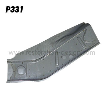
I got mine from Restoration Design (right side only) and was happy with the part: http://www.restoration-design.com/store/product/PP331
QUOTE(bbrock @ Jan 1 2020, 12:48 PM)
I got mine from Restoration Design (right side only) and was happy with the part: http://www.restoration-design.com/store/product/PP331
@bbrock .
Did it extend up higher to full height or was it just this lower portion only? I originally looked at RD but thought this was only the lower. From @bkrantz post, I think he is looking for the upper portion only.
QUOTE(Superhawk996 @ Jan 1 2020, 10:57 AM)
QUOTE(bbrock @ Jan 1 2020, 12:48 PM)
I got mine from Restoration Design (right side only) and was happy with the part: http://www.restoration-design.com/store/product/PP331
@bbrock .
Did it extend up higher to full height or was it just this lower portion only? I originally looked at RD but thought this was only the lower. From @bkrantz post, I think he is looking for the upper portion only.
It is the lower only as seen in the pic. I did do a bit of patchwork in the upper section but the areas I had to do were easy to fabricate.
QUOTE(Superhawk996 @ Jan 1 2020, 10:57 AM)
QUOTE(bbrock @ Jan 1 2020, 12:48 PM)
I got mine from Restoration Design (right side only) and was happy with the part: http://www.restoration-design.com/store/product/PP331
@bbrock .
Did it extend up higher to full height or was it just this lower portion only? I originally looked at RD but thought this was only the lower. From @bkrantz post, I think he is looking for the upper portion only.
Yes, I need only the upper section, with all the compound curve shapes.
OK Oscar, you have put my work to shame....
What you are doing is so far out there for a DIY in the garage venture!
Hats off to you -

What you are doing is so far out there for a DIY in the garage venture!
Hats off to you -
Lots of work the last 3 weekends in the aptly named Hell Hole.
1st week was prepping the part of the rear longitudinal that attaches to the wheelhouse inner.
I nearly forgot to put on the two weld studs that secure the trunk torsion springs.
Click to view attachment
Then there was the obligatory hole drilling for the puddle welds and then painted the inside of the C-section with Eastwood frame coating but masked the weld flanges to keep them clean.
Click to view attachment
This Eastwood coating really seems to take the heat well and doesn't flake off after the heat of welding in the vicinity but at the same time I'm going really slow and making sure the overall sheet metal outside the immediate weld area doesn't heat up beyond what I can touch with a bare hand. This makes for really slow welding.
Of course there was a lot of time spent tweaking fits and getting the frame angle to match the driver side.
Click to view attachment
Click to view attachment
The attachement to the rear of the engine compartment and the front of the rear shock tower is a special kind of hell. 1st the area had to be cut open which of course was done long ago. But even so I ended up not quite gettting the top frame tab where I would have liked. I couldn't close up the air gap between the tab and the shock tower. Trying to do the puddle welds would have just resulted in buring out the flange and/or a giant booger weld. Ultimately I decided to live with this and do a couple little stitches where I had solid metal to metal contact since that little top tab really isn't carrying much load. The side flange and the bottom flange will take most of the load.
Click to view attachment
To top all that off, there is very little room inside this box section to manipulate the torch.
When it was all done, I dusted the tuna can flap with some Eastwood in anticipation of being able to put that flap back in postion either this week after work or early in the weekend.
Click to view attachment
Lots of out of position welding on this section and the need to weld slowly, and constantly monitor the outer rear trailing arm pick up points for movment made this a slow painful ordeal. When it was all said and done, the suspension points hadn't moved so I'm going to call this past couple of weeks a success.
1st week was prepping the part of the rear longitudinal that attaches to the wheelhouse inner.
I nearly forgot to put on the two weld studs that secure the trunk torsion springs.
Click to view attachment
Then there was the obligatory hole drilling for the puddle welds and then painted the inside of the C-section with Eastwood frame coating but masked the weld flanges to keep them clean.
Click to view attachment
This Eastwood coating really seems to take the heat well and doesn't flake off after the heat of welding in the vicinity but at the same time I'm going really slow and making sure the overall sheet metal outside the immediate weld area doesn't heat up beyond what I can touch with a bare hand. This makes for really slow welding.
Of course there was a lot of time spent tweaking fits and getting the frame angle to match the driver side.
Click to view attachment
Click to view attachment
The attachement to the rear of the engine compartment and the front of the rear shock tower is a special kind of hell. 1st the area had to be cut open which of course was done long ago. But even so I ended up not quite gettting the top frame tab where I would have liked. I couldn't close up the air gap between the tab and the shock tower. Trying to do the puddle welds would have just resulted in buring out the flange and/or a giant booger weld. Ultimately I decided to live with this and do a couple little stitches where I had solid metal to metal contact since that little top tab really isn't carrying much load. The side flange and the bottom flange will take most of the load.
Click to view attachment
To top all that off, there is very little room inside this box section to manipulate the torch.
When it was all done, I dusted the tuna can flap with some Eastwood in anticipation of being able to put that flap back in postion either this week after work or early in the weekend.
Click to view attachment
Lots of out of position welding on this section and the need to weld slowly, and constantly monitor the outer rear trailing arm pick up points for movment made this a slow painful ordeal.
When it was all said and done, the suspension points hadn't moved so I'm going to call this past couple of weeks a success.
Nice work. Don't take this the wrong way, but it's nice to see someone of your skill complaining about all those awkward places where there is no room to manipulate the torch. Gawd those were frustrating.
This is a "lo-fi" version of our main content. To view the full version with more information, formatting and images, please click here.