tygaboy
Aug 11 2022, 04:43 PM
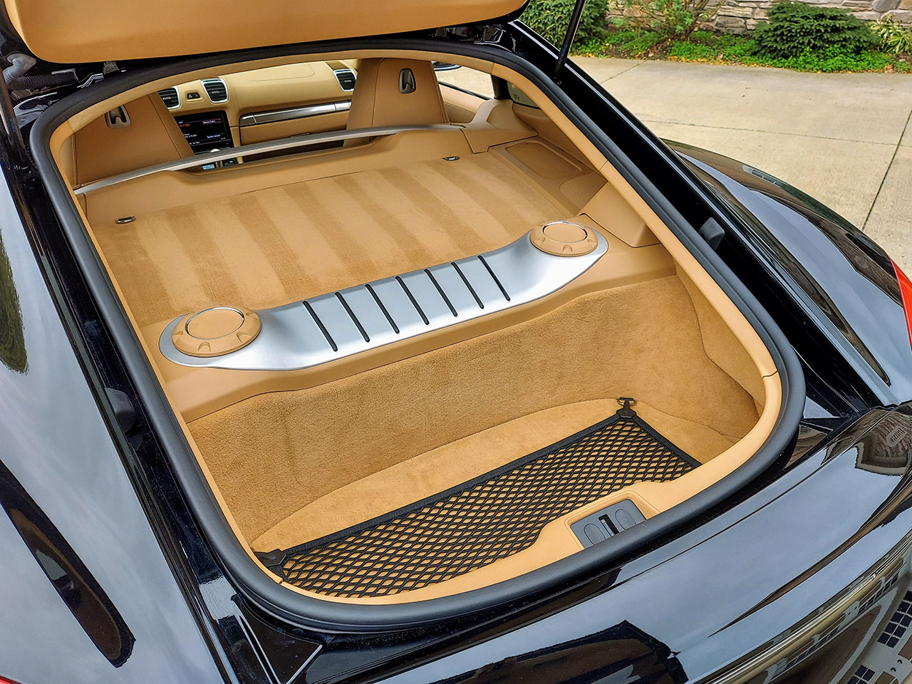
And finally, a super rough idea of the abbreviated trunk - and yes, it'll seal against the underside of the trunk lid! It'll probably be a bit smaller than what's implied here, and clearly needs a bunch of fab, but you get the idea.
I'm digging this, big time!

Cairo94507
Aug 11 2022, 05:13 PM
@tygaboy - Hey Chris, Nice progress. And, a mini-trunk is better than no trunk. I think that is going to look cool.
SirAndy
Aug 11 2022, 05:29 PM
QUOTE(tygaboy @ Aug 11 2022, 03:43 PM)

And finally, a super rough idea of the abbreviated trunk - and yes, it'll seal against the underside of the trunk lid! It'll probably be a bit smaller than what's implied here, and clearly needs a bunch of fab, but you get the idea.
Are you going to cut the top down to fit? That would be awesome!

tygaboy
Aug 11 2022, 05:33 PM
QUOTE(SirAndy @ Aug 11 2022, 04:29 PM)
QUOTE(tygaboy @ Aug 11 2022, 03:43 PM)
And finally, a super rough idea of the abbreviated trunk - and yes, it'll seal against the underside of the trunk lid! It'll probably be a bit smaller than what's implied here, and clearly needs a bunch of fab, but you get the idea.
Are you going to cut the top down to fit? That would be awesome!
- Better than that is I'm noodling on modifying an early 911 targa top - the ones that fold up - to work on this car. It would fit in this trunk! No promises but...
jb_11
Aug 12 2022, 06:46 AM
tygaboy, I followed you here from the RacerBenz thread at GRM and have been watching your builds with admiration for awhile. Amazing work. Thanks for sharing so many details (good and bad). It's great to see the process.
That mini trunk mockup really reminds me of a Cayman rear trunk.
markhoward
Aug 12 2022, 07:05 AM
Love the trunk Chris. Can’t wait to put my eyes on the car.
eric9144
Aug 12 2022, 09:28 AM
tygaboy
Aug 12 2022, 10:56 AM
F-NARP build, Day 2.
Let's start with the obvious: No, I likely won't keep up this pace. I'm just so excited to be back to fabrication and noodling on design and "engineering"

But I was back at it bright and early this morning and rough cut the rear of the trunk so I could get the drive train to final height. Here's where we ended up at the back.
I didn't fully remove that floor piece as I was thinking I may be able to bend it and retain the factory seam where it attaches the the rear panel. It'll need cutting at some point but I want to do as little re-work as possible.
tygaboy
Aug 12 2022, 10:59 AM
There's now clearance at the cam belts but I don't have the covers on there so it's likely thing will have to move rearward a bit.
tygaboy
Aug 12 2022, 11:01 AM
Here's the important part: the bottom of the drive train is higher than the bottom of the chassis. Maybe hard to tell from this pic but it's higher.

And just LOOK at that COLOR! It's so cool...
Also, before you get too excited, those /6 mounts will have to come out. The driver's side colides with the alternator and it just doesn't make sense to try and use them "just because they're already there".
tygaboy
Aug 12 2022, 11:05 AM
Quick poll: Yikes! or Oh, YEAH!
Just look where that plenum is going to be!
I'm voting "Oh, Yeah!
I have an old engine lid I'm going to cut it so we'll know exactly what this thing will look like.
tygaboy
Aug 12 2022, 11:07 AM
And before you get all excited and think you've done all the needed clearancing...
As Max said: "Missed it by THAT much!"
SirAndy
Aug 12 2022, 11:18 AM
What's the angle on the drive shafts? I'd rather reshape the firewall a bit to make the front covers fit than moving everything even further back.
The less angle on a drive shaft, the better.

PS:
tygaboy
Aug 12 2022, 11:42 AM
QUOTE(SirAndy @ Aug 12 2022, 10:18 AM)
What's the angle on the drive shafts? I'd rather reshape the firewall a bit to make the front covers fit than moving everything even further back.
The less angle on a drive shaft, the better.
PS:
The angle is WAY better than on my LS car. Nothing is finalized and forward is better for fitment of that trans mount, too. Still work to do, for sure.
sportlicherFahrer
Aug 12 2022, 12:38 PM
Cut engine lid would look pretty rad. That idea gives me another. Have you settled on a name for the project? If not, might I suggest Roter Kopf as an homage to another car sharing similar attributes? I think it translates right, but
@SirAndy may have a better translation on that one.
Looking forward to seeing this build at the next WCR!

tygaboy
Aug 12 2022, 01:09 PM
Thanks to Robert
@buddyv , I had this spare engine lid. A bit of measuring and cutting and...
BAM! There it is! Not even going to obstruct rearward vision! As expected, the trunk is going to need some surgery but that'll wait until the rest of the intake is worked out.
But holy jeebus, this thing is going to be so cool.

If you voted "Yikes" earlier, well, I'm sorry. You're wrong!


Jett
Aug 12 2022, 02:10 PM
QUOTE(tygaboy @ Aug 12 2022, 12:09 PM)
Thanks to Robert
@buddyv , I had this spare engine lid. A bit of measuring and cutting and...
BAM! There it is! Not even going to obstruct rearward vision! As expected, the trunk is going to need some surgery but that'll wait until the rest of the intake is worked out.
But holy jeebus, this thing is going to be so cool.
If you voted "Yikes" earlier, well, I'm sorry. You're wrong!
Amazing!!
Now you need an acrylic cover like the F cars have.
autopro
Aug 12 2022, 02:33 PM
Oh God that is going to look good with the engine peaking out like that

ssuperflyoldguy
Aug 12 2022, 05:14 PM
You are KILLING me... And prob a few others
Front yard mechanic
Aug 12 2022, 05:48 PM
Enzoenvy
worn
Aug 12 2022, 06:17 PM
QUOTE(tygaboy @ Aug 12 2022, 12:09 PM)
Thanks to Robert
@buddyv , I had this spare engine lid. A bit of measuring and cutting and...
BAM! There it is! Not even going to obstruct rearward vision! As expected, the trunk is going to need some surgery but that'll wait until the rest of the intake is worked out.
But holy jeebus, this thing is going to be so cool.
If you voted "Yikes" earlier, well, I'm sorry. You're wrong!
You know that cutting the lid doesn’t exactly solve the problem. In the same way that you cannot quite look past that cool supercharger up front in the hot rods. Which you need to add. Couldn’t be in better hands. Rock on.
DTMLGND
Aug 13 2022, 08:51 AM
Subcribed!!
![popcorn[1].gif](http://www.914world.com/bbs2/style_emoticons/default/popcorn[1].gif)
This is very cool.
Krieger
Aug 13 2022, 10:13 AM
horizontally-opposed
Aug 14 2022, 12:12 PM
Gotta say…as much as I loved the idea of lowering the plenum to make this a sleeper, this is gonna look great—and people are going to
trip out.
"Yeah but the engine in those—hey, waitaminute…what?!"
I've been a longtime fan of engine swaps, but this one may just take the cake...
Chris914n6
Aug 14 2022, 01:36 PM
At this point I think I would seriously consider making the trunk lid shorter and engine lid longer.
For the inlets I'd make a slip fit down turn instead of cutting/welding the intake. It's going to be visible so make it pretty.
I'd also keep the factory oil/water cooler. They chose to do it that way for a reason plus it works fine.
horizontally-opposed
Aug 14 2022, 02:00 PM
^^ Interesting points.
But engine lid longer, with its seam moved further back, will violate a key 914 graphic established by the ends of its targa bar—as will, of course, a Ferrari engine…though that kinda gets a pass.
I wonder about some of Porsche's early attempts to make a single-piece, rear-engined decklid and engine cover for the 914…something Chris is certainly aware of. Then it's "just" one hole in the middle-
ish for that red intake plenum. Just thinking out loud…
Fully agree on making the turndown(s) pretty, but have no worries with Chris at work...
roundtwo
Aug 14 2022, 02:31 PM
.....and here were go again! ...

tygaboy
Aug 14 2022, 07:47 PM
Not much progress this weekend as Saturday was dedicated to finishing up the intercooler install on the Lotus 7 replica. Then this morning,
@Krieger Andy came by to drive my 914 and give me some advice on alignment / spring rates, as well as some input on this build.
In the afternoon,
@Retroracer Tony stopped by on his way from Bend to the South Bay. We geeked out on the Ferrari build and he gave me his usual excellent input on a few things. Then we took the E9 for a short drive to grab lunch. Best of all, he presented me with the COOLEST gift! I need to take some time and get pics before I post about it but let me just say, it's one of the neatest things I've ever received. I hope when you see it, you'll agree.
Anyway, once the always important social stuff wrapped up, I was able to do a rough cut of removing the engine tray tin and the /6 mounts - and remember, those mounts interferred with things like the alternator so they simply weren't going to work. Removal of all this allows me to get a complete understanding of the room I have for things like exhaust and what I'm thinking will be a cradle-style engine/trans mount. Just a bit more clearancing and I'll be able to start in on fabbing the mounts!
Spoke
Aug 14 2022, 09:43 PM
That induction system peeking out of the bodywork reminds me of the 917.
Krieger
Aug 14 2022, 10:58 PM
Chris, your car is blazing fast and drives very nicely! Thank you for sharing that driving experience with me! Your work is impressive!
tygaboy
Aug 15 2022, 09:12 AM
@Chris914n6 - I was toying with the idea of making a short "trunk lid" that was sized to work with the abbreviated trunk. But as
@horizontally-opposed Pete points out, I'd end up with a body line in a location unrealted to any other design queues - so that's off the table. So, what to do?
@Retroracer Tony to the rescue! Let me first say that if it weren't for Tony and his "quick sketches" (which are auto art, IMO!), I likely wouldn't have hood vents on my LS build. Or, if I did, they'd certainly be less cool! So, to be clear, I regularly consulted with him on styling ideas for my LS build and he was always willing to listen to my silly "I wonder if..." then noodle up a few ideas - most of which I just love! And this build is no different:
I've been talking with Tony and texting him various pics for the past few weeks. When he stopped by yesterday, he gave me this (among other drawings that I'll share later) as one of a few ideas for the engine cover/trunk. It's a leading contender at this point.
Yes, minor shape and dimension changes will be needed to work in the real world, just like with his hood vents, but it's the inspiration that's most important to me. Well, that and knowing there are other folks out there that want to see this project come togther in the best possible way.
Tony - Thank you, my friend! I couldn't do this without you. Literally. It's so great to get your fingerprints on this build, too.


Superhawk996
Aug 15 2022, 09:21 AM
YES!
KELTY360
Aug 15 2022, 09:59 AM
OMG!! How perfect is that?!!
![shocked[1].gif](http://www.914world.com/bbs2/style_emoticons/default/shocked[1].gif)
tygaboy
Aug 15 2022, 06:03 PM
Back to the mundane stuff like getting the drive train mounted.
In a blast from the past, I spent a couple hours on the phone with my fab buddy Martin to get another set of eyeballs on the design I worked up for the cradle. If it's not already clear, I fully expect any number of folks to have significant input on this build. I have no ego around asking for/paying for help. Especially if it means the outcome is what I want it to be.
But back to Martin: As expected, he had a number of great suggestions, both structurally and design-wise. Best is that, overall, we agreed the cradle approach is a solid base design. Yea!
And for those interested, the pic shows the water-to-oil heat exchanger that helps initially heat and then stabalize the trans fluid temps. The arrows are pointing at the connections for the factory, belt-driven water pump which lives at the front of the valley. You can also see how they decided to get the water into the block near each cylinder via that "spider" looking H2O distribution component (external vs the GM internal circulation approach...) as well as the braided lines that get the oil in/out to the trans. The trans fluid pump is inside the trans.
So there's today's "how Ferrari decided to do it" lesson! Be preparred for a quiz tomorrow!
Still tbd if I'm going to run the factory water pump or go with an electric pump and just route to the in/out locations you see here.
Just a few days into this and I can confidently state: This is WAY more complicated than just stuffing things into the chassis, because Ferrari. But hey, if it were easy, everyone would be doing it.
tygaboy
Aug 15 2022, 07:09 PM
Seems everyone on my contributing team likes to sketch! Here's Martin's cut at one side of the cradle we noodled up. The tabbed bracket on the right if the sketch welds to the lower firewall, the "j" shape tube is one side of the cradle, the bracket on it is where the Ferrari engine mount sits and the part with the "?" and arrow is the rear mounting bracket that'll weld on between the 914 factory trans mount/cross bar and the round tube cross bar you saw in the earlier pics.
Then once the headers are sorted (which is a "whole 'nother" packaging challenge), I'd like to see a bar that ties from the long, just ahead of the suspension console, down to the J tube at/near the engine mounting pad.
Coming along and nearly to the point where it's time to start fabbing all this. Exciting times!
bkrantz
Aug 15 2022, 08:55 PM
You know, if you really want to give old man Enzo (and old man Ferdinand and just about everyone else) a heart attack, you could turn the drive train around, and make a rear-engine VW-Porarri.
Krieger
Aug 15 2022, 10:46 PM
WOW! Tony's sketches of the humps are a perfectly natural addition!
Cairo94507
Aug 16 2022, 06:23 AM
I agree with Andy, love Tony's sketch and that he is matching the "humps" to the front fenders. Looks great.
tygaboy
Aug 17 2022, 08:59 AM
Design refinement. After more chassis clearancing and getting the drive train in what I'm pretty sure is final location, I bolted on the alternator. Good thing because is sits right where I was thinking a front engine mount could go. Not that I was close to welding anything, but... Sort of a "pants first, then shoes" moment. But you know me: You're going to get full transparency as I make my way through this.
tygaboy
Aug 17 2022, 09:06 AM
I passed this new info and the pics along to Martin, we kicked around a couple ideas and he sent a sketch of the latest thinking. Note it's not to scale, just "to concept". The plan is 3" x 1" .095 wall for those main tubes, even though the sketch makes them look far larger.
It's just not possible to get a cross bar to sit directly under the engine mounts so the one you see fits in a raised section just ahead of the trans, a bit behind the mounts.
And yes, this drawing it's missing the rear section. Which is OK as it's far more straight forward than working out these main engine mounts.
Today's IRL exercise will be to get some tubes mocked into position and work out more accurate dimensions.
Hey, it's a process. And this is the part I just LOVE. Driving them is fine, I like makin' stuff!


ClayPerrine
Aug 17 2022, 03:26 PM
QUOTE(tygaboy @ Aug 17 2022, 10:06 AM)

I am exactly the same. I can't leave well enough alone. I even have plans on how to put a full Cayman rear suspension under a 914 chassis........
We definitely need a bad idea smiley.
Clay
tygaboy
Aug 20 2022, 09:26 AM
When you don't have a 3d scanner, skills with Fusion 360 (or the like) or even a lift:
1. stand there looking at the drive train in the chassis
2. imagine how some design might work
3. try and keep track of things that aren't there - shift cables, water lines, wiring, exhaust system...

4. crawl around / scoot around / reach around
trying to measure
5. mock up ideas with scrap and other random parts
6. take pics
7. get on the phone with Martin, email pics and noodle on the latest info
8. wait a bit for Martin to email his latest drawing
9. Repeat steps 2 through 8
Slower than it might otherwise be, but we're making progress. These latest designs account for the engine cradle and the rear transmission mounting system (TMS) - it will live between the rear suspension towers - but they're missing the mount where the engine cradle's vertical elements tie to the TMS. I've sent a rough drawing to Martin with an idea I like and expect later today he'll send an updated set of drawings. Almost ready to cut parts!
As I mentioned earlier, mounting this drive train is turning out to be a bit more complicated than I expected. I suspect this will be a recurring theme on this build.
tygaboy
Aug 20 2022, 12:15 PM
My, how quickly plans can change. Another round of planning w/Martin this morning and...
To optimize the Ferrari trans hanger mount, and with all the other stuff planned for this build, it started making more sense to lose the factory trunk and trans cross bar. So out it comes.
tygaboy
Aug 20 2022, 12:18 PM
And a better, no-twisting-moment, trans mount system can be installed. Just mocked in approximate location, as you can see, but the transmission mounting tab will sit between these bars. Structurally better, for sure.
I'll fab a removable trunk floor/wall that can seal against the trunk lid but be taken out to show off all the mechanicalness.
tygaboy
Aug 20 2022, 12:21 PM
And the updated, not-to-scale sketch of the trans mount with the bracket to connect the engine cradle vertical. One of those tabs on each side of the vertical.
tygaboy
Aug 20 2022, 12:25 PM
And I hope you enjoy seeing this level of development process vs me just posting when something is actually complete. I like to document for posterity's sake.
davep
Aug 20 2022, 02:16 PM
You bet, this is an Epic build!
Montreal914
Aug 20 2022, 07:18 PM
Although I can see the performance benefits, I am not into conversions with with non-P power train.
BUT, this one is clearly something else!

Please continue to share all of the development and these wonderful period correct work of art hand made sketches
. I grew up learning mechanical engineering from my dad (mechanical draftsman and all around craft person) and always admired his hand sketch skills. No modern CAD can transmit the artistic aspect of engineering like those hand sketches.
You and Martin make a wonderful duo. This will be a nicely engineered and well built car!
tazz9924
Aug 20 2022, 09:22 PM
QUOTE(tygaboy @ Aug 20 2022, 07:26 AM)
When you don't have a 3d scanner, skills with Fusion 360 (or the like) or even a lift:
1. stand there looking at the drive train in the chassis
2. imagine how some design might work
3. try and keep track of things that aren't there - shift cables, water lines, wiring, exhaust system...
4. crawl around / scoot around / reach around
trying to measure
5. mock up ideas with scrap and other random parts
6. take pics
7. get on the phone with Martin, email pics and noodle on the latest info
8. wait a bit for Martin to email his latest drawing
9. Repeat steps 2 through 8
Slower than it might otherwise be, but we're making progress. These latest designs account for the engine cradle and the rear transmission mounting system (TMS) - it will live between the rear suspension towers - but they're missing the mount where the engine cradle's vertical elements tie to the TMS. I've sent a rough drawing to Martin with an idea I like and expect later today he'll send an updated set of drawings. Almost ready to cut parts!
As I mentioned earlier, mounting this drive train is turning out to be a bit more complicated than I expected. I suspect this will be a recurring theme on this build.
My process is very similar except when step 7 comes around, instead of getting on the phone i get on the computer and want to punch it sometimes. Then realize i messed it up hopefully before waiting a week for laser cut parts to arrive and repeat.
nathanxnathan
Aug 21 2022, 12:30 PM
I love the drawings — speaking my language
This is a "lo-fi" version of our main content. To view the full version with more information, formatting and images, please
click here.