tygaboy
Aug 21 2022, 04:45 PM
Well, sorry to report there will be no more drawings as I've decided to cancel this project.
This piece of crap chassis is rusty and I just don't think I can deal with it...

Interesting though and another example of "Every 914 has rust. You just haven't found it yet..." No sign of failure anywhere along the seam sealer but mositure found its way in. Granted, it's right behind the rear tire so I'm sure this area got hammered from underneath, but anyway, there you go.
tygaboy
Aug 21 2022, 04:52 PM
The rust discovery was part of removing aaaaaaallllll the remnants of the factory trans mount cross bar and trunk floor panel. Messy, messy work. I need to get all this out of the way so I can weld in the spreader plates that will support the Ferrari trans mount cross bars.
You can see the approach was to remove all the unneeded material. That "hole" is where the factory trans mount cross bar used to attach.
With the removal complete, I reshaped the open area to accept the spreader plate.
tygaboy
Aug 21 2022, 04:59 PM
Then it's the typical fab process:


- make a cardboard template of the needed shape
- transfer it to metal
- cut, fit, trim, fit
- bend to match the curve of the area to which it'll be welded
- fit, trim, bend, rebend, un-bend, fit...
You get the picture.
You can see how the spreader plate will weld to the inside wall of that opening then turn 90 degrees and get welded to the outer wall of the box section.
tygaboy
Aug 21 2022, 05:08 PM
I'm really happy with the fit I was able to get. And with that done, I drilled for the plug welds. With those complete, the part is clamped in place. A quick check of each hole shows that the spreader plate sits flush against the inner panel, just like it should.
Note that there will be another spreader plate that covers this one and extends to support the upper cross bar. It'll make sense once I get to that piece.
tygaboy
Aug 22 2022, 05:09 PM
More messy work grinding all those factory spot welds and removing sheetmetal to prep the passenger side for the lower cross bar's inner spreader plate. But it's all set to go. I got a nice fit here, as well. Tommorrow I'd like to get these welded in and maybe even get the outer spreader plates fab'd, too.
Probably one more messy session and I'll have all the unneeded sheet metal removed from engine bay/trunk area.
mgarrison
Aug 23 2022, 01:15 PM
Such outstanding, uber cool fab work as usual Chris!

Cairo94507
Aug 23 2022, 01:24 PM
A master fabricator for sure.

tygaboy
Aug 23 2022, 02:41 PM
Prep'ing the inner spreader plates includes coating the surfaces with weld through primer.
Your PSA for today:
Don't weld directly on weld through primer - never weld anything but clean metal.
Weld through primer is designed to liquify and galvanize the metal around the weld to help protect from future corrosion. It helps provide permanent rust protection on the inner edges of the welded metal pieces.
So, prep the area by spraying on the primer (the stuff I used happens to be black in color) then remove it completely from the area where you'll be welding. I just positioned the spreader plate and scratched where the plug welds would be then came back with a cheap-o Harbor Freight 3/8 belt sander and cleaned each weld location.
tygaboy
Aug 23 2022, 02:43 PM
Plug welded! I use MIG for this as it's faster and easier, at least for me. I get what I think is a really nice result without having to worry about getting all comfortable, like I would need to do if TIGing.
I'll come back and edge weld in a few locations, just to lock the plate in a bit more.
tygaboy
Aug 23 2022, 02:46 PM
Next was to final trim the 90 degree return and weld that edge from top to bottom.
A bit of sanding to smooth out all the areas where the outer spreader plate will sit then hit the whole area with weld through primer.
Ready for the outer plate fab and installation.
tygaboy
Aug 23 2022, 03:03 PM
@mgarrison @Cairo94507 - Thanks for the kind words, gentlemen.
I will say that this build has me really pushing to do the best I possibly can, not that I don't do that all the time, just that this car feels like it could turn out to be something really special.
tygaboy
Aug 24 2022, 02:31 PM
Today, I grabbed the factory 360 trans mount. This is quite a piece! It's WAY lighter than it looks and a quick rough fit suggests it could be adapted to work in the 914 - but it's quite bulky looking and hides a lot of the cool-factor. Maybe it can be sliced up and that rear hanger section could be used?
The good news is that if this gets used or not, the plating I've done is still required so no lost effort... so far.

Anyway, multiple options are always good. Much more to do before final decisions are made.
ClayPerrine
Aug 24 2022, 02:39 PM
QUOTE(tygaboy @ Aug 24 2022, 03:31 PM)

Today, I grabbed the factory 360 trans mount. This is quite a piece! It's WAY lighter than it looks and a quick rough fit suggests it could be adapted to work in the 914 - but it's quite bulky looking and hides a lot of the cool-factor. Maybe it can be sliced up and that rear hanger section could be used?
The good news is that if this gets used or not, the plating I've done is still required so no lost effort... so far.
Anyway, multiple options are always good. Much more to do before final decisions are made.
Suggestion... use the rear portion of the factory 360 trans mount in the back. Then take the remains of the mount after you cut the trans crossbar off of it, and put it under the engine to support the motor mounts. Then add risers on the rear to reconnect it it to the trans crossbar. Make it bolt to the trans crossbar so you can remove it to get the engine out of the car.
My mental 3d modeling says it should work. But I am not there to examine it in person.
Clay
tygaboy
Aug 24 2022, 05:47 PM
QUOTE(ClayPerrine @ Aug 24 2022, 01:39 PM)
Suggestion... use the rear portion of the factory 360 trans mount in the back. Then take the remains of the mount after you cut the trans crossbar off of it, and put it under the engine to support the motor mounts. Then add risers on the rear to reconnect it it to the trans crossbar. Make it bolt to the trans crossbar so you can remove it to get the engine out of the car.
My mental 3d modeling says it should work. But I am not there to examine it in person.
Clay
@ClayPerrine - Clay - After playing around with that mount (note that it's aluminum), it's just too much not the look I want. Your suggestion about reusing part of it? The wall thickness is way too thin for a support structure.
When you put this piece in context with the rest of the 360 chassis, it's pretty clear it's about tying together the right/left sides of the rear section of the Ferrari and providing places to mount a few light weight items. A case of "close, but no cigar".
I went to the metal store today and stocked up on 1" x 3" x .095 wall tube. Martin and I worked up some changes to the last design that adds an outrigger from the cradle to the long, just ahead of the suspension console.
Give me a few days and I hope to have V1 of the cradle underway.
steuspeed
Aug 25 2022, 01:13 AM
QUOTE

100%.
(Another massive Rush nerd.....

)
Clay
Couple walks by by place last summer. Takes a look at my collection. 2 914s, Alfa Alfetta, Scirocco Mk1. Working Man playing out the garage. He says, all these cars are turning into Red Barchettas. I say, Yes.... yes they are.
steuspeed
Aug 25 2022, 01:44 AM
I would go with the Raspberry, but with those red valve covers it needs to be silver or gunmetal imo. Something like that to show it off. I would be looking at paint chips next to the covers. Porsche Marathon Blue Metallic might be an option?
Ferrari Grigio Ferro
https://rossoautomobili.com/blogs/magazine/...-ferrari-silverTrunk mods, excellent!
POORARI love it!
tygaboy
Aug 25 2022, 01:05 PM
Before plating for the upper cross bar, I have to get that whole area to be in the same plane so the spreader plate has no gaps behind it.
A quick trim of some 18 ga and I have that piece ready to weld in.
tygaboy
Aug 25 2022, 01:06 PM
First rough fit of the 12 ga upper spreader plate. Still some trimming / fitting to do but you get the idea.
ClayPerrine
Aug 26 2022, 06:16 AM
Just a suggestion...
Get Ferrari Modena brakes for it. They are Brembo monoblocks, the exact same as the Boxster brakes, but they have Ferrari on the face of them. So you don't have to engineer anything, just bolt them on. Put them behind Fuchs with the Porsche crest in the center.
That would mess with both the Porsche and Ferrari purists big time.

Clay
tygaboy
Aug 26 2022, 09:17 AM
QUOTE(ClayPerrine @ Aug 26 2022, 05:16 AM)
Just a suggestion...
Get Ferrari Modena brakes for it. They are Brembo monoblocks, the exact same as the Boxster brakes, but they have Ferrari on the face of them. So you don't have to engineer anything, just bolt them on. Put them behind Fuchs with the Porsche crest in the center.
That would mess with both the Porsche and Ferrari purists big time.
Clay
Clay, Well timed, sir! The conversation and initial decison about caliper labeling happened yesterday afternoon! And what is that decision?
Well, you'll just have to stay tuned to hear about it and a couple of other big changes in direction...
tygaboy
Aug 26 2022, 09:32 AM
Messy, boring, necessary prep for the outer spreader plate.
ClayPerrine
Aug 26 2022, 11:54 AM
QUOTE(tygaboy @ Aug 26 2022, 10:17 AM)
QUOTE(ClayPerrine @ Aug 26 2022, 05:16 AM)
Just a suggestion...
Get Ferrari Modena brakes for it. They are Brembo monoblocks, the exact same as the Boxster brakes, but they have Ferrari on the face of them. So you don't have to engineer anything, just bolt them on. Put them behind Fuchs with the Porsche crest in the center.
That would mess with both the Porsche and Ferrari purists big time.
Clay
Clay, Well timed, sir! The conversation and initial decison about caliper labeling happened yesterday afternoon! And what is that decision?
Well, you'll just have to stay tuned to hear about it and a couple of other big changes in direction...
You have probably heard the old saying "Great minds run in the same channel." In our case, too bad it's the gutter.

Clay
tygaboy
Aug 26 2022, 05:34 PM
And there's the right side, outer spreader plate plug welded. It'll get some skip welds along its edges, too. I just haven't gotten to that.
And to appease the fabrication gods so they ensure nothing fails, at the completion of any particular area, it's always a good idea to say, out loud, "OK! That's not going anywhere!"
Note that all the plug welds will be sanded smooth and all edges will be seam sealed.
tygaboy
Aug 26 2022, 05:36 PM
Left side upper, inner plate plug welded, sanded, primed and ready for the outer spreader.
tygaboy
Aug 26 2022, 05:41 PM
Without going into the excrutiating details I'm working to understand, it's V4-ish of the rear transmission mount system, including some style points for the upper shock mount area. Just kicking ideas around...
tygaboy
Aug 27 2022, 06:02 PM
Left side upper spreader in place. I clamp near each hole as I'm plug welding it to be sure the plate is firmly contacting the parent material.
tygaboy
Aug 27 2022, 06:03 PM
Both upper spreaders are welded and sanded.
tygaboy
Aug 27 2022, 06:05 PM
Now to determine the location for the upper trans mount cross bar.
I thought my LS set up was cool, but this thing...man.

tygaboy
Aug 28 2022, 11:25 AM
Engine mounting fun:
The tricky part is that the Ferrari has a chassis that's shaped to support the engine mounts - these supports are a fixed part of the chassis. And becaure the engine is wider at the top than the mount width, the drive train has to come out the top of the car. That's not something I want to have to do, if I can at all help it.
So I have to come up with an intermediate "something" that's removeable and allows the engine to be lowered out the bottom.
Much noodling and head scratching has yeilded this design for what I've taken to call the "landing pads". Essentially, it's a permanent addition to the 914 chassis that's as wide as it can be while still allowing the engine to clear. Then we have a removable chunk of a mount that connects to this structure and serves as the landing pad.
This structure isn't quite final as that tube that heads outward is only a place-holder and will need to angle up to the long. There will also be gusseting from this up to as high as practical on the chassis / cage tubing to combat any twisting force.
Today's goal is to cut a few of these pieces and mock this up in the chassis.
Note that this current design eliminates any tubing from the motor mount rearward: no more cradle approach. This eliminates any potential interference or "no-go" zones for things like the axles, exhaust or, in the case of the right side, the shifter cables.
Van B
Aug 28 2022, 01:14 PM
Random suggestion: you should count all the times you had to put the powertrain in place for mock ups. I’ve often wondered how many times should be expected for a custom build… probably close to 100 or more by the time it’s all done!
tygaboy
Aug 28 2022, 02:17 PM
QUOTE(Van B @ Aug 28 2022, 12:14 PM)
Random suggestion: you should count all the times you had to put the powertrain in place for mock ups. I’ve often wondered how many times should be expected for a custom build… probably close to 100 or more by the time it’s all done!
That's the sort of thing, along with adding up receipts, that I really do not want to do!

But to date, I'm probably approaching ten to get to this point. Fortunately, Most of what's been going on requires the drive train be in place.
One of the ideas I had was to make a fixture that duplicates the motor mount locations and the trans mount tab. It'd be made such that when it was leveled front/back and side/side in the leveled chassis, all I'd have to know is the distance from the fire wall to the motor mount location and I could build all the mounts to the fixture.
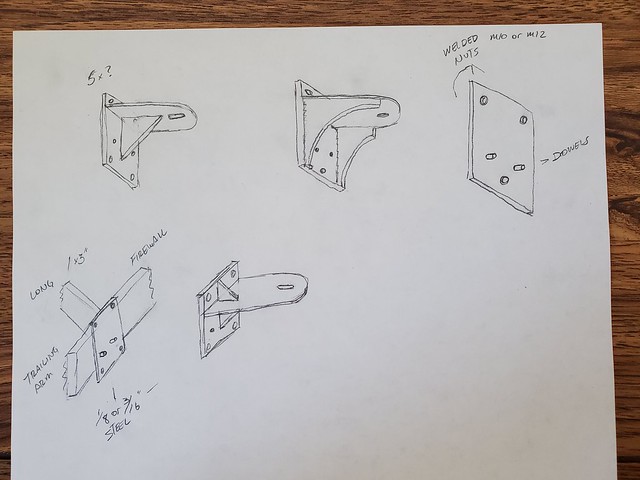
Chris914n6
Aug 28 2022, 03:44 PM
I simplified it. Loosen the motor mount bolt, remove 4 bolts, repeat, drop. Weld the nuts to the chassis mount to make it easier. Pretty much standard formula for cars with multiple engine options. Tough part is the chassis mount as that area is not the strongest or best shaped part of the car. The trailing arm branch might need to be repurposed round tube. If you are concerned about bolt sheer add a dowel pin or two, plus they work great as locating pins.
QUOTE(Van B @ Aug 28 2022, 12:14 PM)
Random suggestion: you should count all the times you had to put the powertrain in place for mock ups. I’ve often wondered how many times should be expected for a custom build… probably close to 100 or more by the time it’s all done!
I only did it a handful of times. Once the trunk was trimmed and the motor was is in it's final place I cut and welded the crossbar together in car. Helps that I kept the 914 trans and had room under the motor for a typical crossbar. I had the trans bolted in and a crossbar on top of the car with the motor suspended by straps -- plenty of room under to move around.
HTH
Van B
Aug 28 2022, 05:35 PM
QUOTE(tygaboy @ Aug 28 2022, 04:17 PM)
QUOTE(Van B @ Aug 28 2022, 12:14 PM)
Random suggestion: you should count all the times you had to put the powertrain in place for mock ups. I’ve often wondered how many times should be expected for a custom build… probably close to 100 or more by the time it’s all done!
That's the sort of thing, along with adding up receipts, that I really do not want to do!
But to date, I'm probably approaching ten to get to this point. Fortunately, Most of what's been going on requires the drive train be in place.
One of the ideas I had was to make a fixture that duplicates the motor mount locations and the trans mount tab. It'd be made such that when it was leveled front/back and side/side in the leveled chassis, all I'd have to know is the distance from the fire wall to the motor mount location and I could build all the mounts to the fixture.
Oh man, I don’t EVER add up receipts! I hear you there for sure
tygaboy
Aug 28 2022, 05:48 PM
Cut the lower spreader outline to shape, clamp it to the chassis at the front and start working it to get the needed curve.
tygaboy
Aug 28 2022, 05:49 PM
All shaped and curved and clamped in place to verify fit in all areas. It turned out nicely.
tygaboy
Aug 28 2022, 05:51 PM
All plug welded and ready for sanding. Repeat on the other side and add a bit of edge welding and I'll be ready to add the rear cross bars. Things are moving right along!

tygaboy
Aug 28 2022, 05:55 PM
QUOTE(Chris914n6 @ Aug 28 2022, 02:44 PM)
I simplified it. Loosen the motor mount bolt, remove 4 bolts, repeat, drop. Weld the nuts to the chassis mount to make it easier. Pretty much standard formula for cars with multiple engine options. Tough part is the chassis mount as that area is not the strongest or best shaped part of the car. The trailing arm branch might need to be repurposed round tube. If you are concerned about bolt sheer add a dowel pin or two, plus they work great as locating pins.
HTH
@Chris914n6 - Thanks for the input. It's certainly a process and yep, all the odd shapes make it a bit more complex. In the end, whatever the design ends up being, it'll be over built for safety's sake.
tygaboy
Sep 4 2022, 02:48 PM
Careful what you wish for. I thought it was a super duper thing that the Ferrari transmission output flanges were higher than the Boxster S. Turns out they are really high. Too high? I'm working on figuring out exactly this.
Here's a really rough mock up with the drive train at proper-ish height in the chassis and the trailing arm set to approximate ride height.
Because of the output flange height, the wheel-side CV will never be higher than the trans output CV; it's all droop, all the time.
What I need to work out is: Can a 930 CV (which has a max limit of 28 degrees) stay in range during operation? I'm pretty sure I'll have to add limit straps to stop things drooping too far when I jack the rear wheels off the ground.
It may also require lowering the drive train in the chassis and building a rub bar/skid plate. It wouldn't be any worse than doing a dropped floor, in terms of ground clearance.
So. Many. Items. To. Work. Out.
tygaboy
Sep 4 2022, 03:08 PM
On a simpler note, the left side, lower rear spreader plate has been completed.
I got a nice fit on this side, too. A bit of grinding and it'll be ready for the transmission mount cross bars!
tygaboy
Sep 4 2022, 04:16 PM
Transmission mount cross bar locating in process. I have a fair bit of leeway so much of it is down to aesthetics.
That last pic shows the mounting tab sits well under the plane of the top of the bars. Important because that's where the floor of the removable trunk will sit.
Maltese Falcon
Sep 4 2022, 09:07 PM
QUOTE(tygaboy @ Sep 4 2022, 01:48 PM)
Careful what you wish for. I thought it was a super duper thing that the Ferrari transmission output flanges were higher than the Boxster S. Turns out they are really high. Too high? I'm working on figuring out exactly this.
Here's a really rough mock up with the drive train at proper-ish height in the chassis and the trailing arm set to approximate ride height.
Because of the output flange height, the wheel-side CV will never be higher than the trans output CV; it's all droop, all the time.
What I need to work out is: Can a 930 CV (which has a max limit of 28 degrees) stay in range during operation? I'm pretty sure I'll have to add limit straps to stop things drooping too far when I jack the rear wheels off the ground.
It may also require lowering the drive train in the chassis and building a rub bar/skid plate. It wouldn't be any worse than doing a dropped floor, in terms of ground clearance.
So. Many. Items. To. Work. Out.
Leather limit straps were used in the 935s in the past in order to deal with the suspension droop being over the limit for the on-board air jacks to allow for tire changes. Modern days with the introduction of nitrogen filled + adjustable specs (JRZ, Moton, KW, etc.), the internal discs can be internally adjusted to customer specs for any dedicated droop limit.
These JRZs out of the box had major rear suspension droop. Cary from ERP suspension came by to measure the JRZ units, took over to their shop for mods and now perfect.
Click to view attachmentClick to view attachment
tygaboy
Sep 4 2022, 09:20 PM
QUOTE(Maltese Falcon @ Sep 4 2022, 08:07 PM)
QUOTE(tygaboy @ Sep 4 2022, 01:48 PM)
What I need to work out is: Can a 930 CV (which has a max limit of 28 degrees) stay in range during operation? I'm pretty sure I'll have to add limit straps to stop things drooping too far when I jack the rear wheels off the ground.
Leather limit straps were used in the 935s in the past in order to deal with the suspension droop being over the limit for the on-board air jacks to allow for tire changes. Modern days with the introduction of nitrogen filled + adjustable specs (JRZ, Moton, KW, etc.), the internal discs can be internally adjusted to customer specs for any dedicated droop limit.
These JRZs out of the box had major rear suspension droop. Cary from ERP suspension came by to measure the JRZ units, took over to their shop for mods and now perfect.
@Maltese Falcon - I may need to give you a call to talk details. Thanks for chiming in!
stownsen914
Sep 5 2022, 07:16 AM
I've used bolt-on limiting straps to limit droop, and also plastic disks inside the shocks like Maltese Falcon mentioned to limit droop on different racecars. Either will do the trick.
stownsen914
Sep 5 2022, 07:17 AM
QUOTE(stownsen914 @ Sep 5 2022, 09:16 AM)
I've used bolt-on limiting straps to limit droop, and also plastic disks inside the shocks like Maltese Falcon mentioned to limit droop on different racecars. Either will do the trick. As long as you leave 2-3 inches of droop below normal ride height, you're good.
tygaboy
Sep 5 2022, 12:02 PM
For the trans mount cross bars, it looks like it's back to a revised version of a previous design. Shocking, I know. But there is a bit of a surprise / some style points when you see the overall design.
I also started in on the motor mounts. Many pieces yet to be fabbed but it gets a key item into CAD and proven to fit.
Hopefully, the drive train will be mounted in a week or so.
Van B
Sep 5 2022, 03:57 PM
That poor mount… oh the abuse it will suffer lol
tygaboy
Sep 5 2022, 06:05 PM
With a pretty good idea of the trans mount design, I started in on how to make it as simple as possible to locate the engine mount "landing pads". Rather than deal with taking the drive train in and out 100 times, leveling it each time, etc, etc, etc., the approach is going to be to make a fixture that replicates the locations of the transmission hanger tab and the engine mounts. The drawing shows the basic design. This will be made level to the engine so when it's level, I know the engine will be, too.
Then "all I have to do" is:
- Level the car (fore/aft and side-to-side)
-
BIG IMPORTANT PART: locate the engine fore/aft and up/down and determine the transmission hanger bolt location. Not that hard really...
- fab and install the transmission cross members and hanger brackets to support the above location. The trans tab is dead center in the car so getting things properly located is reasonably straight forward
- bolt the fixture to the trans mount and swing it up until it's level
I'll then have the locations in space that represent where the Ferrari mounts need to be.
See how easy?
tygaboy
Sep 5 2022, 06:24 PM
Then I got it in my head to verify some of the key measurements. I first made up a test piece for the landing pad. This isn't the final outer dimension, it's to validate the hole locations and get a better feel for how much room there will be for fasteners, to determing if I want to have permanent, threaded bungs as part of the part, etc.
My measurements were fine and it did uncover some info. Not a lot of room for fasteners with the holes that close to the rubber. Also, this mount is pretty soft. Surprising how much it can be moved by hand. I'll check with the Ferrari crowd but I think I'll play it safe and get new ones.
Also, notice that the upper "X" plate isn't clocked straight to the lower plate. When I looked online at the new part, they seemed in-line with each other. More info that you'll never use is that these mounts use 2 collared spacers, which means that if you're not careful when tightening the main mount bolt, you can twist the rubber and clamp it "out of alignment". That can't help with longevtiy of the mount...
More stuff to think about during final assembly.
See Post #245 above for pics.
tygaboy
Sep 5 2022, 06:33 PM
Then, to get another measurement I can use for validation during the landing pad fab process, I went after getting the distance from engine mount to engine mount.
I removed the mounts from the cast aluminum bosses on the engine, dropped a plumb bob through the bosses and marked the location on the floor. Repeat on the other side, move the engine and measure distance between the dots on the floor.
Next I used this distance (561 mm, if anyone needs to make a 360 engine mount

) and, using that test plate CAD file, I made up what's essentially a "go/no go" gauge.
If this bolts to the engine mounts, I know my measurements are a "go".
They are!

I may be able to repurpose this for use with the fixture. I plan to start making that tomorrow. Slow progress, but progress nontheless. I'll take it.
mfennell
Sep 6 2022, 08:32 AM
I hope you don't mind me registering to throw in a few cents of Ferrari info. Saw your build on grassrootsmotorsports.
Yes to replacing those engine mounts. They are not great. I helped my friend replace the ones in his 11k mile F430. They fell apart once the weight of the engine was off them! Also the trans mount. Unless it still has the new-trans-mount smell, you should replace it.
Mike
This is a "lo-fi" version of our main content. To view the full version with more information, formatting and images, please
click here.