Help - Search - Members - Calendar
Full Version: Intro from Montana: '73 2.0L rustoration thread
914World.com > The 914 Forums > 914World Garage
Pages: 1, 2, 3, 4, 5, 6, 7, 8, 9, 10, 11, 12, 13, 14, 15, 16, 17, 18, 19, 20, 21, 22, 23, 24, 25, 26, 27, 28, 29, 30, 31, 32, 33, 34, 35, 36, 37, 38, 39, 40, 41, 42, 43, 44, 45
930cabman
QUOTE(Superhawk996 @ Jan 2 2021, 02:56 PM) *

Nice job with the cupholder. Always fascinated by the creativity Brent! aktion035.gif

Now about those gaps . . . I think the 1970's era fit and finish (i.e. crappy gaps) is all part of the 914 charm. shades.gif We'll see how much I still feel that way when I get around to putting my interior back together. lol-2.gif


How did we live before cup holders? kinda like TV before remote
bbrock
QUOTE(930cabman @ Jan 2 2021, 02:55 PM) *

QUOTE(Superhawk996 @ Jan 2 2021, 02:56 PM) *

Nice job with the cupholder. Always fascinated by the creativity Brent! aktion035.gif

Now about those gaps . . . I think the 1970's era fit and finish (i.e. crappy gaps) is all part of the 914 charm. shades.gif We'll see how much I still feel that way when I get around to putting my interior back together. lol-2.gif


How did we live before cup holders? kinda like TV before remote


I don't smoke, but I do drink beer.gif

As for the gaps, I'm not the only one who has found a wonky gap around the ashtray with the 914Rubber dash top. The gaps with the same ash tray in my original dash before swapping looked good. The repro dash also lifts slightly over the side vents compared to the original. The 914Rubber dash is a good reproduction though and looks nicer than the cracked original.

Overall, I'm actually pretty impressed with the fit and finish of these cars considering the era they were built and the market they were built for.
76-914
One of the cooler mods I've seen for the 914, Brett. Speaking of modifications:Proceed with caution. It's a slippery slope and you never know where that will lead you. All I did was to install an Alpine stereo in my '76 and look where that led me.

Click to view attachment
raynekat
QUOTE(76-914 @ Jan 2 2021, 04:55 PM) *

One of the cooler mods I've seen for the 914, Brett. Speaking of modifications:Proceed with caution. It's a slippery slope and you never know where that will lead you. All I did was to install an Alpine stereo in my '76 and look where that led me.

Click to view attachment


Brent is definitely in big trouble then....
bbrock
Adventures With Cup Holders
I thought there might be interest in my little cup holder so here are the painful details.

Finding the right cup holder

The cup holder I used was from an Audi A4 Quattro. I'm not sure what year but I think an early to mid-2000s model. The P/N on the cup holder is 4B0862634D. I confess that I found this by dumb luck. I went to the local pick-and-pull mainly on the hunt for a cup holder from a Subaru Forester because it looked promising from Internet searches. It's rare to come up with dimensions on these things though so I wound up search through every single vehicle in the salvage yard (it isn't a big yard) and found two cup holders worth pulling and paid $5 each for them. One was from the Audi and the other from a Forester (more on that one later).

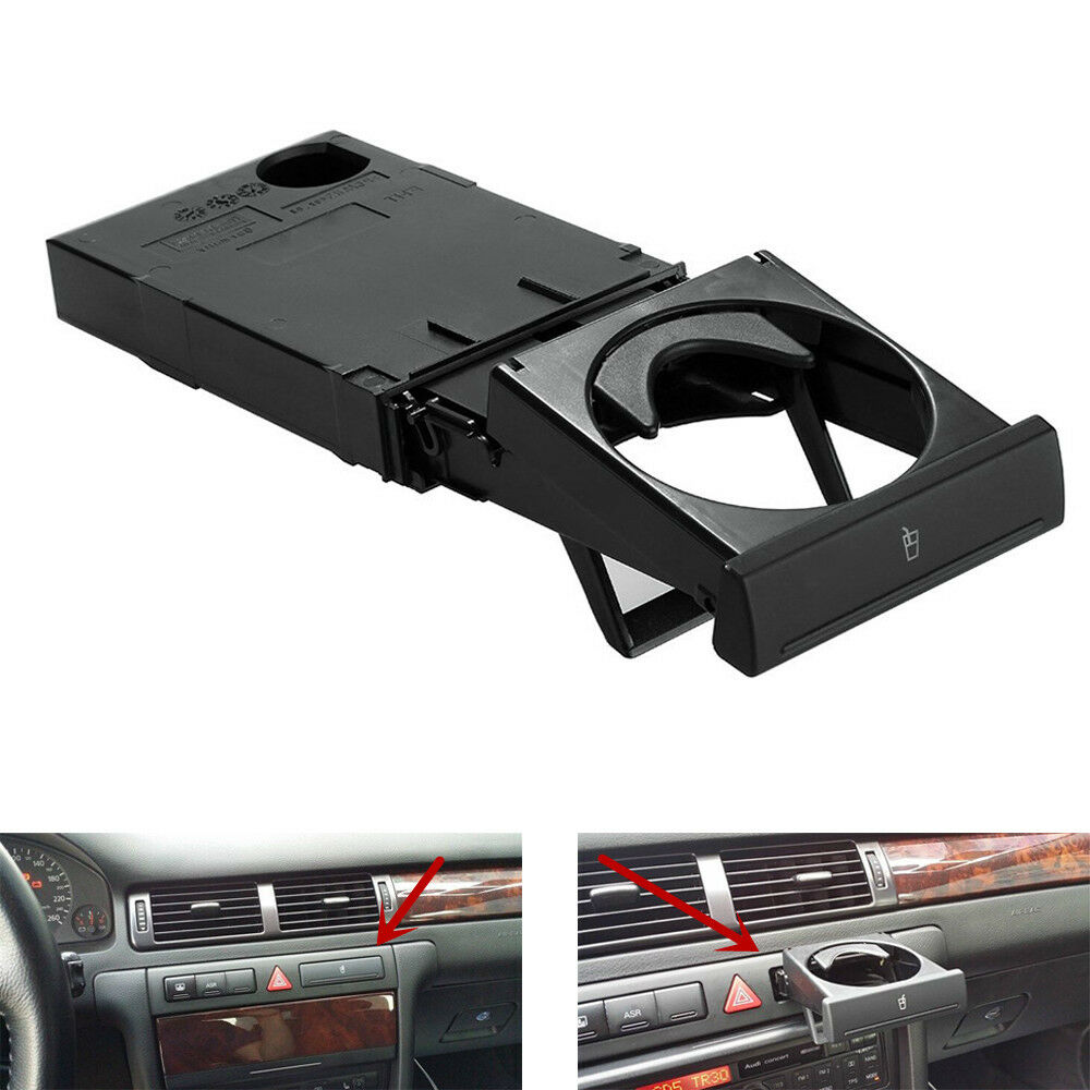
Later, I learned that the limitation is usually depth. The 914 dash pretty shallow by modern car standards and has only about 165 mm depth from the ash tray face to the bulkhead. Most cassette style couple holders appear to be about 185 mm deep so they won't work. Another problem is the angle the ashtray mounts so it slopes to the bottom. Cup holders that pull straight out will end up at a funky slant. Maybe not a deal killer but awkward and not very Feng Shui. The Audi cup holder checked off two boxes by being small enough to fit within the footprint of the stock ashtray and also has a cool spring loaded slider mechanism that pops out and then tilts down so winds up close to level mounted in the 914 ash tray opening. Again, it was simply dumb luck that I found this device in our tiny little salvage yard.

Here's an ebay pic of the unit I got. Mine was missing the decorative face plate. More on that later. The dimension are 3-3/8W x 5-1/2D x 3/4T

IPB Image

Mounting the Cassette

The original plan was to just fab a custom bracket to screw in in place of the ash tray hanger but the small footprint of the Audi cassette opened the possibility of a plug-and-play solution. A couple years ago I bought an extra ashtray from @bandjoey with this project in mind and knowing an ashtray would probably be sacrificed in the process.

The only real challenge is that the ashtray is curved to sweep up at an angle and wind up close to level in the open position. The cup holder cassette, of course, is straight. The solution was to cut the top, front and bottom out of the ashtray to leave just the two sides as rails and the back to hold them together. A new cross piece across the top of the front was fabricated.

Click to view attachment

Then I tacked in a spacer on the front to hold the installed cassette in the right position. When installed, the cassette will rest on the dash face opening for the ash tray. The spacer holds it down so it doesn't pop up.

Click to view attachment

I added a little tab at the rear to support the cassette when installed.

Click to view attachment

When the cassette slides into place the rear will be higher than the carrier like this.

Click to view attachment

To slide the unit in place, you have to pull the cassette forward in the carrier to drop the rear so it will clear the dash opening. Then as the unit slides in, the cassette will slide rearward and up on the tab. The tab is bent to form a little ramp to guide the cassette into place.

Back up front, I added a lower cover plate. This isn't completely necessary since the cassette will be supported by the dash face when installed, but it polishes off the look and helps to solidify the whole thing.

The only other thing needed is to add stops at the front of the slider rail tracks so the unit doesn't slide in too deep. I just ran a weld bead along each side of the front corners and ground them flat. You can kind of see them in the pic of the front spacer.

Finally, the whole thing got painted in satin trim black.

Click to view attachment

Modifying the Cup Holder

There are just a couple small things that need removed from the cup holder. Mine came with a receptacle for a light at the rear and a light guide that ran to the front to an indicator. The receptacle needs to be removed so the cassette will slide all the way to the back of the carrier. I ground mine off but then discovered it just clipped on. I also had to grind off a couple ridges on the face of the drawer but as I mentioned, mine was missing the face plate. This makes a difference in the next step.

I also had to make up some acrylic spacers that I solvent welded onto the drawer front. This was to create a surface to attach the ash tray front in the right position that it is flush with the dash when closed. It has to be done after the ash tray front is sculpted. If the face plate is still attached, I'm not sure if spacers will be needed. You might be able to sculpt the ash tray face to attache directly.

Click to view attachment

Sculpting the Ash Tray Front

I didn't take any pics of this as it was a learn as you go process. You have to hollow out the recess on the back side of the ash tray front to create a flat surface to attach it to the front of the cup holder. You also have to grind down the depth so it will be flush with the dash when closed. You also have to thing the top lip so it will clear the space between the top of the cup holder drawer and padded dash opening. You might also have to remove a small amount of material on the back side of the lip to clear the circle of the cup holder opening. I did all this with a combination of a dremel, 2" angle grinder, belt sander, and oscillating spindle sander. The last was to clear the cup holder circle and isn't necessary. There is a metal frame inside the ash tray front so be prepared for that.

After a lot of test fitting, grinding a little, and more fitting, the ash tray front was attached with 3M Trim Tape.

Another Idea

Back to that Subaru cup holder. It didn't work for the dash install but there is a place I think it would work. It isn't completely stealth, but could be interesting.

Click to view attachment

One reason I'm fascinated with the Forester cup holder is because they also make an interesting two cup version. I found one at the junk yard but it was all busted up and unusable. I did verify that the width is about the same as the 914 ash tray front. These holders also are adjustable for both small and large diameter cups.

Here's the one I have.

Click to view attachment

Click to view attachment

And here's what the two cup version looks like.

Click to view attachment

The single version would fit inside the center cushion for sure and I think the double version would too. It doesn't look like it would interfere with shifting but would block the heater lever a bit. Interesting idea anyway.
bbrock
Shifting gears, I started preliminary setup of the valve train today in the final push to getting the engine back in the car.

I sent the rockers off to bugguy1967 on the Samba to have them machined for swivel foot adjusters. I also had the blocks milled for solid spacers. He supplied the spacers, shims, and adjusters.

Click to view attachment

The adjusters are Thorsten Pieper German made adjusters which have gotten very good reviews including a few of our members here. These are 10mm so fit in the 2 liter rockers and are the same overall length as the stock adjusters so no issues with them banging against the valve covers. Here's the kit ready for assembly.

Click to view attachment

The goal is to set up the shims to align the rockers with the valves and have 0.005" of end float per rocker. I spent over 2 hours figuring out the first set. The rest took about 30 minutes each. I'm not sure my process is correct which is why this is preliminary, but here's how I did it. I started by shimming between the blocks and rockers to center the rocker over the valve stem. I left the adjusters out to sight through the center.

Click to view attachment

Now here is my question that I asked in another thread but no answers yet. I set up the rockers to be dead center over the valve stem. The guy who did the machine work says they should be offset about 1mm from the center line. I know the stock adjusters are supposed to be offset a little but I didn't think this applies to the swivel foot adjusters. I thought an advantage of swivel feet is to apply even distribution of force across the valves stem for less side load on guides and less wear on the stems. Would love to hear opinions on this.

After setting the shims from block to rocker, I then filled in between rockers and the spacer, trying to keep the shims evenly split on each side of the spacer. I noticed that one end always needed a lot of shims due to the amount of material removed from the blocks. Note the stack of shims next to the right block.

Click to view attachment

It seemed excessive so I fetched four unmilled blocks from my spare parts stash and swapped out half of the blocks. that filled in much of the space and seems more reasonable. I think it makes sense to mill only half of the blocks. Again, if anyone sees a problem with this, let me know.

Click to view attachment

After that, the adjusters went in and it is starting to look like a running engine again.

Click to view attachment

Click to view attachment

Once I confirm whether dead center alignment is okay, I'll move on to setting the push rod length following Jake's procedure. I'm going to run aluminum push rods to keep the noise down. It sounds like with this setup, there is a good chance the stock push rods can be shortened and reused. I learned the stock push rods have a .130" wall where the ACN aluminum rods are .080" so it will be nice to stick with the stock push rods.

Once that is sorted, I'll disassemble the rockers for a final cleaning and lubing with assembly lube for final assembly. At that point, the engine will be complete.
Dave_Darling
The adjusters should probably still be offset from the valve tips. That is done to help the valves rotate in their guides, evening out the wear and making everything last longer. I don't know how far they are supposed to be offset, but since the machinist says 1mm I'd be inclined to take him at his word.

--DD
930cabman
QUOTE(Dave_Darling @ Jan 4 2021, 12:24 AM) *

The adjusters should probably still be offset from the valve tips. That is done to help the valves rotate in their guides, evening out the wear and making everything last longer. I don't know how far they are supposed to be offset, but since the machinist says 1mm I'd be inclined to take him at his word.

--DD


+1, I would tend to agree. valve train geometry can be tricky, make sure you get it right
Superhawk996
Looking forward to seeing it fire up for the first time.
bbrock
Had a fun discussion on the other thread about swivel feet and offsets (at least for me). The upshot is that I'll be doing a bit of shim shifting to move the adjusters off center.

Got a few packages today. First up, a couple final details for the seat belts.

Click to view attachment

Also received my Sunset Porsche order of mostly transmission seals and parts. Unfortunately, I think I missed ordering one of the seals for the speedo drive. I also ordered a set of Genuine Porsche master cylinder grommets to replace the ones that came with my 914Rubber MC that allowed my expensive Pentosin brake fluid weep out all over the floor. These grommets are substantially beefier and stiffer than the ones that came with the MC. Really not cool mad.gif

Click to view attachment

A couple weeks ago I repaired the corroded tip on my art hanger. I started by making a cardboard template of the good side.

Click to view attachment

Then flipped it over to make a new tip for the corroded side.

Click to view attachment

Welded it up.

Click to view attachment

and a coat of paint.

Click to view attachment

Why is he calling it an "art hanger?", you ask. That's just goofy. Well, today I received this work of art from @mb911 to hang on it. You have to see one of these in person to see what a true work of art this is. The welds!!! pray.gif It's like he's some kind of high end professional or something.:wink:

Click to view attachment

Yes, this post was really just about showing off the new muffler... that, and getting one post closer to that sub @altitude411 promised. I hope that comes in yellow.

IPB Image
930cabman
Yes, agreed that is art. Does he make these from scratch?
mb911
QUOTE(930cabman @ Jan 5 2021, 03:58 AM) *

Yes, agreed that is art. Does he make these from scratch?


Yes we do and thanks everyone
Cairo94507
Here is Ben's little bit louder 2 in 1 out for the 6:
Click to view attachment
930cabman
I might order one and just hang it on the wall!!
bbrock
The Saturday plan was to replace all the transmission seals. I started by rebuilding the shift console. I started by removing the top shift ball fitting thingy that connects to the shift rod. It was a total PITA, took longer than expected, and I didn't get any pics as a result. Here's a tip. If you have Dr. Evil's transmission rebuild DVDs, watch them and PAY ATTENTION BEFORE taking the console apart. he tells you taking the top ball fitting thingy off is a PITA and don't do it. Instead, remove the toothed fork thingy at the bottom. Yep, that was much easier. Some people just have to learn the hard way. screwy.gif 
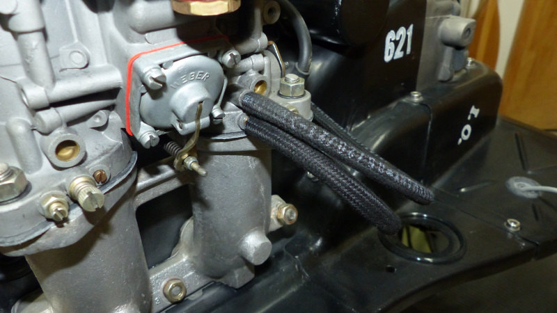
Anyway, one O-ring and seal later and it was back together. Here is the only pic I took after the fact.

Click to view attachment

Then I moved to the bell housing to replace the input shaft seal and rebuild the clutch fork. I pulled off the throw out bearing tube and noticed what looked like a hint of yellow cad around the rim.

Click to view attachment

Flipped it over, and sure enough.

Click to view attachment

That changed the schedule for the day because now I had to dust off the old plating system and make a run to town for some copper wire to hang parts from. Then I did a short plating run including refreshing the T.O.B. Here it is on the bead blasted clutch fork with new ball cup bushing installed and a coat of Boeshield T-9 for protection.

Click to view attachment

Today I finished transmission sealing (almost). The old input shaft seal was the factory installed original with the wide flange on the left and a nice new seal ready to go in. The old seal was brittle as hell and the new seal has a double sealing lip rather than single. Should seal better.

Click to view attachment

And installed. It looks like it is set a little deep in this pic but it isn't. It sits flush with the bottom of the old flange landing per Dr. Evil's instructions.

Click to view attachment

And here is the bell housing with clutch fork re-installed.

Click to view attachment

Next up were the drive seals. Again, the old seal were brittle and just crumbled when the seal puller touched them. Good thing that got replaced.

Click to view attachment

I got to used my fancy little bearing and seal driver set from HF.

Click to view attachment

And a fine job it did.

Click to view attachment

The drive flanges needed a little TLC. They got cleaned and degreased. Then I dipped the flanges in muriatic acid for about 2 minutes dissolve all the rust out of the pores. I polished off the rusty area of the shaft just outside where it rode on the old seal with 600 grit wet/dry and sprayed the flange with T-9. Here is a before/after comparison.

Click to view attachment

That almost completes all the seals but there are a few things missing. I ordered a new backup light switch from Amazon and last week it was delivered to an address in St. Louis blink.gif I've sent two messages to the seller but no reply yet. If I don't hear from them tomorrow, I will request a refund through Amazon and order from someone else. For now, I have a new pin with no place to go.

Also, I have a new O-ring for the speedo drive but did not learn about the gear shaft seal inside until my other seals had shipped. I placed a Pelican order tonight and padded it with extra filters and oil sump gaskets to get free shipping. I also ordered a new speedo angel drive on ebay. My old one has gone missing and I vaguely recall it was shot. Expensive little buggers! Anyway, here's the transmission almost ready to go back into service.

Click to view attachment
bbrock
The T.O.B. tube was not the only reason I fired up the Zinc-O-Matic yesterday. These black wire bale clips on the carb intakes have been bugging the stromberg.gif out of me.

Click to view attachment

MUCH better cheer.gif

Click to view attachment

Click to view attachment

I finished the day putting the car back into its preferred habitat.

Click to view attachment

... and tearing out the rear end. Boy. Had to use a flash on this shot and it sure picked up the dust on the trailing arms icon8.gif

Click to view attachment

Why did I do this? Well... when I built my trailing arms, the only rubber bushings available were from Elephant Racing which I could not afford at the time so I bought a set of poly graphite from 914Rubber along with a set of their SS pivot shafts. Less than a year later they came out with their rubber bushings so the trailing arms would have to come out again. headbang.gif Since I was replacing bushings, I also decided to ditch the SS pivots because they are heavy as a MoFo. Bruce Stone is swapping me straight up for a pair of plated OE shafts. I think that is a very good deal for both of us. I just don't see the point of that much extra weight. I didn't weigh them but am guessing 5lbs. each.

Click to view attachment

Hopefully I'll get the exchange pivots soon and get all this crap put back together. I have a couple other tasks to do while the car is on jack stands though.
Superhawk996
aktion035.gif Totally agree on the trailing arm pivots. No need to add unnecessary weight when originals have worked for 50 years and I'm not aware of many showing signs of fatigue.

Looking great. I'm getting really tempted to get a plating kit. There are so many little items here and there that could use a dip like you've done. Nice work!

I previously used to use the Eastwood Tin Zinc on motorcycle fasteners that are silver but I really like the yellow cadmium look for the German stuff.

What kit did you use? I apologize for asking. I know it's buried in your thread but let's be honest. I can't remember which page and now that you are up to 90 pages, it takes a while to find! laugh.gif
rudedude
Looking at your rocker arm setup are a couple of the end blocks on with the angled surface toward the head? I always thought the flat side went towards the head with the slot towards the pushrod.
bbrock
QUOTE(rudedude @ Jan 11 2021, 07:33 AM) *

Looking at your rocker arm setup are a couple of the end blocks on with the angled surface toward the head? I always thought the flat side went towards the head with the slot towards the pushrod.


I think it is just goofy lighting from the camera flash. All of the slots are pointing toward the pushrods.

@Superhawk996 I'm using the Caswell system.
bbrock
QUOTE(rudedude @ Jan 11 2021, 07:33 AM) *

Looking at your rocker arm setup are a couple of the end blocks on with the angled surface toward the head? I always thought the flat side went towards the head with the slot towards the pushrod.


Edit: Oh. I see what you are looking at now. Yes, some of those blocks will get flipped around the right way in final assembly. I was just looking at spacing for the shims here... which will also get shifted around to add some offset to the adjusters.
bbrock
This Tranny is Ready to Grind

Finished up the transmission today. Still not sure how my backup light switch ended up in St. Louis but the vendor refunded my $ since they didn't have anymore in stock and I ordered from another source. So that was first on the list this morning. Here's the switch and a new pin from Porsche.

Click to view attachment

Pretty straight forward. First clean out your bunghole.

Click to view attachment

Insert pin.

Click to view attachment

Torque the switch to 23-29 ft-lbs.

Click to view attachment

And done.

Click to view attachment

Next up was the speedo drive. Luckily there was a recent thread on this or I would have been scratching my head all day on how to get that little seal out. The solution is genius. Pop out the special metal washer with a pick. Then thread an M14 or 9/16 bolt into the old seal. Then knock it out from the other side with a drift. Easy peezy.

Click to view attachment

A thin coat of Vasoline on the new seal and it pretty much goes in with just thumb pressure. I did use a 12mm socket and a couple light taps to fully seat it.

Click to view attachment

Then the special little washer goes back in. it goes in with thumb pressure and then I use the back side of a pick to make sure it was seated.

Click to view attachment

Now a new O-ring. Here's a tip. When you get out your bolt organizer to find a bold to pull the seal, don't accidentally toss the O-ring in there when you stow it away. I don't want to say how much time I wasted today looking for that little dickwad.

Click to view attachment

Nestled in nice and snug.

Click to view attachment

Last thing was to add a new VDO angle drive.

Click to view attachment

All new seals on the tranny now. Only thing left is to protect the case Porsche-style. Those who have followed this misadventure from the beginning may recall this from There are a few threads on this here and on the Bird. Apparently the engine and trans were coated with Tectyl when they left the factory.

Click to view attachment

Tectyl is a lot like Cosmoline but if Porsche used Tectyl, that's what I use too. My hunch is that it was mainly intended to protect the mag during the trans-Atlantic trip and not much more, but someone on Pelican claimed there was a tech bulletin suggesting to refresh the Tectyl on transmission cases every couple of years to keep them protected. It doesn't matter. I'm after the new car experience so whatever toxic stench this throws as it bakes off, I want it.

Click to view attachment

It was apparently sprayed on originally but I just daub it on with a cheap sponge brush. Over the next few weeks this will dry to a semi-hard waxy service with a light amber tint that says, "I'm loved by a crazy person."

Click to view attachment
oldie914
Porsche's advice on Tectyl was correct. The Germans used an unblievable amount of salt on the roads in the early 1970's and cars on the autobahn were in a salt bath all winter long. Rule of thumb was two windshield washer water tank fillups per tank of gas.
Superhawk996
QUOTE(bbrock @ Jan 16 2021, 09:39 PM) *


Pretty straight forward. First clean out your bunghole.
I'm after the new car experience so whatever toxic stench this throws as it bakes off, I want it.


lol-2.gif It's funny because I hate new car smell.

Thanks again for your leftover Tectyl from summer -- it will go to good use on the 911 mag case one of these days when it get's final assembly.


bbrock
@914_7T3

A couple pages back I mentioned a problem with one of the distributor vacuum hoses.

IPB Image

This clearly needs to be fixed if I'm to have ANY hope of a smooth running engine. Ah yes, much better biggrin.gif

Click to view attachment

AFAIK, colored vacuum hoses are NLA. There is at least one thread asking if anyone had tried bleaching black braided hose and re-dying it the right color. The answer to that now is yes, and the answer to whether it works is NO! I tested a small scrap of new German Continental (OEM) hose in some bleach left overnight. What you get is a bare naked rubber hose with a bunch of still very black braid cloth fibers floating ghoulishly in the swill. Absolute fail.

I started exploring fabric paint. Most of them are very translucent and intended to go on a white, or very light fabric. The consensus is that you can only make things darker with it. Then I found Jaquard Neopaque opaque fabric paint.

Click to view attachment

Reviews sounded promising. I ordered a small jar each of green, red, and russet. The manufacturer web site has online color chips that suck so it was really hard to tell what color I would get between red and russet so had to order both and figured I might need to mix paints to get the right color.

I cleaned up the remnant of original red hose I had as best I could and ran some tests. The red was pukey bright. It would look great on a "My First Pony" t-shirt for a 6 year old girl, but not in a 914 engine bay. The Russet by itself looked pretty good to me trying, to account for 48 years of fade on the original hose. From bottom to top in the below pic is Red (air brushed), original remnant, Russet (sponge brushed), and the unpainted braided hose.

Click to view attachment

I tried to get fancy with my cheapo HF air brush but you have to dilute the paint so much it would take forever to build up the pigment. Instead, I applied with a sponge brush, working it into the braiding. It takes a 2-3 layers. The paint looks too thick when it first goes on but then soaks into the fabric and darkens. After it was dry (and even before), I used a stiff nylon brush pretty aggressively to smooth out the finish and pull up the cloth fibers so they weren't all stuck and matted. The end result was the cloth braiding a little stiffer feeling than the unpainted hose but close to the old hose that had seen plenty of heat cycling over the years. The hose itself is still flexible like new hose.

For the green, I didn't have an original sample so just went with straight green. I suspect it is a little brighter than the original but close enough for me.

Click to view attachment

Here are some pics of the end result. No doubt the engine will breath and run much better with the proper colored hoses attached. laugh.gif

Click to view attachment

Click to view attachment

Click to view attachment
bbrock
QUOTE(Superhawk996 @ Jan 17 2021, 09:40 AM) *

QUOTE(bbrock @ Jan 16 2021, 09:39 PM) *


Pretty straight forward. First clean out your bunghole.
I'm after the new car experience so whatever toxic stench this throws as it bakes off, I want it.


lol-2.gif It's funny because I hate new car smell.

Thanks again for your leftover Tectyl from summer -- it will go to good use on the 911 mag case one of these days when it get's final assembly.


@Superhawk996 , are you implying with your creative editing that my bunghole throws off toxic stench? Not true... because I cleaned it. lol-2.gif
Superhawk996
happy11.gif

Click to view attachment

Superhawk996
Totally awesome work on the hose coloration. Very entertaining and practial too. Really will help make sense of the maze of hoses that can inhabit the 914 engine compartment. Even worse with FI.

The creativity and compulsion to innovate never cease to amaze. aktion035.gif
bbrock
QUOTE(Superhawk996 @ Jan 17 2021, 01:54 PM) *

Totally awesome work on the hose coloration. Very entertaining and practial too. Really will help make sense of the maze of hoses that can inhabit the 914 engine compartment. Even worse with FI.

The creativity and compulsion to innovate never cease to amaze. aktion035.gif


You are suggesting there is practical value to this madness? wacko.gif

Try to rationalize this one, and tread lightly because you know you are an accomplice here.

With carbs, the bunghole (had to sneak that word in again happy11.gif ) for the CHT is unused.

Click to view attachment

This was bugging me because I may have a plan for that for a possible future project. I don't want it to be filled with crap.

With the help of @Superhawk996 , I sourced an M10x1.0 drain plug. I gooped up the head with grease to stick it to my socket, and put a smear of anti-seize on the threads.

Click to view attachment

I snugged it just barely past finger tight and that is one nice little bunghole plug.

Click to view attachment

Then the grommet.

Click to view attachment

If this isn't a cry for help, I don't know what is. screwy.gif But it's the details that count. shades.gif
raynekat
QUOTE(Superhawk996 @ Jan 17 2021, 12:54 PM) *

The creativity and compulsion to innovate never cease to amaze. aktion035.gif


I'd say that hits the "nail" in the coffin or on the head. Ha

Can't say in my wildest mad scientist dreams I ever considered dying the fabric braided lines in my car.
Brent ascends to such lofty escarpments that us mere mortals can only wishfully fantasize about....
He is definitely of a land of a "different height." wink.gif

bbrock
QUOTE(raynekat @ Jan 17 2021, 08:15 PM) *

QUOTE(Superhawk996 @ Jan 17 2021, 12:54 PM) *

The creativity and compulsion to innovate never cease to amaze. aktion035.gif


I'd say that hits the "nail" in the coffin or on the head. Ha

Can't say in my wildest mad scientist dreams I ever considered dying the fabric braided lines in my car.
Brent ascends to such lofty escarpments that us mere mortals can only wishfully fantasize about....
He is definitely of a land of a "different height." wink.gif


Ha! It might be your fault. I think you unleashed a monster with the flocking. beerchug.gif
914_7T3
QUOTE(bbrock @ Jan 17 2021, 12:05 PM) *

@914_7T3

A couple pages back I mentioned a problem with one of the distributor vacuum hoses.

IPB Image

This clearly needs to be fixed if I'm to have ANY hope of a smooth running engine. Ah yes, much better biggrin.gif

Click to view attachment

AFAIK, colored vacuum hoses are NLA. There is at least one thread asking if anyone had tried bleaching black braided hose and re-dying it the right color. The answer to that now is yes, and the answer to whether it works is NO! I tested a small scrap of new German Continental (OEM) hose in some bleach left overnight. What you get is a bare naked rubber hose with a bunch of still very black braid cloth fibers floating ghoulishly in the swill. Absolute fail.

I started exploring fabric paint. Most of them are very translucent and intended to go on a white, or very light fabric. The consensus is that you can only make things darker with it. Then I found Jaquard Neopaque opaque fabric paint.

Click to view attachment

Reviews sounded promising. I ordered a small jar each of green, red, and russet. The manufacturer web site has online color chips that suck so it was really hard to tell what color I would get between red and russet so had to order both and figured I might need to mix paints to get the right color.

I cleaned up the remnant of original red hose I had as best I could and ran some tests. The red was pukey bright. It would look great on a "My First Pony" t-shirt for a 6 year old girl, but not in a 914 engine bay. The Russet by itself looked pretty good to me trying, to account for 48 years of fade on the original hose. From bottom to top in the below pic is Red (air brushed), original remnant, Russet (sponge brushed), and the unpainted braided hose.

Click to view attachment

I tried to get fancy with my cheapo HF air brush but you have to dilute the paint so much it would take forever to build up the pigment. Instead, I applied with a sponge brush, working it into the braiding. It takes a 2-3 layers. The paint looks too thick when it first goes on but then soaks into the fabric and darkens. After it was dry (and even before), I used a stiff nylon brush pretty aggressively to smooth out the finish and pull up the cloth fibers so they weren't all stuck and matted. The end result was the cloth braiding a little stiffer feeling than the unpainted hose but close to the old hose that had seen plenty of heat cycling over the years. The hose itself is still flexible like new hose.

For the green, I didn't have an original sample so just went with straight green. I suspect it is a little brighter than the original but close enough for me.

Click to view attachment

Here are some pics of the end result. No doubt the engine will breath and run much better with the proper colored hoses attached. laugh.gif

Click to view attachment

Click to view attachment

Click to view attachment


pray.gif

That is all!
doug_b_928
Wow, Brent. The hoses look fantastic. I didn't know they were supposed to be red and green; very cool.
bbrock
In case y'all haven't had anything to roll your eyes at lately, I should probably update on last weekends shenanigans. Had a non-Porsche project to work on so just did a few small jobs. First up was finishing a detail on the world's most awesome Type IV carb intakes. Last item was to provision for connecting the charcoal canister circuit and oil breather to the intake. There was already a port on for the vapor line but it was oversized. I thought it would be easy to source a 1/4" black plastic fitting to cut nipples from but I was wrong. I searched all the home improvement and hardware stores with no luck. Couldn't find anything on the Internets. Finally had to order it from McMaster. Even there, the selection was slim and I had to order a tubing that comes oversized with thick walls intended to be machined to size. I was looking for about 1/2" to fit the 12mm hose. Not have room in the shop for a lathe, I improvised by chucking the tubing in a 1/2" drill, clamping the drill in a vice, and sanding the tube down to get the right OD, and then drill out the ID. I should have gotten a pic to document what a dipshit I am, but here's a pic of the final product.

Click to view attachment

Similar "drill" (get it? happy11.gif ) for the oil breather. The original air cleaner had the breather port attached to one of the side ducts. I assume these are separated from the filter to prevent the oily vapor from fouling the filter element. That port, of course, was lost when I swapped them for my custom jobbies. Of course I stupidly forgot to weld in a steel tube on one of the ducts so had to go to plan B which was to install a tube on the plastic part of the side duct. I put it in at an angle to direct the vapor toward the carb (just like the original) and attached it by "welding" it in with an old soldering iron and a scrap of black zip tie. Strong as hell.

Click to view attachment

Here's how much tube I had to buy for those two little dinkass nipples.

Click to view attachment

Next was finally fitting up the fuel pump. I've been waiting over 2 months for this NOS boot to arrive from Latvia.

Click to view attachment

The fuel pump wires I ran in the harness were about 4" shorter than I would have preferred but that 4" would have been pretty expensive so I decided to roll the dice. Luckily, it managed to work. I ran out of good omega fuel hose clamps so this will have to be just a dry fit. Before you say anything about not being able to run a factory pump with carbs... sure you can. You just have to design the system for it. That's all on that for now.

Click to view attachment

Everything fits nicely behind Door #1.

Click to view attachment

To make sure I don't forget about those missing hose clamps, I yellow-tagged the fuel filler so I don't start dumping fuel in the tank and make for a bad day.

Click to view attachment

Now for the eye-rolling... I don't know if you've noticed, but there is a little plastic bushing that the windshield wiper arm spring connects to. This is a horrible pic because I painted it black when refurbing the arms.

Click to view attachment

Mine crumbled to dust so needed replaced. I bought a Delrin rod from McMaster for stock and cut discs to about the right width and fine tuned the width by running them over sandpaper on a flat surface.

Click to view attachment

I used the wiper arm as a jig to mark the disc close to center with a hand drill, and then drilled the center hole on the drill press.

Click to view attachment

Next, I mounted the disc on a Dremel cutting disc arbor and chucked it in the drill press. I "turned" the disc down to the right OD using sandpaper on a paint stick.

Click to view attachment

Now for the fun part - forming the groove for the spring hook. I tried several things that didn't work so well. What did work was a 6d finish nail, heated to my favorite flavor, cherry red.

Click to view attachment

After quite a bit of back and forth, forming and test fitting, I had a nice little pulley shaped bushing.

Click to view attachment

Here's one nestled in its home.

Click to view attachment

Now the not so fun part. Before trying to put the springs back on, eat your damn Wheaties. Those things were a Bee-otch to pull on. I'm could have rigged up some kind of lever jig to make it easier, but I manage to grunt those buggers on. And here they are.

Click to view attachment
Van914
Impressive!
Superhawk996
QUOTE(bbrock @ Jan 26 2021, 10:04 PM) *


Everything fits nicely behind Door #1.


My pump is going up front for vapor lock reasons but I've never liked any of the front mount solutions.

For some reason that space below the head lamp buckets is just wasted space and begging for something to go there but then the hose routing get's all whacky. Getting the pump noise further from the cabin would be a good thing.

I don't know why, but, for some reason cuttting a hole in my front bulkhead rubs me the wrong way. But, the more I look at this it's becoming more appealing. Of course, the front bulkhead location was an OEM solution for obvious reasons laugh.gif

By the way do you ever sleep? lol-2.gif
bbrock
QUOTE(Superhawk996 @ Jan 27 2021, 07:31 AM) *

QUOTE(bbrock @ Jan 26 2021, 10:04 PM) *


Everything fits nicely behind Door #1.


My pump is going up front for vapor lock reasons but I've never liked any of the front mount solutions.

For some reason that space below the head lamp buckets is just wasted space and begging for something to go there but then the hose routing get's all whacky. Getting the pump noise further from the cabin would be a good thing.

I don't know why, but, for some reason cuttting a hole in my front bulkhead rubs me the wrong way. But, the more I look at this it's becoming more appealing. Of course, the front bulkhead location was an OEM solution for obvious reasons laugh.gif

By the way do you ever sleep? lol-2.gif


I'm with you. I've had two 914s (including this one) with the fuel pump relocated to the steering rack area per factory tech bulletin. Neither was done with finesse but the location worked fine even though it looked like the after thought that it was. The one 914 I had with the fuel pump still in original location vapor locked quite frequently. Cutting a hole in the bulkhead was difficult for me, but in the end, I decided it was the right and proper relocation position.

I haven't decided what to do with the bulkhead carpet yet. For now I just left it unglued in that area so it drapes over the blister for a stealth upgrade. I probably should source the little carpet blister to add so I can glue the bulkhead carpet down properly and still access the pump.
Dion
Fantastic! Just fantastic work mate. Keep it coming. beerchug.gif
bbrock
Myth Busting

I'm convince that Internet myths are impossible to kill, but it sure is fun to try. Today's myth is that you can't run carbs with a high pressure FI fuel pump. Nonsense. Lots of people do it and there are several good threads on it. The trick is to use a return line and bypass fuel pressure regulator. And no, it does not mean you are pressurizing part of your fuel circuit to 30 psi or whatever the pump is rated for. Pumps don't make pressure. Regulators do. For Webers, you install a bypass regulator that will bleed off enough fuel to make 3-4 psi and dump the rest into the return line where it feeds you reserve fuel reservoir the way Porsche intended. Do you have to set up carbs this way? Of course not. Are there benefits? Yes.

So this was my task today - installing the regulator. Low pressure bypass regulators are not very common. The most used unit is the PMO regulator which seems to be the standard for Porsche carb conversions.

IPB Image

There is also Malpassi which is Italian and seems to be pretty commonly used in Europe. Aircooled.net recommends this brand but did not have the bypass version in stock so I ordered one on ebay from Germany. The two regulators cost about the same once you figure buying a separate pressure gauge for the Malpassi. To be honest, my decision was based purely on aesthetics. The PMO is a nice unit but screams after market whereas the Malpassi seemed like it would look more native to a 73 Porsche engine bay.

First step was to modify the little bracket that came with the unit. I bent it 90 degrees. Then I drilled out the mount holes to repurpose my original MPS mounting grommets for an anti vibration mount. I don't want the regulator telegraphing fuel pump vibrations into the chassis.

Click to view attachment

The bracket bolts to the MPS bracket on the chassis. Here's the view of the regulator mounted from above.

Click to view attachment

And from inside the engine bay. The hose coming out of the bottom is the return loop. Still need to pick up some good hose clamps before the permanent installation, but I like how this looks. After trying a lot of different locations, I decided to mount the pressure gauge on the right carb with a tee fitting which has been ordered.

Click to view attachment

The other thing I did today was to shift shims around on my rocker shafts to offset the adjusters slightly on the valves stems. I'm still quite skeptical it makes any real difference, but can't argue with the fact many reliable engines have been built with the offset.

Click to view attachment

Just before quitting for the day, I snapped the pushrod tube retaining springs in just to get them off my table saw and discovered one of them looks pretty sketchy. It is worn right where it would contact the edge of one of the center blocks when snapped in place. Having that snap in a running engine doesn't sound like fun. I have a tub full of 3 engines worth of spare valve train parts but not a single retaining spring. How can that be? confused24.gif I'll have to source a good used one.

Click to view attachment
bbrock
Ground Hog Day

I spent this weekend redoing crap I've already done. I started a separate thread about my trailing arm bushing saga, but just to recap... Early in the build I bought 914Rubber's solid SS pivot shafts and poly/graphite bushings since that was the only option I could afford at the time. Then when 914R introduced their new rubber rear bushings, I jumped onboard. In the process of tearing down the trailing arms to install the new bushings, I decided the solid SS pivots were too damn heavy for a street car so swapped them for a pair of OE shafts. Then I discovered the fit of the bushings was not acceptable. I wound up doing what I should have done from the get go which is ti buy Elephant Racing bushings. Comparing Elephant with 914R, you can see that the walls of the 914R bushing (left) and the ID larger than Elephant. Measurements are on the other thread.

Click to view attachment

It took a lot of cranking on a pipe clamp to get the Elephant bushing in, but I managed even though my arm has been feeling it all weekend.

Click to view attachment

The result is a super tight fit just like OE.

Click to view attachment

While the trailing arms were out, I installed the rear axles too.

Click to view attachment

Between the rubber bushings that don't allow the outer mount bearing to pivot and the axles in place, reinstalling the trailing arms was quite a bit harder than before and required a copious amount of swearing. This won't look any different to you, but it sure does to me. So happy to have good OE style bushings in place.

Click to view attachment

Next up was to lift the front onto jack stands to tackle a project I've been dreading. After filling and bleeding my brake system to a nice hard pedal, I was sickened to see my fluid reservoir slowly drain dry. I was fairly certain it had seeped past the MC grommets so I ordered new OEM grommets from Porsche a couple months ago. The inside of the gravel pan confirmed my diagnosis. I'm so happy I get to sand that down and repaint.

Click to view attachment

I was suspicious of the grommets that came with the 914R MC from the beginning because they were not nearly ad difficult to install as descriptions I've read. I also noticed when bleeding the lines that if I pushed the supply lines sideways at all, fluid would come out of the grommet. I should have stopped right there. Oh, and yes, the MC does have new metal washers from Porsche in it. A comparison between the 914R grommet with the OEM version raises concerns. Overall the 914R grommets looks to be a close replica of OE except the ID is considerably larger. The ID of the OEM grommet measured 7.16 mm while the 914R version measured 7.5 mm.

Click to view attachment

I can't say if the larger ID was caused by being installed for almost a year, but the OEM grommets took noticeably more force to slip over the flared steal fittings which I did after lubing them inside and out with brake assembly lube.

Click to view attachment

I used an 11mm flare nut wrench to pull the grommets down into the MC. The connection seems MUCH firmer and secure than the old grommets did. So far, no leaks. I'll leave the car on jack stands with no gravel pan for a week to monitor, but I'm optimistic.

Click to view attachment

I'm curious if anyone else has had issues with the 914R grommets leaking. I'll be honest, I was in a bad mood most of the day over this. Anyone who has done this can attest it is no fun to do once, let alone a second time to replace shitty grommets. Worse, keeping brake fluid in the system is kind of important so if there is a defect here, we need to know. The OEM grommets are not expensive so I don't see any reason to use repops anyway.

There was something good that came out of this though. While under the car I found this fuel hose hanging free and the connection is is supposed to connect with.

Click to view attachment

Click to view attachment

I had completely forgotten that I ran out of hose clamps working on those lines so left that last connection undone. I use those yellow tags to make sure I don't forget things like that but they only work if you actually used them slap.gif Proper hose clamps were installed and the connection made.

Click to view attachment

Those 3-port fuel pumps do make a mess of the fuel line routing, but a hundred bucks for a new pump seems unnecessary when the one I have functions well. I may wind up regretting that, but it's how I'm going to roll.

Anyway, not the most fun weekend on the project but a bad day today with the MC grommets may have averted a worse mess in the near future. Here's hoping the brake fluid leak is fixed. hands.gif
Superhawk996
popcorn[1].gif

Getting so close to having a functional vehicle.
930cabman
QUOTE(Superhawk996 @ Feb 8 2021, 09:59 AM) *

popcorn[1].gif

Getting so close to having a functional vehicle.


Keep the momentum going, don't lose track of the finish line
bbrock
Let the car sit for a week to make sure the brake MC grommets held. No leaks!! cheer.gif I can't say for sure if the problem before was my installation or the 914R grommets, but OEM Ate grommets are available and not expensive so why use anything else? confused24.gif Anyway, I finally got to try out me Motive brake bleeder. Worked great. Pedal feels pretty firm. I'll need to bleed them once or twice more after the car has been driven to shake any remaining bubbles loose, but it will do for now. For some reason my brake lights are sticking on unless I release the peddle fast. Hopefully the switch just needs some adjustment but I'll have to track that down.

Click to view attachment

I also resprayed the gravel pan and reinstalled. No pics.

Today was valve geometry day. I made an adjustable push rod out of a spare and followed Jake's procedure. I'm hopefully I can stick with the stock push rods because they are aluminum (quieter than chromoly) and thicker walled than what is available aftermarket. The guy who machined my rockers can also shorten stock push rods, so it was worth a try - hence the adjustable stock push rod. I made a plate to screw to one of the rocker assembly posts that I could attached my crappy HF magnetic base to.

Click to view attachment

As Jake says in his procedure, it is a fiddly process that takes patience. I started with the push rod set at 271mm as suggested. The valve lift on my Elgin cam is .385 for intake. Lift with the 271mm rod measured at .392. Not bad. Jake says to try to get as much lift as you can within 5% of the card spec. which makes the max allowable lift being .404 . After some trial and error, I found by lengthening the rod a bit, I could get as high as .399 so I stopped there and moved to the geometry part. I didn't like the geometry at half lift so dialed back the rod length a bit. With a bit shorter rod, the rocker looked parallel to the valve and I was still getting .389" of lift. Not bad.

Click to view attachment

The push rod measured 271.5. The stock push rods are 270mm which meant I wouldn't be able to use them. That meant I would have to start over with an adjustable push rod with the same tip as would be installed after cut. For grins I decided to throw a stock 270mm rod in and see what it did. To my surprise, the lift was still .389" and the geometry at half lift looks just as good as with the longer rod. It also leaves a little more adjustmen on the screws piratenanner.gif

Click to view attachment

Tomorrow I will set the exhaust rod length. If it checks out at 270mm or less, I think I'll stick with the stock rods. Stronger, cheaper, and easier than having to buy and cut new ones. I'll also follow up using a sharpie and the original adjusters as another check on the sweep just to make sure things look good. It sure would be nice if I wind up being able to pop the old rods back in and call it a day!
euro911
Just got around to catching up on your progress, Brent. Your custom air box fabrication is over the top aktion035.gif

Looking forward to the video (more so the audio) showing us the reduction in intake decibels popcorn[1].gif
bbrock
Thanks Mark. I'm looking forward to those measurements too!

I finished up the valve geometry today. I decided to start the exhaust valve measurement with a stock pushrod to get a baseline. My cam spec is .370 valve lift on the exhaust and with the stock rod, I got .368 Very close and well within 5% of the card spec (actually only .05% short). Here's a better shot of the rig using the very crappy HF magnetic gauge stand.

Click to view attachment

The geometry at half lift looked pretty good too. This was looking promising.

Click to view attachment

I then installed the adjustable rod to see how much lift I would be leaving on the table if I stuck with the stock rods. I was not able to get anything larger than .368 lift at any rod length which was actually a relief to be honest. Then I installed stock rods on both intake and exhaust of #1 cylinder and install the stock adjusters to check the sweep pattern.

Click to view attachment

The pattern looks good, but to be honest, I think there is some voodoo here which is a carry over of my skepticism about offsets. Everyone says you are looking for a sweep that runs across the center of the valve stem, but where the adjuster sweeps is going to be influenced pretty strongly by how much offset you shim the rockers for. Anyway, mine seem to look pretty good. Just a tiny hair off center in the direction I shimmed for offset.

Click to view attachment

I'm pretty sure if I switched my rocker shims back to place the adjusters dead center, it would put the sweep pattern dead center too. So what are we looking for, center sweep or slightly offset adjusters? Whatever, I think it all looks good so I'm happy to just reuse my stock pushrods.

The only thing that kept me from completing final assembly of the valve train was lack of a tube of this stuff:

IPB Image

I was fully expecting to have to either send my OE rods to be shortened, or purchase a new set to cut to length, so I wasn't in a hurry to order. I'll take care of that today so I can button this engine up. In the meantime, I loose fit the pushrod tubes and the rods to keep crap out of the engine, keep all the parts in one place, and have a chance to admire getting close to a finished engine. I still need to source a replacement tube retainer spring too.

Click to view attachment

bbrock
Took some time off to do a little X-country skiing. It is finally looking like winter here. Such a strange year. I'm so lucky to live where I can literally ski right out of the front door.

Got back in time for one last task to update - securing fuel lines. My research says this is the stuff to use for sealing fuel line fittings.

Click to view attachment

That stuff is messy to work with. I was expecting something more like pipe dope. Nope, it is a runny liquid that then dries tacky after applied. I should have put down some cardboard to catch drips because it is a pain to clean up. Anyway, got the pressure regulator fittings sealed and snugged up and attached the hoses with good clamps.

Click to view attachment

Then up front to clamp the hoses on the fuel pump. I forgot to pick up an inline filter to put in front of the pump when I was at the FLAPS getting the clamps screwy.gif That means I'll have to get in here again but it is progress.

Click to view attachment

Got the O-ring sealant, 4 quarts of break in oil, and a fitting to mount the fuel pressure gauge on a carb ordered. I'm going to order a reman Bosch starter at Napa when I'm in town for the dog's vet appt. tomorrow. Inching closer... popcorn[1].gif
Cairo94507
I am glad to see that you have the correct clamps for fuel lines instead of the typical hose clamps which cause leaks.

Just last week, my cousin and I were having coffee at Peet's and he brought his new to him Toyota Land Cruiser, a '75 with a 350 Chevy in it. As we drank coffee a fuel line began leaking. From where we were seated we smelled it and then went and opened the hood. Yup, typical hose clamps on rubber line cut right through the line and was now dripping. 30 minutes later new line and proper clamps and problem solved. We don't need any engine fires. beerchug.gif
Superhawk996
QUOTE(Cairo94507 @ Feb 16 2021, 09:54 AM) *

Toyota Land Cruiser, a '75 with a 350 Chevy in it.


Just can't get over the uniquely American perspective that everything can be improved by putting some sort of V8/SBC/LS in it. lol-2.gif

Thank God that Brent stayed on the straight and narrow path.
Dion
Looking fantastic Brent. I like the sealant idea. Great research on your part. As usual your thread is a wealth of knowledge. Quick question:
What fuel clamps are you using? Source? I need a bunch for my carbs. Also my next project on the car is placing the fuel tank back in, running lines etc.
As Cairo said , don’t need any fire!
Cairo94507
@superhawk996 - Yeah, he bought it 3 weeks ago from a guy in Montana and it came that way. He is still trying to decide if he is going to leave it or put the straight 6 back in it. However the V-8 fits with tons of room to spare and runs great.
bbrock
QUOTE(Dion @ Feb 16 2021, 05:47 PM) *

Looking fantastic Brent. I like the sealant idea. Great research on your part. As usual your thread is a wealth of knowledge. Quick question:
What fuel clamps are you using? Source? I need a bunch for my carbs. Also my next project on the car is placing the fuel tank back in, running lines etc.
As Cairo said , don’t need any fire!


Thanks man. I wish I could give a better answer on the clamps, but I just went to my FLAPS (O'Reilly) and told them I needed the "good" fuel clamps that are omega shaped with the rolled edges that don't cut the hose. They knew exactly what I was talking about and grapped a box from the back room stock shelves (not the aisles). The box says Master Pro Select if that helps. However, the clamps I got from @Rotary'14 when I bought my SS lines from him are better because they have phillips screws rather than slotted like these. I find slotted screws on hose clamps a big PITA. It might be worth checking with him.
This is a "lo-fi" version of our main content. To view the full version with more information, formatting and images, please click here.
Invision Power Board © 2001-2024 Invision Power Services, Inc.