That split stuff is way more expensive than the expanding stuff I used. I tried to find more of it when I was doing it but I just didnt like how it rolled. Also it needed to be tied or taped every foot or so to keep it from rolling out.
Im sure Chris will find an elegant solution to this issue
It is MUCH easier to use than the stuff I used though as you dont have to worry about getting everything right before you put connectors on.
@Andyrew Yep, you nailed it: it's waaaay easier to do the loom wrapping afterwards. I used your expanding / non-split stuff on the injector harness and I really liked it but I'm going with the split on the rest of the harness. With most of the harness hidden, I think it'll look and work just fine.
tygaboy
Jul 2 2020, 03:59 PM
OK, here's V1 of the loom wrap. Not bad, but: There are 2, 3 or 4 20 ga wires in each of those leads that go to the connectors and I think there's a smaller diameter version of this wrap that will take some of the visual bulk away so I may try and source that and give it a try.
Again, not bad and I can live with it until / unless I find something that's a better fit.
tygaboy
Jul 2 2020, 04:01 PM
Before/after. Admittedly, I have to add the passenger side injector harness but, I'd say it's a bit tidier than what I started with, eh?
djway
Jul 2 2020, 07:06 PM
To anyone out there looking at all this on your phone, put it down and go to your computer. This car is too beautiful to waste on a small screen.
tygaboy
Jul 7 2020, 10:50 AM
In no way is my stuff comparable, but I do agree with Singer that "Everything is important".
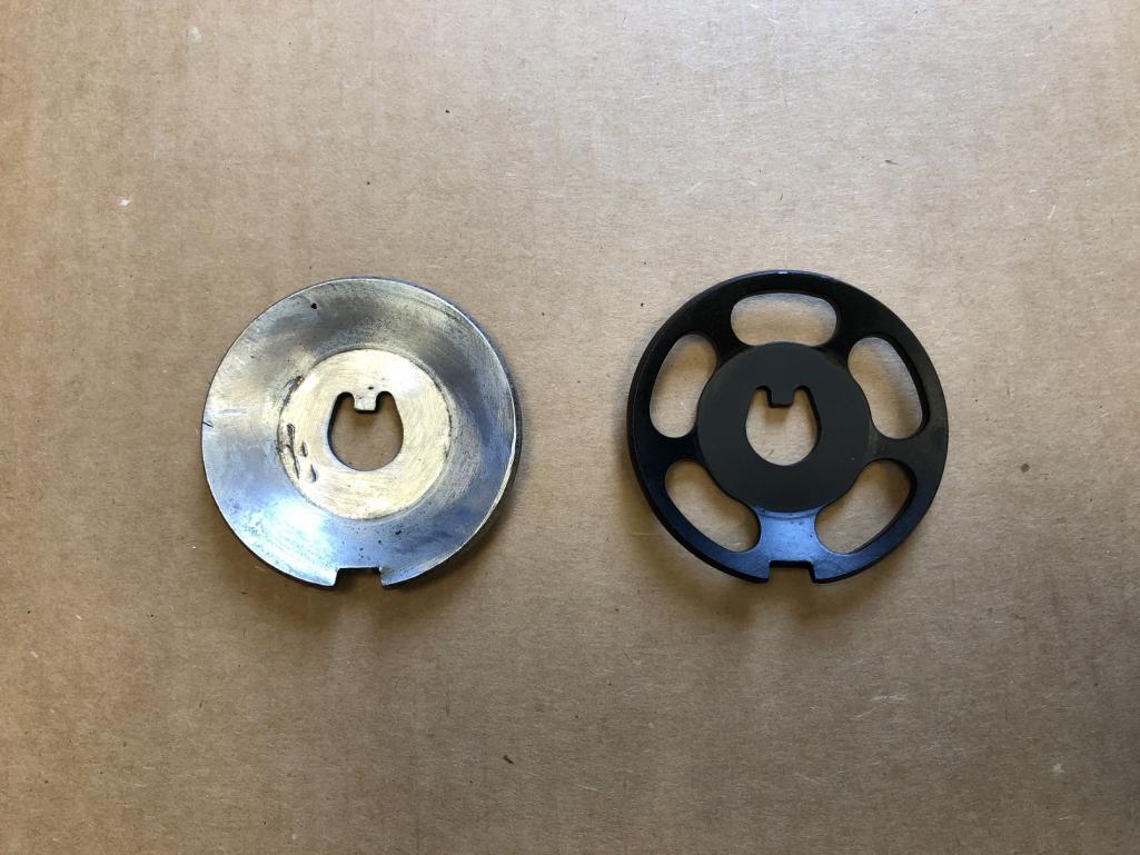
So if you have to make a spacer for the MAT sensor, why NOT take a little extra time to add some style points and make it tapered vs plain?
76-914
Jul 8 2020, 08:33 AM
That looks good. Did you turn that, Chris?
bbrock
Jul 8 2020, 06:20 PM
So life has gotten in the way and it has been a few weeks since I checked in on what the master fabricator was up to. I click on the last page of the thread and this pic fills my screen. So many thoughts... so many words rushing through my head... but really, what CAN be said? This pic says it all.
tomeric914
Jul 8 2020, 09:42 PM
Probably way too late now and kind of a PITA to use unless you plan ahead, but I use what is referred to as "Chemical-Resistant Tube Sleeving" from Mcmaster. It's the closest thing to what the 914 wiring harness is in.
OK, so maybe not that exciting to most of you but this is the first sign of life in the chassis since I've owned it!
I completed the tail lights harness and everything tested out 100% - SUCCESS! Yes, that little right side running lamp is out but I swapped it side to side and all's well.
To test the harness, I have a probe that can be connected to any circuit and send 12V + or ground into it. In this example, I'm just flipping the 12v + into the tail light circuit.
It's a great little unit in that, as you can hear, as soon as you connect it to the circuit, if it senses things are good, it sounds that initial tone. Flip the power to it and the tone changes to let you know things are working. So you can actually test things like lights without having to actually see them illuminate. Neat.
Probably way too late now and kind of a PITA to use unless you plan ahead, but I use what is referred to as "Chemical-Resistant Tube Sleeving" from Mcmaster. It's the closest thing to what the 914 wiring harness is in.
@tomeric914 - No worries. I opted for the split stuff as it's far simpler to install, as you point out. Plus, it can be easily removed for any needed changes, adds, deletes, repairs, etc. Just what I need, given my propensity to not get things right the first time...!
Andyrew
Jul 12 2020, 08:08 PM
Woot!
Big achievement there! Congrats!
djway
Jul 12 2020, 10:10 PM
QUOTE(tygaboy @ Jul 12 2020, 03:44 PM)
OK, so maybe not that exciting to most of you but this is the first sign of life in the chassis since I've owned it!
I completed the tail lights harness and everything tested out 100% - SUCCESS! Yes, that little right side running lamp is out but I swapped it side to side and all's well.
To test the harness, I have a probe that can be connected to any circuit and send 12V + or ground into it. In this example, I'm just flipping the 12v + into the tail light circuit.
It's a great little unit in that, as you can hear, as soon as you connect it to the circuit, if it senses things are good, it sounds that initial tone. Flip the power to it and the tone changes to let you know things are working. So you can actually test things like lights without having to actually see them illuminate. Neat.
What is the unit called? I’m about to start testing my wiring on the notchback.
bbrock
Jul 12 2020, 10:21 PM
QUOTE(tygaboy @ Jul 12 2020, 04:44 PM)
OK, so maybe not that exciting to most of you but this is the first sign of life in the chassis since I've owned it!
oh contraire! I know that feeling well. That spark of life is everything in a build. Nice milestone!!!
Cairo94507
Jul 13 2020, 06:34 AM
It's Alive! That is cool and a cool piece of equipment to check electrical. OK, who was surprised Chris had a tool like that? Yeah, me neither.
76-914
Jul 13 2020, 09:48 AM
That is a great feeling of relief. Tell mote about that voltage tester @tygaboy as I’m weeks away from cutting down another harness.
Mueller
Jul 13 2020, 10:01 AM
QUOTE(tygaboy @ Jul 12 2020, 03:44 PM)
OK, so maybe not that exciting to most of you but this is the first sign of life in the chassis since I've owned it!
I completed the tail lights harness and everything tested out 100% - SUCCESS! Yes, that little right side running lamp is out but I swapped it side to side and all's well.
To test the harness, I have a probe that can be connected to any circuit and send 12V + or ground into it. In this example, I'm just flipping the 12v + into the tail light circuit.
It's a great little unit in that, as you can hear, as soon as you connect it to the circuit, if it senses things are good, it sounds that initial tone. Flip the power to it and the tone changes to let you know things are working. So you can actually test things like lights without having to actually see them illuminate. Neat.
@djway@76-914 and any other tool whores looking for a neat item: Here's the kit I went with. Note I am a total wiring novice so there may be better/more appropriate items available...
tygaboy
Jul 13 2020, 02:41 PM
The probe is that "PP3" item on the left in the pic above. The kit also has a bunch of different ends that plug into the leads: alligator, pointy, thin bladed, etc. that you can see in the pic on the front of the case. I just didn't include a pic of them... Anyway, here's the PP3 hooked up. The black lead heading off the top of the pic is just an alligator clip that goes to ground. In this case, I just clipped it to the (unpainted) fender.
tygaboy
Jul 13 2020, 02:46 PM
Then you just touch the probe lead end to one end of the circuit you want to test. If it senses a complete path, it lights up green and that first tone sounds. I also realized that button in the middle of the unit, just above the little speaker cut outs, turns the tone on/off so you don't have to listen to it if, for example, you were doing something that took a bit of time or if "Over the hills and faraway" is playing on your shop radio and heaven forbid, ANYTHING interrupt that!
tygaboy
Jul 13 2020, 02:50 PM
Next, press the toggle switch (either + to send 12V or - to send things to ground) and, assuming you have a complete circuit, the other light goes on, the unit tells you the voltage and the tone changes.
And of course, if it's your tail lights being tested, they light up.
Not the world's best tool review but I give this kit 5 of 5 tygas!
914forme
Jul 13 2020, 02:57 PM
Yes I love mine. Makes fast work of electrical issues. For me it pays for itself every time I borrow a trailer. I end up fixing some lighting issue. Between that tool and a truck simulator, I can figure out wiring issues in no time.
Highly recommend, minute I heard the sound I knew the tool Chris was using.
76-914
Jul 14 2020, 07:30 AM
Thx for the response Chris. I like the idea of knowing it is alright to "hit it with 12v". I remember the anxiety attack brought on by activating an electrical system designed by, none other than yours truly, a plumber.
djway
Jul 15 2020, 12:40 AM
Thanks for the information. I have spent two days under the Notch dash and think I'm going to start over. There is like three layers in there and you can't get to the top if the others are in, and you cant test the top.....now I got to find some money.
914forme
Jul 15 2020, 08:35 AM
QUOTE(76-914 @ Jul 14 2020, 09:30 AM)
Thx for the response Chris. I like the idea of knowing it is alright to "hit it with 12v". I remember the anxiety attack brought on by activating an electrical system designed by, none other than yours truly, a plumber.
@76-914 Kent same concepts in place water - electricity it all flows in the direction of least resistance.
tygaboy
Jul 18 2020, 04:29 PM
The wiring effort is progressing. Slowly. But progressing. Routing the wires is such fun. Realizing the one you want to have "here" needs to be pulled all the way out and fed back through some hard to reach area because it was on the wrong side of some bracket.... Ah well, I will know EVERY inch nanometer of this thing by the time I'm done...
I'm pretty happy with how it's turning out and can't wait to see how things will look once everything is painted, powder coated, replated, etc.
Yesterday, Mark and Robert dropped by the Red Barn to taunt me with running/driving GTs!
These are two of the greatest guys you'll ever want to meet, btw.
And we realized this (July 19) would have been the final day of the original target dates for the 2020 WCR. So I'm claiming this "Gathering of Three" is our attempt at some form of normalcy. Any excuse for hanging out with like-minded folks!
tygaboy
Jul 20 2020, 05:56 PM
As I mentioned, this is my first go at wiring an entire car. Someone please tell me that at this point, it's OK that it looks like this!
Seriously, I'm not the neatest when it comes to how things look "in progress" but I want to first test that everything works, then focus on tidying things up. Plus, I'm learning as I go.
So, you can see it's a pretty standard fuse panel. And those two components under it? The large one is the brains of the wireless steering wheel button panel and the smaller one to the right is an add on that does all the magical stuff with how the turn signals and 4-way flashers work. Both items by Summit Technologies in the UK. Seems like really nice stuff.
And let me give a big shout out to Tony@RetroRacer for taking a LOT of time with me on the phone to help me come up to speed on all this e-lek-tric stuff! Thanks, Tony, I couldn't have made the progress I have without your help.
jd74914
Jul 20 2020, 06:33 PM
QUOTE(tygaboy @ Jul 20 2020, 06:56 PM)
As I mentioned, this is my first go at wiring an entire car. Someone please tell me that at this point, it's OK that it looks like this!
Looks good to me!
The only way to really make a one off neater is using string and they making a story board, but since you aren’t planning on shrink wrapping or concentric twisting the whole thing that’s kinda over board.
The Summit indicator module is pretty cool btw! I’ve had them on my radar for a while, nice to seem their stuff in use somewhere!
Curbandgutter
Jul 20 2020, 08:20 PM
I was thinking of using that same wireless setup. Didn't know it was that cool with that 4 blink set up. Also, in looking at the Tilton pedal I now see how far out I will need to hang that throttle cable out there. Nice to see how you're doing it so that I get a sneak peek of what I'll have to deal with. I'll be calling you on all that electrical stuff since I'm pretty much a novice.
Who will have their wiring completed first? Place your bets!
- Mueller and his fancy, high-tech system (yes, it was me Mike bought it from!) - Tygaboy and his old school, universal hot rod "mess o' wiring" system
Seriously though, what I'm after with this wireless set up is ZERO switches in the car. Note that I have no turn signal or wiper stalks on the column. I also plan to switch the fresh air / heater blower from one of the buttons as well as wipers, headlights and hi-beam so again, NOTHING anywhere on the dash.
Mostly self explanatory but that fan icon doesn't switch the radiator fans, it triggers the fresh air/heater blower fan.
After consulting with Tony @RetroRacer , I took his advice that since the Low and Medium speeds don't move much air, why not simplify things and go with a high speed-only blower. OK then. If I can't live with it, I'll figure something out at that point. The seats are heated, too, so I should be OK on cold days.
Coming back to the radiator fans, I plan to use the engine ECU and have it start/stop them at particular temps.
Rand
Jul 21 2020, 06:05 PM
QUOTE(burton73 @ Jul 21 2020, 04:02 PM)
You guys have all the cool stuff.
Bob B
Skill + money.
Rand
Jul 21 2020, 06:06 PM
QUOTE(tygaboy @ Jul 21 2020, 01:26 PM)
Let's see if I can pull it off...
I have no doubt.
Retroracer
Jul 21 2020, 07:34 PM
@Tygaboy - so the unmarked switch will be main/low beam toggle? and the upper left switch is side/rear/head lights on / off...?
No ejector seat then.
- Tony
tygaboy
Jul 21 2020, 07:42 PM
QUOTE(Retroracer @ Jul 21 2020, 06:34 PM)
@Tygaboy - so the unmarked switch will be main/low beam toggle? and the upper left switch is side/rear/head lights on / off...?
No ejector seat then.
- Tony
@RetroRacer Tony - close only backwards, I think. I wasn't sure how the multi-relay model would work so I didn't label that lower button. The plan is the lower will turn on the running/tail lights and low beam, the upper will be high/low beam toggle.
It's entirely possible I've misunderstood how it's supposed to work so just point me at what I need to do and I'll make it so!
tygaboy
Jul 30 2020, 08:27 AM
In keeping with "virtually no usable 914 content", here's the latest:
I've opted to use an Arduino plus a few other goodies to add specific functionality to the Raptor wireless system.
As delivered, the Raptor buttons can be set to momentary, latch or flash. Meaning that to trigger any "complex" behavior, I'd need to add something. Arduino to the rescue! With less than $100 in resistors, diodes and relays, I can do the following:
Headlights: Press the "Lights" button for 2 seconds and the low beam, tail and running lights come on. Now, a quick click of the Lights button switches between low/high beam as many times as needed. Hold the button for 2 seconds and all lights switch off.
Heater/fresh air blower: The first press turns the fan on low, next one switches it to medium, next one to high, next one turns it off.
Wipers: The first click turns them on low, the next turns them to high, the next turns them off. Press and hold at any time and the squirters squirt!
It looks like I will achieve the goal of no switches other than the Raptor AND no loss of desired functionality. Plus, I can expand and program the Arduino to do other things I may think up! Or, change the behavior of the above listed items.
76-914
Jul 30 2020, 08:45 AM
Great theft deterrent Chris. Your common thief would never figure out how to operate your car. Anyway, it's an improvement over Porsche's matrix technique they used in wiring the 914. Looks good, stay after it.
Nogoodwithusernames
Jul 30 2020, 09:31 AM
That is incredibly cool, you get much more on that steering wheel you'll have a F1 car
jd74914
Jul 30 2020, 10:32 AM
QUOTE(tygaboy @ Jul 30 2020, 09:27 AM)
I've opted to use an Arduino plus a few other goodies to add specific functionality to the Raptor wireless system. ...
Headlights: Press the "Lights" button for 2 seconds and the low beam, tail and running lights come on. Now, a quick click of the Lights button switches between low/high beam as many times as needed. Hold the button for 2 seconds and all lights switch off.
Please be careful with that one...
Arduino's are not hardened devices in the least and in my experience tend to fail at inopportune times, especially when exposed to vibration/heat. Never used one on a production car (only racecars), but we learned to have a second programmed and ready to go just in case.
Dion
Jul 30 2020, 01:07 PM
I could not begin to comment what electrical switching system to use. Just want to say what an adventure this build is with the twists and turns and evolution of this project. I personally like that wheel set up. It’s like the simple early GTP & F1 Steering wheels. I hope you can make it work Chris. Keep at it!
tygaboy
Jul 30 2020, 05:43 PM
QUOTE(jd74914 @ Jul 30 2020, 09:32 AM)
QUOTE(tygaboy @ Jul 30 2020, 09:27 AM)
I've opted to use an Arduino plus a few other goodies to add specific functionality to the Raptor wireless system. ...
Headlights: Press the "Lights" button for 2 seconds and the low beam, tail and running lights come on. Now, a quick click of the Lights button switches between low/high beam as many times as needed. Hold the button for 2 seconds and all lights switch off.
Please be careful with that one...
Arduino's are not hardened devices in the least and in my experience tend to fail at inopportune times, especially when exposed to vibration/heat. Never used one on a production car (only racecars), but we learned to have a second programmed and ready to go just in case.
@jd74914 Good to know. I do plan to isolate mount and otherwise protect it as best I can. Thanks for the heads up!
tygaboy
Jul 30 2020, 06:03 PM
And..... it WORKS! At least on the bench. Today was just getting things mocked together and programming the Headlight function. The relays trigger as needed to support the "long press" to turn things on and off and the "short press" to toggle between low and high beams.
And here are the raw components ahead of any attempt at clean up, final wire length, packaging or mounting.
The 5V signals flow from the Raptor box into the 6-pin connector at the top of the pic. Then it's into the Arduino which runs the program and controls that 2nd board's components, which are essentially low voltage relays that in turn trigger the 12V relays on the right.
The Headlight function works like this: - after a press over 2 seconds long is released, Relay 1 (running lights) and Relay 2 (low beams) are turned on. - With Relay 1 on, a press of any duration under 2 seconds will turn off Relay 2 and turn on Relay 3 (high beams). - the next short press shuts off Relay 3 and turns on Relay 2. - continued short presses are simply toggling between low and high beam. - when the next press of over 2 seconds is detected, all relays turn off.
That little board to the left is a voltage regulator that takes the car's 12v down to the 5V the Arduino needs.
And it's working just as planned.
Now to get it packaged, installed and wired. I can then program the remaining functions for the wipers and blower motor and upload via USB cable.
djway
Jul 31 2020, 12:10 AM
I have a box full of relays in a box with the same colors. Great minds. So will you name the car Kitt?
Andyrew
Jul 31 2020, 08:47 AM
Super awesome!!
tygaboy
Aug 1 2020, 05:46 PM
V1 of the relay mount was too plain. So in keeping with "no kill like overkill!", I made this one.
I still need to weld up the seams and no, you won't be able to see it once the dash is installed, but it's another of those items I'll know is there.
Oh, and don't ever hook up the 12V lead to the wrong end of your Arduino's voltage regulator, else you'll fry your Arduino and have to sorta start over.
Apparently this is my version of "the next version" when it comes to electronics. Good thing these little units are only like $25.
This is a "lo-fi" version of our main content. To view the full version with more information, formatting and images, please click here.


 So life has gotten in the way and it has been a few weeks since I checked in on what the master fabricator was up to. I click on the last page of the thread and this pic fills my screen. So many thoughts... so many words rushing through my head... but really, what CAN be said? This pic says it all.


 @
@


![popcorn[1].gif](http://www.914world.com/bbs2/style_emoticons/default/popcorn[1].gif)

